2006 NISSAN PATROL warning
[x] Cancel search: warningPage 934 of 1226
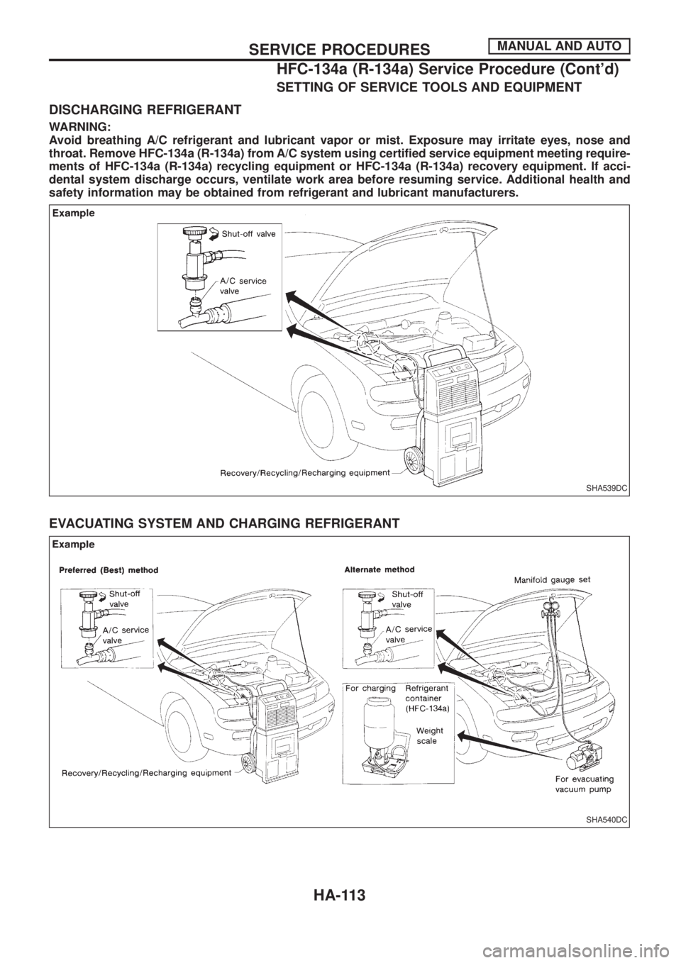
SETTING OF SERVICE TOOLS AND EQUIPMENT
DISCHARGING REFRIGERANT
WARNING:
Avoid breathing A/C refrigerant and lubricant vapor or mist. Exposure may irritate eyes, nose and
throat. Remove HFC-134a (R-134a) from A/C system using certi®ed service equipment meeting require-
ments of HFC-134a (R-134a) recycling equipment or HFC-134a (R-134a) recovery equipment. If acci-
dental system discharge occurs, ventilate work area before resuming service. Additional health and
safety information may be obtained from refrigerant and lubricant manufacturers.
EVACUATING SYSTEM AND CHARGING REFRIGERANT
SHA539DC
SHA540DC
SERVICE PROCEDURESMANUAL AND AUTO
HFC-134a (R-134a) Service Procedure (Cont'd)
HA-113
Page 954 of 1226
Tie-rod ball joints.............................................ST-19
Tie-rod .............................................................ST-19
Timing belt......................................................EM-15
Tire rotation ....................................................MA-25
Tire size ...........................................................GI-38
Tooth contact (front ®nal drive 4WD) .............PD-29
Tooth contact diff. ...........................................PD-29
Tow truck towing ..............................................GI-41
Towing point.....................................................GI-42
Transfer case ..................................................TF-10
Transfer ¯uid replacement .............................MA-21
Transfer serial number ....................................GI-37
Transmission case (M/T) ..................................MT-9
Trim .................................................................BT-14
Trouble diagnoses ...........................................GI-30
Turbocharger charge air cooler .....................EM-27
Turbocharger ..................................................EM-23
Two-pole lift .....................................................GI-40
U
Under body .....................................................BT-51
V
VSS - Wiring diagram ....................................EC-82
Vacuum hose (brake system) ........................BR-17
Vacuum hose (brake system) ........................BR-18
Vacuum hose drawing (ECCS) ......................EC-13
Valve clearance..............................................EM-40
Valve guide ....................................................EM-31
Valve lifter ......................................................EM-35
Valve seat ......................................................EM-32
Valve spring ...................................................EM-34Vehicle identi®cation number...........................GI-36
Vehicle speed sensor (VSS) ..........................EC-82
Viscosity number (SAE) .................................MA-10
W
WARN - Wiring diagram ...............................EL-123
WINDOW - Wiring diagram ..........................EL-198
WIP/R - Wiring diagram ................................EL-146
WIPER - Wiring diagram ..............................EL-142
Warning chime ..............................................EL-135
Warning lamps ..............................................EL-121
Washer, front .................................................EL-141
Washer, rear..................................................EL-145
Water pump ....................................................LC-10
Water temperature gauge .............................EL-102
Weatherstrip - See Exterior ............................BT-26
Wheel alignment (front) ....................................FA-8
Wheel bearing (front axle) ................................FA-5
Wheel bearing (rear) ........................................RA-5
Wheel hub (front) ............................................FA-14
Wheel size .......................................................GI-38
Window, back door .........................................BT-45
Window, door ....................................................BT-9
Window, rear side ...........................................BT-44
Window, side - See Rear side window ...........BT-44
Windshield.......................................................BT-42
Wiper deicer ..................................................EL-166
Wiper, front....................................................EL-141
Wiper, rear ....................................................EL-145
Wiring diagram (cell code) list ......................EL-315
Wiring diagrams.................................................GI-8
Withdrawal lever (clutch) ................................CL-11
ALPHABETICAL INDEX
IDX-7
Page 958 of 1226
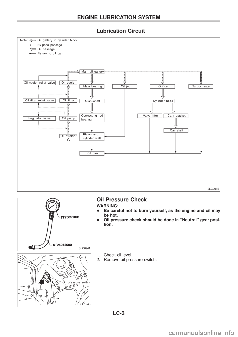
Lubrication Circuit
Oil Pressure Check
WARNING:
+Be careful not to burn yourself, as the engine and oil may
be hot.
+Oil pressure check should be done in ``Neutral'' gear posi-
tion.
1. Check oil level.
2. Remove oil pressure switch.
SLC201B
SLC694A
SLC194B
ENGINE LUBRICATION SYSTEM
LC-3
Page 964 of 1226
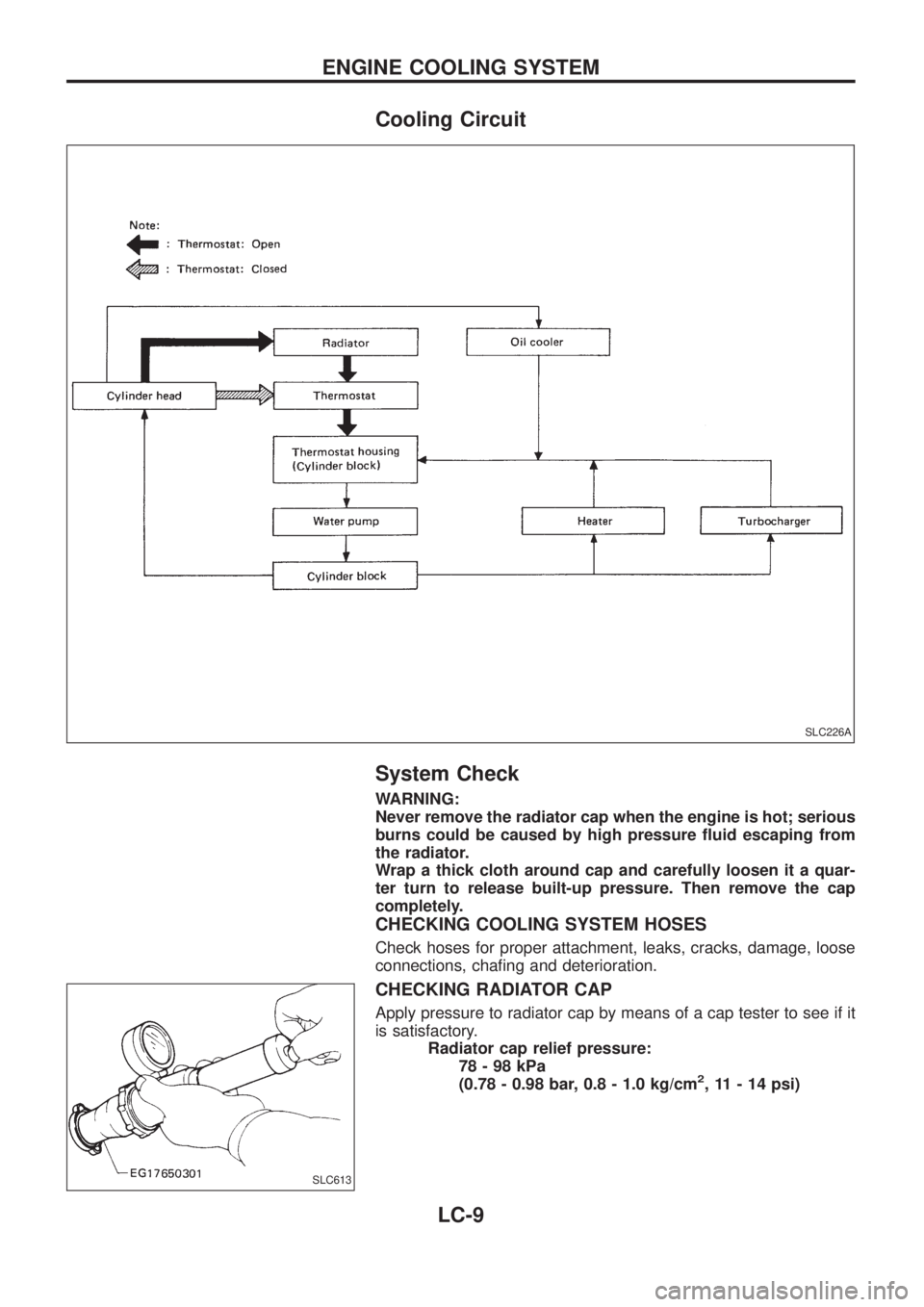
Cooling Circuit
System Check
WARNING:
Never remove the radiator cap when the engine is hot; serious
burns could be caused by high pressure ¯uid escaping from
the radiator.
Wrap a thick cloth around cap and carefully loosen it a quar-
ter turn to release built-up pressure. Then remove the cap
completely.
CHECKING COOLING SYSTEM HOSES
Check hoses for proper attachment, leaks, cracks, damage, loose
connections, cha®ng and deterioration.
CHECKING RADIATOR CAP
Apply pressure to radiator cap by means of a cap tester to see if it
is satisfactory.
Radiator cap relief pressure:
78-98kPa
(0.78 - 0.98 bar, 0.8 - 1.0 kg/cm
2, 11 - 14 psi)
SLC226A
SLC613
ENGINE COOLING SYSTEM
LC-9
Page 974 of 1226
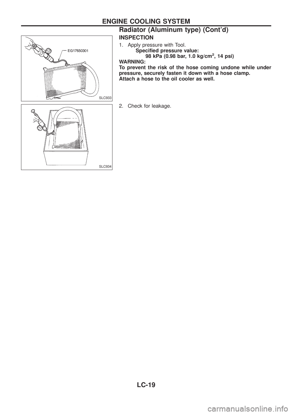
INSPECTION
1. Apply pressure with Tool.
Speci®ed pressure value:
98 kPa (0.98 bar, 1.0 kg/cm
2, 14 psi)
WARNING:
To prevent the risk of the hose coming undone while under
pressure, securely fasten it down with a hose clamp.
Attach a hose to the oil cooler as well.
2. Check for leakage.
SLC933
SLC934
ENGINE COOLING SYSTEM
Radiator (Aluminum type) (Cont'd)
LC-19
Page 978 of 1226
Supplemental Restraint System (SRS) ``AIR
BAG'' and ``SEAT BELT PRE-TENSIONER''
The Supplemental Restraint System such as ``AIR BAG'' and ``SEAT BELT PRE-TENSIONER'' used along with
a seat belt, helps to reduce the risk or severity of injury to the driver and front passenger in a frontal collision.
The SRS composition which is available to NISSAN MODEL Y61 is as follows (The composition varies
according to the destination.):
Driver air bag module (located in the center of the steering wheel), front passenger air bag module (located
on the instrument panel on passenger side), seat belt pre-tensioner, a diagnosis sensor unit, warning lamp,
wiring harness and spiral cable.
WARNING:
+To avoid rendering the SRS inoperative, which could increase the risk of personal injury or death
in the event of a collision which would result in air bag in¯ation, all maintenance must be performed
by an authorized NISSAN dealer.
+Improper maintenance, including incorrect removal and installation of the SRS, can lead to per-
sonal injury caused by unintentional activation of the system.
+Do not use electrical test equipment on any circuit related to the SRS unless instructed to in this
Service Manual. Spiral cable and wiring harnesses covered with yellow insulation either just before
the harness connectors or for the complete harness are related to the SRS.
Special Service Tools
Tool number
Tool nameDescription
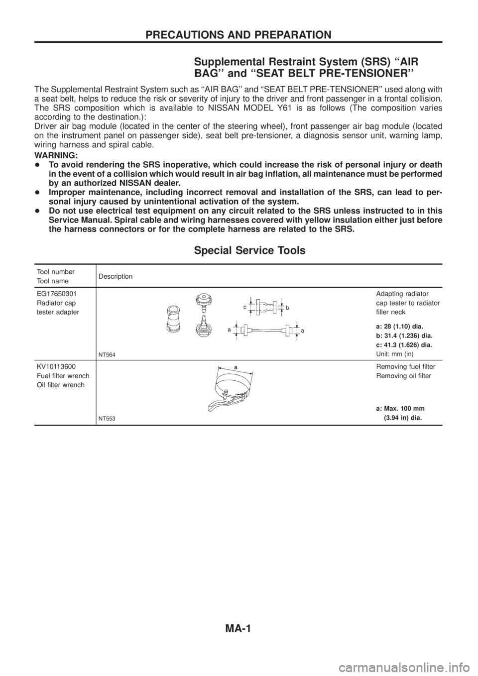
EG17650301
Radiator cap
tester adapter
NT564
Adapting radiator
cap tester to radiator
®ller neck
a: 28 (1.10) dia.
b: 31.4 (1.236) dia.
c: 41.3 (1.626) dia.
Unit: mm (in)
KV10113600
Fuel ®lter wrench
Oil ®lter wrench
NT553
Removing fuel ®lter
Removing oil ®lter
a: Max. 100 mm
(3.94 in) dia.
PRECAUTIONS AND PREPARATION
MA-1
Page 980 of 1226
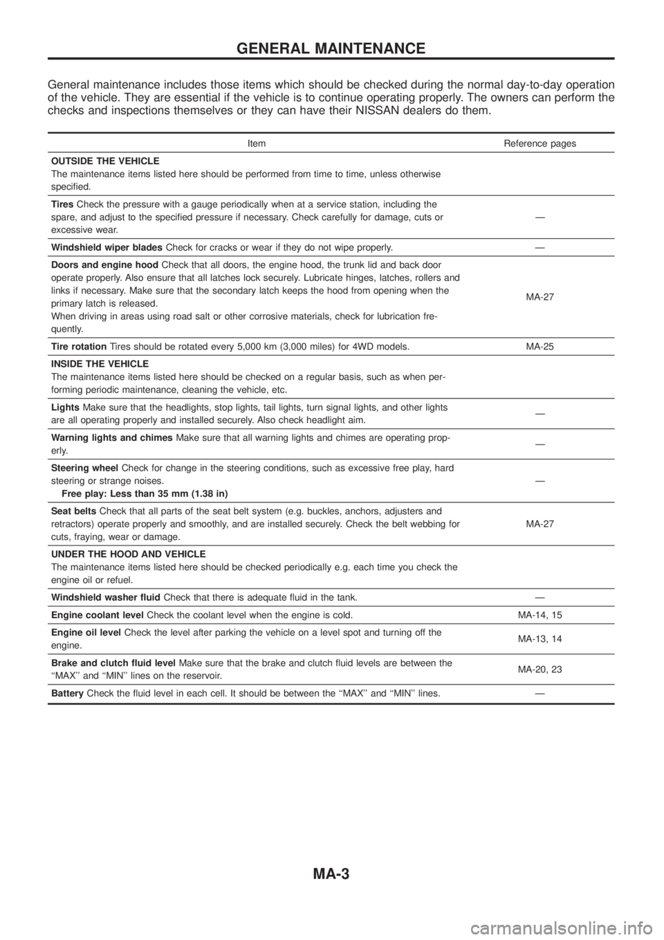
General maintenance includes those items which should be checked during the normal day-to-day operation
of the vehicle. They are essential if the vehicle is to continue operating properly. The owners can perform the
checks and inspections themselves or they can have their NISSAN dealers do them.
Item Reference pages
OUTSIDE THE VEHICLE
The maintenance items listed here should be performed from time to time, unless otherwise
speci®ed.
TiresCheck the pressure with a gauge periodically when at a service station, including the
spare, and adjust to the speci®ed pressure if necessary. Check carefully for damage, cuts or
excessive wear.Ð
Windshield wiper bladesCheck for cracks or wear if they do not wipe properly. Ð
Doors and engine hoodCheck that all doors, the engine hood, the trunk lid and back door
operate properly. Also ensure that all latches lock securely. Lubricate hinges, latches, rollers and
links if necessary. Make sure that the secondary latch keeps the hood from opening when the
primary latch is released.
When driving in areas using road salt or other corrosive materials, check for lubrication fre-
quently.MA-27
Tire rotationTires should be rotated every 5,000 km (3,000 miles) for 4WD models. MA-25
INSIDE THE VEHICLE
The maintenance items listed here should be checked on a regular basis, such as when per-
forming periodic maintenance, cleaning the vehicle, etc.
LightsMake sure that the headlights, stop lights, tail lights, turn signal lights, and other lights
are all operating properly and installed securely. Also check headlight aim.Ð
Warning lights and chimesMake sure that all warning lights and chimes are operating prop-
erly.Ð
Steering wheelCheck for change in the steering conditions, such as excessive free play, hard
steering or strange noises.
Free play: Less than 35 mm (1.38 in)Ð
Seat beltsCheck that all parts of the seat belt system (e.g. buckles, anchors, adjusters and
retractors) operate properly and smoothly, and are installed securely. Check the belt webbing for
cuts, fraying, wear or damage.MA-27
UNDER THE HOOD AND VEHICLE
The maintenance items listed here should be checked periodically e.g. each time you check the
engine oil or refuel.
Windshield washer ¯uidCheck that there is adequate ¯uid in the tank. Ð
Engine coolant levelCheck the coolant level when the engine is cold. MA-14, 15
Engine oil levelCheck the level after parking the vehicle on a level spot and turning off the
engine.MA-13, 14
Brake and clutch ¯uid levelMake sure that the brake and clutch ¯uid levels are between the
``MAX'' and ``MIN'' lines on the reservoir.MA-20, 23
BatteryCheck the ¯uid level in each cell. It should be between the ``MAX'' and ``MIN'' lines. Ð
GENERAL MAINTENANCE
MA-3
Page 990 of 1226

1. Inspect for cracks, fraying, wear or oil adhesion. Replace if
necessary.
The belts should not touch the bottom of the pulley groove.
2. Check drive belt de¯ection by pushing on the belt midway
between pulleys.
Adjust if belt de¯ections exceed the limit.
Unit: mm (in)
Used belt de¯ection
De¯ection of new belt
LimitDe¯ection after
adjustment
Alternator 17 (0.67) 12 - 14 (0.47 - 0.55) 9 - 11 (0.35 - 0.43)
Air conditioner
compressor11 (0.43)7 - 9 (0.28 - 0.35)6 - 8 (0.24 - 0.31)
Power steering oil
pump14 (0.55) 10 - 12 (0.39 - 0.47) 9 - 11 (0.35 - 0.43)
Applied pushing
force98 N (10 kg, 22 lb)
Check drive belt de¯ections when engine is cold.
Changing Engine Oil
WARNING:
+Be careful not to burn yourself, as engine oil is hot.
+Prolonged and repeated contact with used engine oil may
cause skin cancer; try to avoid direct skin contact with
used oil. If skin contact is made, wash thoroughly with
soap or hand cleaner as soon as possible.
1. Warm up engine, and check for oil leakage from engine com-
ponents.
2. Remove oil ®ller cap and drain plug.
3. Drain oil and ®ll with new engine oil.
Oil grade: CCMC PD1 or PD2
Viscosity:
See ``RECOMMENDED FLUIDS AND
LUBRICANTS'', MA-9.
Re®ll oil capacity (approximate):
Without oil ®lter change
6.4!(5-5/8 Imp qt)
With oil ®lter change
5.8!(5-1/8 Imp qt)
CAUTION:
+Be sure to clean and install oil pan drain plug with washer.
Drain plug:
:29-39Nzm (3.0 - 4.0 kg-m, 22 - 29 ft-lb)
+The re®ll capacity changes depending on the oil tempera-
ture and drain time; use these valves as a reference and be
certain to check with the dipstick when changing the oil.
SMA998C
ENGINE MAINTENANCE
Checking Drive Belt (Cont'd)
MA-13