Page 11 of 1226

1. Ensure vehicle is unladen condition*.* Fuel, radiator coolant and engine oil full. Spare tire, jack,hand tools and mats in designated positions.
2. Have a driver sit in the driver's seat and one person sit on the rear end. Then have the person on the rear end slowly get off
the vehicle. This is necessary to stabilize suspension de¯ec-
tion.
3. Gradually depress brake pedal and attach a lever to the stop- per bolt, then adjust length ``L'' as follows:Length ``L'': Approx. 175.2 - 178.2 mm (6.90 - 7.02 in)
4. Remove front LH tire.
5. Connect tool to air bleeders on front LH brake caliper and rear LH or RH brake wheel cylinder.
6. Install front LH tire.
Before installing front LH tire, con®rm the tool is not touching
the front LH wheel.
7. Bleed air from Tool.
8. Raise front brake pressure to 4,904 kPa (49.0 bar, 50 kg/cm
2,
711 psi) and 9,807 kPa (98.1 bar, 100 kg/cm2, 1,422 psi) and
check rear brake pressure. Rear brake pressure: Refer to table on next page.
SBR287E
SBR822BA
SBR823BA
SBR377D
BRAKE HYDRAULIC LINE/CONTROL VALVE
Load Sensing Valve (Cont'd)
BR-7
Page 12 of 1226

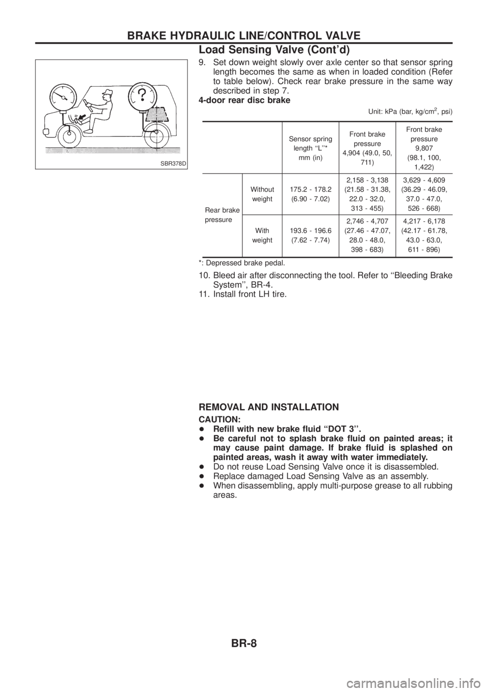
9. Set down weight slowly over axle center so that sensor springlength becomes the same as when in loaded condition (Refer
to table below). Check rear brake pressure in the same way
described in step 7.
4-door rear disc brake
Unit: kPa (bar, kg/cm2, psi)
Sensor spring
length ``L''* mm (in) Front brake
pressure
4,904 (49.0, 50, 711) Front brake
pressure 9,807
(98.1, 100, 1,422)
Rear brake
pressure Without
weight 175.2 - 178.2
(6.90 - 7.02) 2,158 - 3,138
(21.58 - 31.38, 22.0 - 32.0,313 - 455) 3,629 - 4,609
(36.29 - 46.09, 37.0 - 47.0,526 - 668)
With
weight 193.6 - 196.6
(7.62 - 7.74) 2,746 - 4,707
(27.46 - 47.07, 28.0 - 48.0,398 - 683) 4,217 - 6,178
(42.17 - 61.78, 43.0 - 63.0,611 - 896)
*: Depressed brake pedal.
10. Bleed air after disconnecting the tool. Refer to ``Bleeding Brake System'', BR-4.
11. Install front LH tire.
REMOVAL AND INSTALLATION
CAUTION:
+ Re®ll with new brake ¯uid ``DOT 3''.
+ Be careful not to splash brake ¯uid on painted areas; it
may cause paint damage. If brake ¯uid is splashed on
painted areas, wash it away with water immediately.
+ Do not reuse Load Sensing Valve once it is disassembled.
+ Replace damaged Load Sensing Valve as an assembly.
+ When disassembling, apply multi-purpose grease to all rubbing
areas.
SBR378D
BRAKE HYDRAULIC LINE/CONTROL VALVE
Load Sensing Valve (Cont'd)
BR-8
Page 19 of 1226

Brake Booster
ON-VEHICLE SERVICE
Operating check
+Depress brake pedal several times with engine off. After
exhausting vacuum, make sure there is no change in pedal
stroke.
+ Depress brake pedal, then start engine. If pedal goes down
slightly, operation is normal.
Airtight check
+Start engine, and stop it after one or two minutes. Depress
brake pedal several times slowly. Booster is airtight if pedal
stroke is less each time.
+ Depress brake pedal while engine is running, and stop engine
with pedal depressed. The pedal stroke should not change after
holding pedal down for 30 seconds.
REMOVAL
CAUTION:
+Be careful not to splash brake ¯uid on painted areas; it
may cause paint damage. If brake ¯uid is splashed on
painted areas, wash it away with water immediately.
+ Be careful not to deform or bend brake pipes, during
removal of booster.
INSPECTION
Output rod length check
1. Apply vacuum of þ66.7 kPa (þ500 mmHg, þ19.69 inHg) to
brake booster with a hand vacuum pump.
2. Check output rod length. Speci®ed length:10.275 - 10.525 mm (0.4045 - 0.4144 in)
INSTALLATION
CAUTION:
+Be careful not to deform or bend brake pipes during instal-
lation of booster.
+ Replace clevis pin if damaged.
+ Re®ll with new brake ¯uid ``DOT 3''.
+ Never reuse drained brake ¯uid.
+ Take care not to damage brake booster mounting bolt
thread when installing. Due to the narrow angle of
installation, the threads can be damaged by the dash
panel.
SBR002A
SBR365AA
SBR170E
SBR281A
SBR116BF
BRAKE BOOSTER
BR-15
Page 76 of 1226

General Speci®cations
Applied modelExcept for Europe, Australia and Middle East
Europe, Australia and
Middle East
Standard Option All
Front brake Type CL36VE disc brake
Cylinder bore diameter mm (in) 48.1 (1.894) x 2
Pad dimension mm (in)
Length x width x thickness 147 x 56.5 x 12 (5.79 x 2.224 x 0.47)
Rotor outer diameter x thickness mm (in) 306 x 32 (12.05 x 1.26)
Rear brake Type LT30 drum brake CL18VF disc brake
Cylinder bore diameter mm (in) 25.4 (1.00) 48.1 (1.894)
Lining or pad dimension mm (in)
Length x width x thickness 296x50x6.1
(11.65 x 1.97 x 0.240) 111x41.8x10
(4.37 x 1.646 x 0.39)
Drum inner diameter mm (in) 295 (11.61) Ð
Rotor outer diameter x thickness mm (in)Ð 316 x 18 (12.44 x 0.71)
Applied model Except for 4-door rear disc
brake 4-door rear disc brake
Brake booster Model 235T
Diaphragm diameter mm (in) Primary: 252
Secondary: 230
Master cylinder bore diameter mm (in) 25.4 (1.00)
Control valve Type LSV
Split point x reducing ratio kPa (bar, kg/cm
2, psi)(Variable) x 0.15 (Variable) x 0.3
Recommended brake ¯uid DOT 3
SERVICE DATA AND SPECIFICATIONS (SDS)
BR-72
Page 117 of 1226
ADJUSTMENT
Install motor & limit SW assembly and sunroof rail assembly in the following sequence:
1. Arrange equal lengths of link and wire assemblies on both sides of sunroof opening.
2. Connect sunroof connector to sunroof switch and positive (+) power supply.
3. Set lid assembly to fully closed position
by operating OPEN switch and TILT switch.
4. Fit outer side of lid assembly to the surface of roof on body outer panel.
5. Remove motor, and keep OPEN switch pressed until motor pinion gear reaches the end of its rotating
range.
6. Install motor.
7. Check that motor drive gear ®ts properly in wires.
8. Press TILT-UP switch to check lid assembly for normal tilting.
9. Check sunroof lid assembly for normal operations (tilt-up, tilt-down, open, and close).
SBF920F
SUNROOF
BT-39
Page 127 of 1226
+All dimensions indicated in ®gures are actual ones.
+When using a tracking gauge, adjust both pointers to equal length. Then check the pointers and gauge
itself to make sure there is no free play.
+When a measuring tape is used, check to be sure there is no elongation, twisting or bending.
+Measurements should be taken at the center of the mounting holes.
+An asterisk (*) following the value at the measuring point indicates that the measuring point on the other
side is symmetrically the same value.
+The coordinates of the measurement points are the distances measured from the standard line of ``X'', ``Y''
and ``Z''.
Engine Compartment
MEASUREMENT
SBF874GD
SBT560
BODY ALIGNMENT
BT-49
Page 143 of 1226
ADJUSTMENT
Output rod length:
Length ``A''
1.30 - 1.55 mm (0.0512 - 0.0610 in)
If amount of adjustment required exceeds 0.5 mm (0.020 in),
reaction disc may have either been dislocated or fallen off.
Replace clutch booster assembly.
Input rod length:
Length ``B''
130 mm (5.12 in)
SCL135
SCL140
SCL136
HYDRAULIC CLUTCH CONTROL
Clutch Booster (Cont'd)
CL-10
Page 149 of 1226

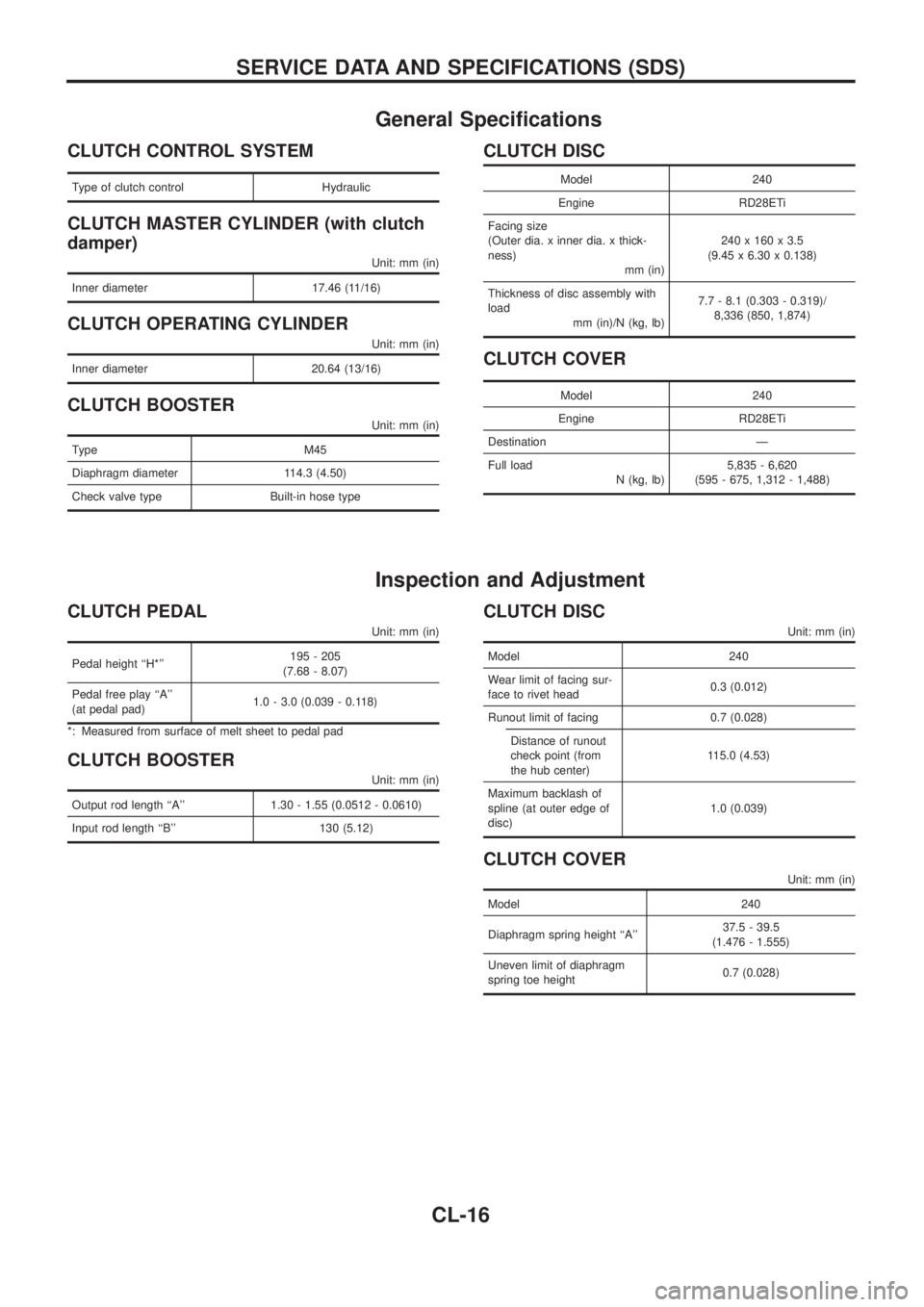
General Speci®cations
CLUTCH CONTROL SYSTEM
Type of clutch control Hydraulic
CLUTCH MASTER CYLINDER (with clutch
damper)
Unit: mm (in)
Inner diameter 17.46 (11/16)
CLUTCH OPERATING CYLINDER
Unit: mm (in)
Inner diameter 20.64 (13/16)
CLUTCH BOOSTER
Unit: mm (in)
Type M45
Diaphragm diameter 114.3 (4.50)
Check valve type Built-in hose type
CLUTCH DISC
Model 240
Engine RD28ETi
Facing size
(Outer dia. x inner dia. x thick-
ness)
mm (in)240 x 160 x 3.5
(9.45 x 6.30 x 0.138)
Thickness of disc assembly with
load
mm (in)/N (kg, lb)7.7 - 8.1 (0.303 - 0.319)/
8,336 (850, 1,874)
CLUTCH COVER
Model 240
Engine RD28ETi
Destination Ð
Full load
N (kg, lb)5,835 - 6,620
(595 - 675, 1,312 - 1,488)
Inspection and Adjustment
CLUTCH PEDAL
Unit: mm (in)
Pedal height ``H*''195 - 205
(7.68 - 8.07)
Pedal free play ``A''
(at pedal pad)1.0 - 3.0 (0.039 - 0.118)
*: Measured from surface of melt sheet to pedal pad
CLUTCH BOOSTER
Unit: mm (in)
Output rod length ``A'' 1.30 - 1.55 (0.0512 - 0.0610)
Input rod length ``B'' 130 (5.12)
CLUTCH DISC
Unit: mm (in)
Model 240
Wear limit of facing sur-
face to rivet head0.3 (0.012)
Runout limit of facing 0.7 (0.028)
Distance of runout
check point (from
the hub center)115.0 (4.53)
Maximum backlash of
spline (at outer edge of
disc)1.0 (0.039)
CLUTCH COVER
Unit: mm (in)
Model 240
Diaphragm spring height ``A''37.5 - 39.5
(1.476 - 1.555)
Uneven limit of diaphragm
spring toe height0.7 (0.028)
SERVICE DATA AND SPECIFICATIONS (SDS)
CL-16