2006 NISSAN PATROL length
[x] Cancel search: lengthPage 726 of 1226
VA LV E
Unit: mm (in)
SEM188A
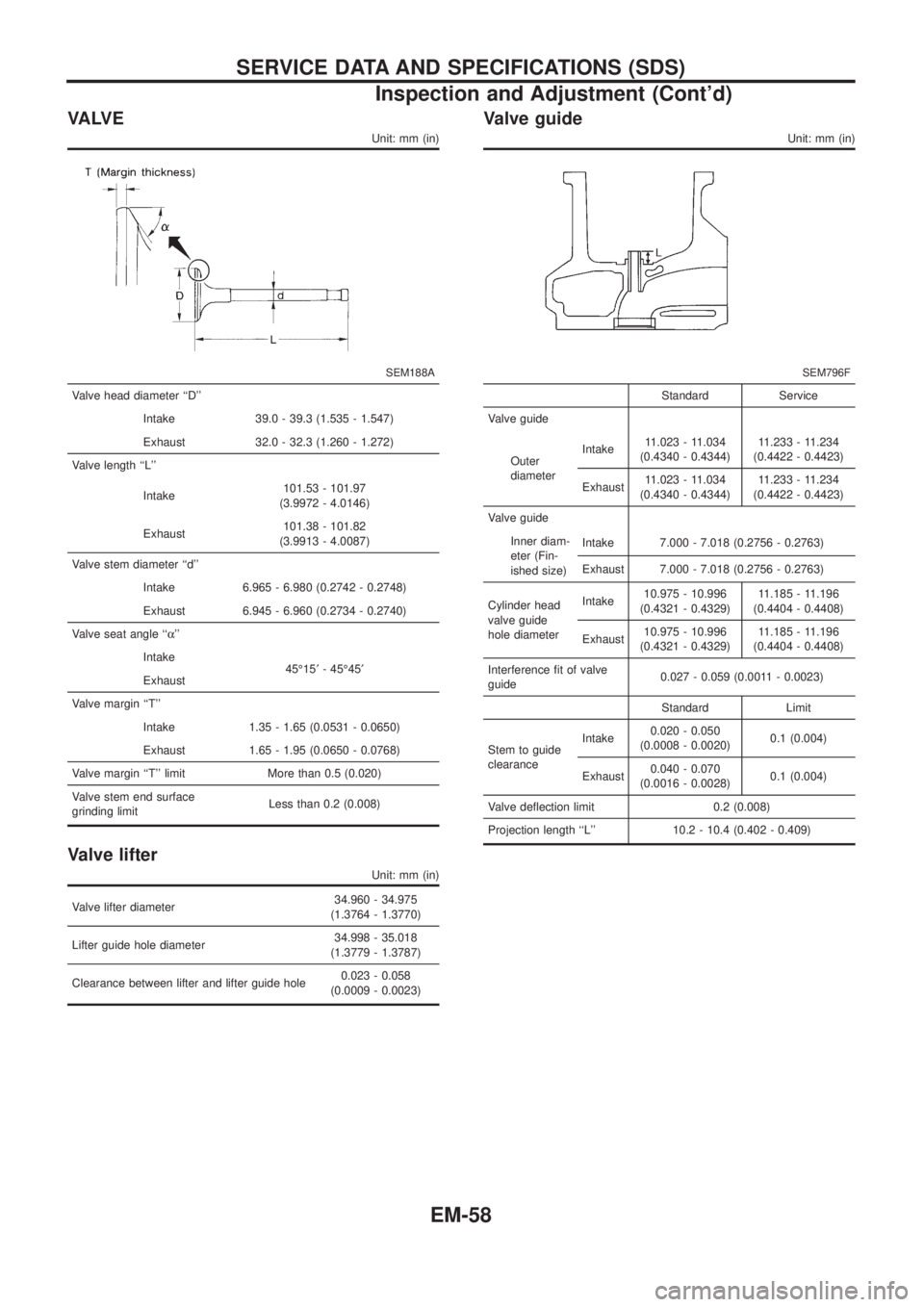
Valve head diameter ``D''
Intake 39.0 - 39.3 (1.535 - 1.547)
Exhaust 32.0 - 32.3 (1.260 - 1.272)
Valve length ``L''
Intake101.53 - 101.97
(3.9972 - 4.0146)
Exhaust101.38 - 101.82
(3.9913 - 4.0087)
Valve stem diameter ``d''
Intake 6.965 - 6.980 (0.2742 - 0.2748)
Exhaust 6.945 - 6.960 (0.2734 - 0.2740)
Valve seat angle ``a''
Intake
45É15¢- 45É45¢
Exhaust
Valve margin ``T''
Intake 1.35 - 1.65 (0.0531 - 0.0650)
Exhaust 1.65 - 1.95 (0.0650 - 0.0768)
Valve margin ``T'' limit More than 0.5 (0.020)
Valve stem end surface
grinding limitLess than 0.2 (0.008)
Valve lifter
Unit: mm (in)
Valve lifter diameter34.960 - 34.975
(1.3764 - 1.3770)
Lifter guide hole diameter34.998 - 35.018
(1.3779 - 1.3787)
Clearance between lifter and lifter guide hole0.023 - 0.058
(0.0009 - 0.0023)
Valve guide
Unit: mm (in)
SEM796F
Standard Service
Valve guide
Outer
diameterIntake11.023 - 11.034
(0.4340 - 0.4344)11.233 - 11.234
(0.4422 - 0.4423)
Exhaust11.023 - 11.034
(0.4340 - 0.4344)11.233 - 11.234
(0.4422 - 0.4423)
Valve guide
Inner diam-
eter (Fin-
ished size)Intake 7.000 - 7.018 (0.2756 - 0.2763)
Exhaust 7.000 - 7.018 (0.2756 - 0.2763)
Cylinder head
valve guide
hole diameterIntake10.975 - 10.996
(0.4321 - 0.4329)11.185 - 11.196
(0.4404 - 0.4408)
Exhaust10.975 - 10.996
(0.4321 - 0.4329)11.185 - 11.196
(0.4404 - 0.4408)
Interference ®t of valve
guide0.027 - 0.059 (0.0011 - 0.0023)
Standard Limit
Stem to guide
clearanceIntake0.020 - 0.050
(0.0008 - 0.0020)0.1 (0.004)
Exhaust0.040 - 0.070
(0.0016 - 0.0028)0.1 (0.004)
Valve de¯ection limit 0.2 (0.008)
Projection length ``L'' 10.2 - 10.4 (0.402 - 0.409)
SERVICE DATA AND SPECIFICATIONS (SDS)
Inspection and Adjustment (Cont'd)
EM-58
Page 742 of 1226
TOE-IN
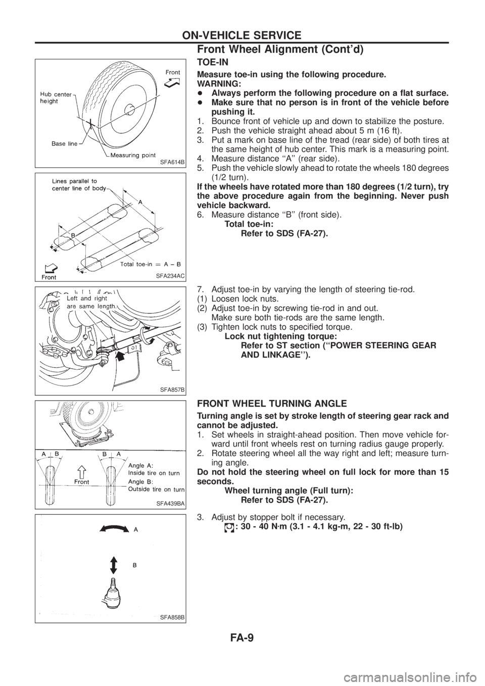
Measure toe-in using the following procedure.
WARNING:
+Always perform the following procedure on a ¯at surface.
+Make sure that no person is in front of the vehicle before
pushing it.
1. Bounce front of vehicle up and down to stabilize the posture.
2. Push the vehicle straight ahead about 5 m (16 ft).
3. Put a mark on base line of the tread (rear side) of both tires at
the same height of hub center. This mark is a measuring point.
4. Measure distance ``A'' (rear side).
5. Push the vehicle slowly ahead to rotate the wheels 180 degrees
(1/2 turn).
If the wheels have rotated more than 180 degrees (1/2 turn), try
the above procedure again from the beginning. Never push
vehicle backward.
6. Measure distance ``B'' (front side).
Total toe-in:
Refer to SDS (FA-27).
7. Adjust toe-in by varying the length of steering tie-rod.
(1) Loosen lock nuts.
(2) Adjust toe-in by screwing tie-rod in and out.
Make sure both tie-rods are the same length.
(3) Tighten lock nuts to speci®ed torque.
Lock nut tightening torque:
Refer to ST section (``POWER STEERING GEAR
AND LINKAGE'').
FRONT WHEEL TURNING ANGLE
Turning angle is set by stroke length of steering gear rack and
cannot be adjusted.
1. Set wheels in straight-ahead position. Then move vehicle for-
ward until front wheels rest on turning radius gauge properly.
2. Rotate steering wheel all the way right and left; measure turn-
ing angle.
Do not hold the steering wheel on full lock for more than 15
seconds.
Wheel turning angle (Full turn):
Refer to SDS (FA-27).
3. Adjust by stopper bolt if necessary.
:30-40Nzm (3.1 - 4.1 kg-m, 22 - 30 ft-lb)
SFA614B
SFA234AC
SFA857B
SFA439BA
SFA858B
ON-VEHICLE SERVICE
Front Wheel Alignment (Cont'd)
FA-9
Page 811 of 1226
Dimensions
Wagon Hardtop
Overall length mm (in) 4,965 (195.5)
5,010 (197.2)*4,395 (173.0)
4,440 (174.8)*
Overall width mm (in) 1,840 (72.4)
1,930 (76.0)*1,840 (72.4)
1,930 (76.0)*
Overall height mm (in) 1,855 (73.0) 1,840 (72.4)
Front tread mm (in) 1,555 (61.2)
1,605 (63.2)*1,555 (61.2)
1,605 (63.2)*
Rear tread mm (in) 1,575 (62.0)
1,625 (64.0)*1,575 (62.0)
1,625 (64.0)*
Wheelbase mm (in) 2,970 (116.9) 2,400 (94.5)
*: For models equipped with 265/70R16 tires
Wheels & Tires
Road wheel
Size 6JJ-16*1 8JJ-16*1
Offset mm (in) 35 (1.38) 10 (0.39)
Tire size 235/80R16 109S 265/70R16 112S
*1: Steel wheel and Aluminum wheel
IDENTIFICATION INFORMATION
GI-38
Page 1065 of 1226
Adjustment
FRICTION DISC AND FRICTION PLATE END PLAY
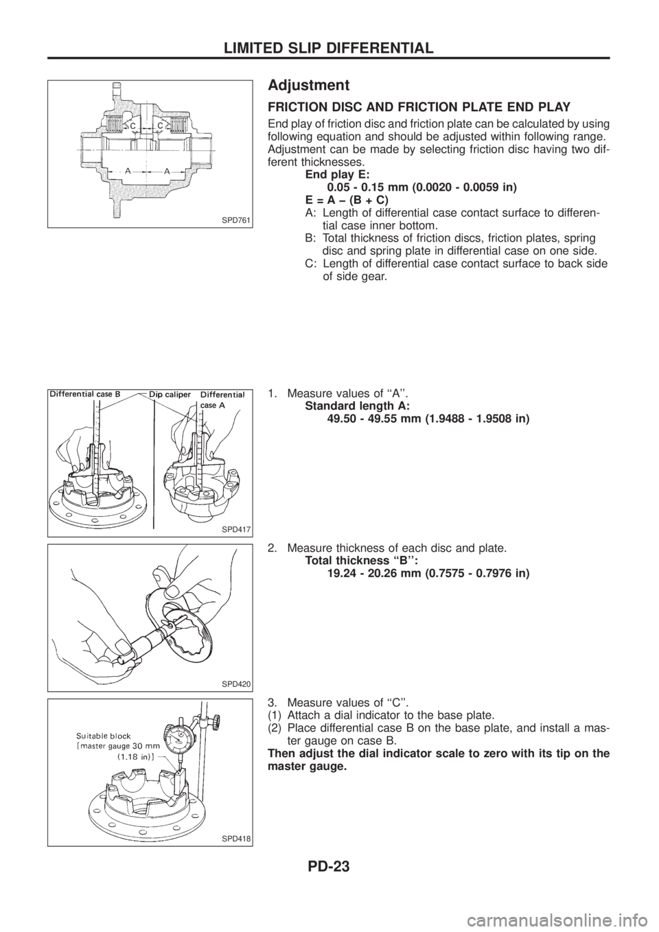
End play of friction disc and friction plate can be calculated by using
following equation and should be adjusted within following range.
Adjustment can be made by selecting friction disc having two dif-
ferent thicknesses.
End play E:
0.05 - 0.15 mm (0.0020 - 0.0059 in)
E=Aþ(B+C)
A: Length of differential case contact surface to differen-
tial case inner bottom.
B: Total thickness of friction discs, friction plates, spring
disc and spring plate in differential case on one side.
C: Length of differential case contact surface to back side
of side gear.
1. Measure values of ``A''.
Standard length A:
49.50 - 49.55 mm (1.9488 - 1.9508 in)
2. Measure thickness of each disc and plate.
Total thickness ``B'':
19.24 - 20.26 mm (0.7575 - 0.7976 in)
3. Measure values of ``C''.
(1) Attach a dial indicator to the base plate.
(2) Place differential case B on the base plate, and install a mas-
ter gauge on case B.
Then adjust the dial indicator scale to zero with its tip on the
master gauge.
SPD761
SPD417
SPD420
SPD418
LIMITED SLIP DIFFERENTIAL
PD-23
Page 1083 of 1226
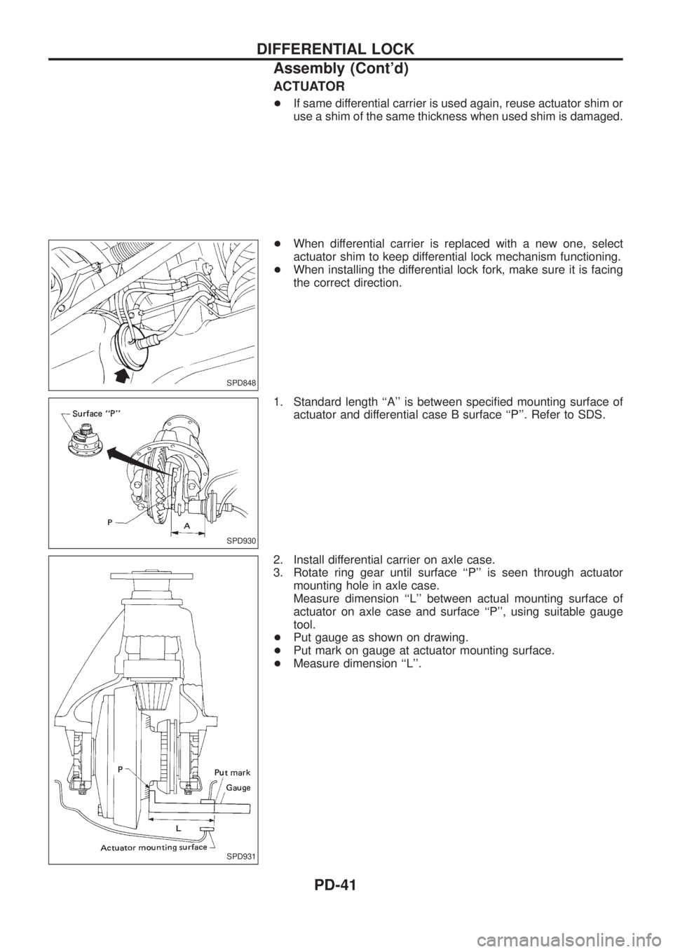
ACTUATOR
+If same differential carrier is used again, reuse actuator shim or
use a shim of the same thickness when used shim is damaged.
+When differential carrier is replaced with a new one, select
actuator shim to keep differential lock mechanism functioning.
+When installing the differential lock fork, make sure it is facing
the correct direction.
1. Standard length ``A'' is between speci®ed mounting surface of
actuator and differential case B surface ``P''. Refer to SDS.
2. Install differential carrier on axle case.
3. Rotate ring gear until surface ``P'' is seen through actuator
mounting hole in axle case.
Measure dimension ``L'' between actual mounting surface of
actuator on axle case and surface ``P'', using suitable gauge
tool.
+Put gauge as shown on drawing.
+Put mark on gauge at actuator mounting surface.
+Measure dimension ``L''.
SPD848
SPD930
SPD931
DIFFERENTIAL LOCK
Assembly (Cont'd)
PD-41
Page 1093 of 1226
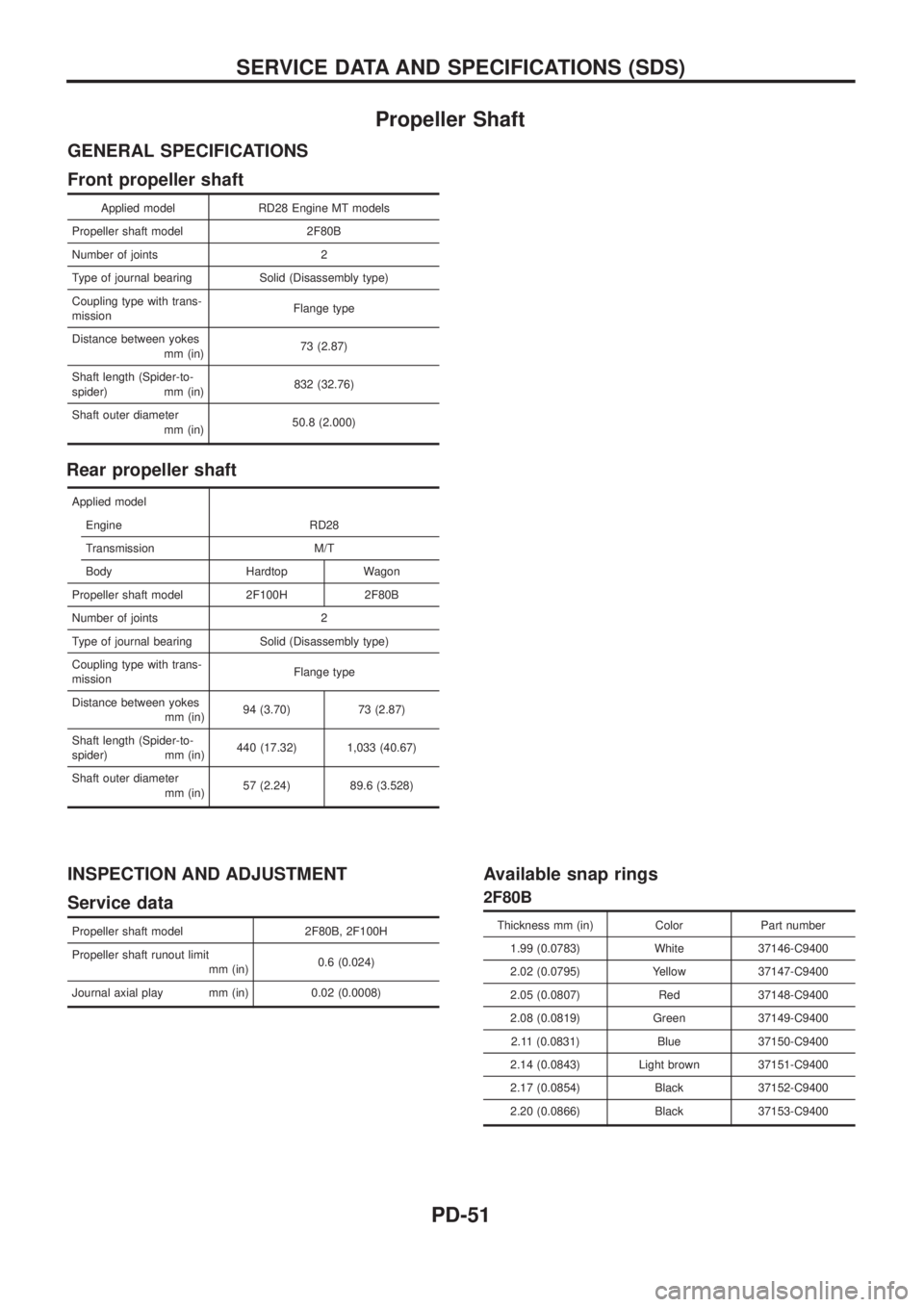
Propeller Shaft
GENERAL SPECIFICATIONS
Front propeller shaft
Applied model RD28 Engine MT models
Propeller shaft model 2F80B
Number of joints 2
Type of journal bearing Solid (Disassembly type)
Coupling type with trans-
missionFlange type
Distance between yokes
mm (in)73 (2.87)
Shaft length (Spider-to-
spider) mm (in)832 (32.76)
Shaft outer diameter
mm (in)50.8 (2.000)
Rear propeller shaft
Applied model
Engine RD28
Transmission M/T
Body Hardtop Wagon
Propeller shaft model 2F100H 2F80B
Number of joints 2
Type of journal bearing Solid (Disassembly type)
Coupling type with trans-
missionFlange type
Distance between yokes
mm (in)94 (3.70) 73 (2.87)
Shaft length (Spider-to-
spider) mm (in)440 (17.32) 1,033 (40.67)
Shaft outer diameter
mm (in)57 (2.24) 89.6 (3.528)
INSPECTION AND ADJUSTMENT
Service data
Propeller shaft model 2F80B, 2F100H
Propeller shaft runout limit
mm (in)0.6 (0.024)
Journal axial play mm (in) 0.02 (0.0008)
Available snap rings
2F80B
Thickness mm (in) Color Part number
1.99 (0.0783) White 37146-C9400
2.02 (0.0795) Yellow 37147-C9400
2.05 (0.0807) Red 37148-C9400
2.08 (0.0819) Green 37149-C9400
2.11 (0.0831) Blue 37150-C9400
2.14 (0.0843) Light brown 37151-C9400
2.17 (0.0854) Black 37152-C9400
2.20 (0.0866) Black 37153-C9400
SERVICE DATA AND SPECIFICATIONS (SDS)
PD-51
Page 1095 of 1226
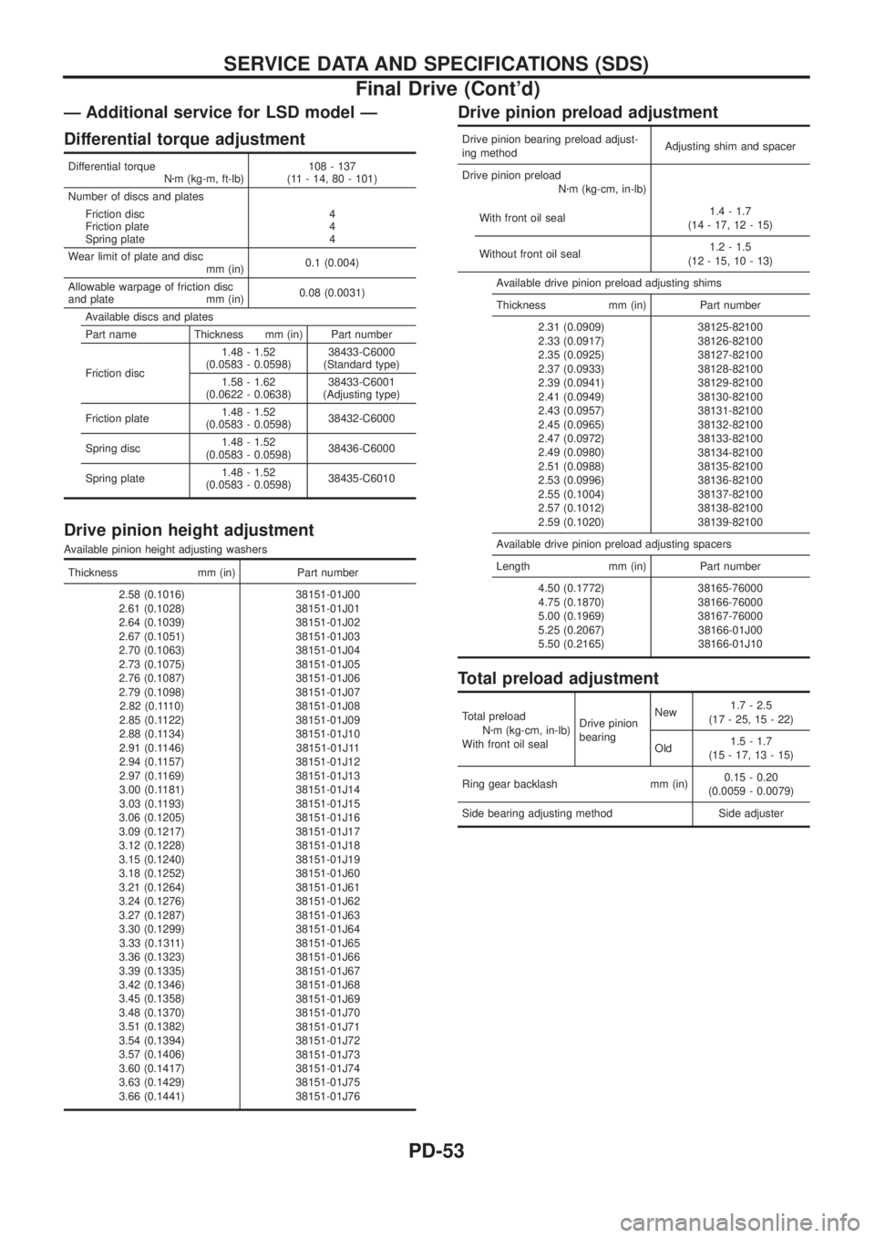
Ð Additional service for LSD model Ð
Differential torque adjustment
Differential torque
Nzm (kg-m, ft-lb)108 - 137
(11 - 14, 80 - 101)
Number of discs and plates
Friction disc
Friction plate
Spring plate4
4
4
Wear limit of plate and disc
mm (in)0.1 (0.004)
Allowable warpage of friction disc
and plate mm (in)0.08 (0.0031)
Available discs and plates
Part name Thickness mm (in) Part number
Friction disc1.48 - 1.52
(0.0583 - 0.0598)38433-C6000
(Standard type)
1.58 - 1.62
(0.0622 - 0.0638)38433-C6001
(Adjusting type)
Friction plate1.48 - 1.52
(0.0583 - 0.0598)38432-C6000
Spring disc1.48 - 1.52
(0.0583 - 0.0598)38436-C6000
Spring plate1.48 - 1.52
(0.0583 - 0.0598)38435-C6010
Drive pinion height adjustment
Available pinion height adjusting washers
Thickness mm (in) Part number
2.58 (0.1016)
2.61 (0.1028)
2.64 (0.1039)
2.67 (0.1051)
2.70 (0.1063)
2.73 (0.1075)
2.76 (0.1087)
2.79 (0.1098)
2.82 (0.1110)
2.85 (0.1122)
2.88 (0.1134)
2.91 (0.1146)
2.94 (0.1157)
2.97 (0.1169)
3.00 (0.1181)
3.03 (0.1193)
3.06 (0.1205)
3.09 (0.1217)
3.12 (0.1228)
3.15 (0.1240)
3.18 (0.1252)
3.21 (0.1264)
3.24 (0.1276)
3.27 (0.1287)
3.30 (0.1299)
3.33 (0.1311)
3.36 (0.1323)
3.39 (0.1335)
3.42 (0.1346)
3.45 (0.1358)
3.48 (0.1370)
3.51 (0.1382)
3.54 (0.1394)
3.57 (0.1406)
3.60 (0.1417)
3.63 (0.1429)
3.66 (0.1441)38151-01J00
38151-01J01
38151-01J02
38151-01J03
38151-01J04
38151-01J05
38151-01J06
38151-01J07
38151-01J08
38151-01J09
38151-01J10
38151-01J11
38151-01J12
38151-01J13
38151-01J14
38151-01J15
38151-01J16
38151-01J17
38151-01J18
38151-01J19
38151-01J60
38151-01J61
38151-01J62
38151-01J63
38151-01J64
38151-01J65
38151-01J66
38151-01J67
38151-01J68
38151-01J69
38151-01J70
38151-01J71
38151-01J72
38151-01J73
38151-01J74
38151-01J75
38151-01J76
Drive pinion preload adjustment
Drive pinion bearing preload adjust-
ing methodAdjusting shim and spacer
Drive pinion preload
Nzm (kg-cm, in-lb)
With front oil seal1.4 - 1.7
(14 - 17, 12 - 15)
Without front oil seal1.2 - 1.5
(12 - 15, 10 - 13)
Available drive pinion preload adjusting shims
Thickness mm (in) Part number
2.31 (0.0909)
2.33 (0.0917)
2.35 (0.0925)
2.37 (0.0933)
2.39 (0.0941)
2.41 (0.0949)
2.43 (0.0957)
2.45 (0.0965)
2.47 (0.0972)
2.49 (0.0980)
2.51 (0.0988)
2.53 (0.0996)
2.55 (0.1004)
2.57 (0.1012)
2.59 (0.1020)38125-82100
38126-82100
38127-82100
38128-82100
38129-82100
38130-82100
38131-82100
38132-82100
38133-82100
38134-82100
38135-82100
38136-82100
38137-82100
38138-82100
38139-82100
Available drive pinion preload adjusting spacers
Length mm (in) Part number
4.50 (0.1772)
4.75 (0.1870)
5.00 (0.1969)
5.25 (0.2067)
5.50 (0.2165)38165-76000
38166-76000
38167-76000
38166-01J00
38166-01J10
Total preload adjustment
Total preload
Nzm (kg-cm, in-lb)
With front oil sealDrive pinion
bearingNew1.7 - 2.5
(17 - 25, 15 - 22)
Old1.5 - 1.7
(15 - 17, 13 - 15)
Ring gear backlash mm (in)0.15 - 0.20
(0.0059 - 0.0079)
Side bearing adjusting method Side adjuster
SERVICE DATA AND SPECIFICATIONS (SDS)
Final Drive (Cont'd)
PD-53
Page 1180 of 1226
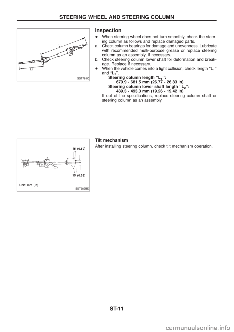
Inspection
+When steering wheel does not turn smoothly, check the steer-
ing column as follows and replace damaged parts.
a. Check column bearings for damage and unevenness. Lubricate
with recommended multi-purpose grease or replace steering
column as an assembly, if necessary.
b. Check steering column lower shaft for deformation and break-
age. Replace if necessary.
+When the vehicle comes into a light collision, check length ``L
1''
and ``L
2''.
Steering column length ``L
1'':
679.9 - 681.5 mm (26.77 - 26.83 in)
Steering column lower shaft length ``L
2'':
489.3 - 493.3 mm (19.26 - 19.42 in)
If out of the speci®cations, replace steering column shaft or
steering column as an assembly.
Tilt mechanism
After installing steering column, check tilt mechanism operation.
SST761C
SST582BD
STEERING WHEEL AND STEERING COLUMN
ST-11