Page 393 of 1226

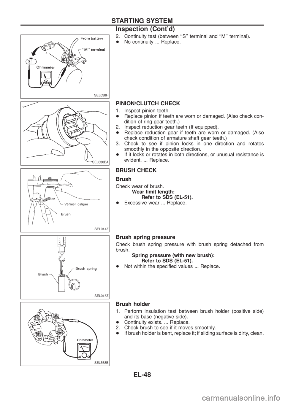
2. Continuity test (between ``S'' terminal and ``M'' terminal).
+No continuity ... Replace.
PINION/CLUTCH CHECK
1. Inspect pinion teeth.
+Replace pinion if teeth are worn or damaged. (Also check con-
dition of ring gear teeth.)
2. Inspect reduction gear teeth (If equipped).
+Replace reduction gear if teeth are worn or damaged. (Also
check condition of armature shaft gear teeth.)
3. Check to see if pinion locks in one direction and rotates
smoothly in the opposite direction.
+If it locks or rotates in both directions, or unusual resistance is
evident. ... Replace.
BRUSH CHECK
Brush
Check wear of brush.
Wear limit length:
Refer to SDS (EL-51).
+Excessive wear ... Replace.
Brush spring pressure
Check brush spring pressure with brush spring detached from
brush.
Spring pressure (with new brush):
Refer to SDS (EL-51).
+Not within the speci®ed values ... Replace.
Brush holder
1. Perform insulation test between brush holder (positive side)
and its base (negative side).
+Continuity exists. ... Replace.
2. Check brush to see if it moves smoothly.
+If brush holder is bent, replace it; if sliding surface is dirty, clean.
SEL038H
SEL630BA
SEL014Z
SEL015Z
SEL568B
STARTING SYSTEM
Inspection (Cont'd)
EL-48
Page 395 of 1226
5. Check depth of insulating mold from commutator surface.
+Less than 0.2 mm (0.008 in) ... Undercut to 0.5 to 0.8 mm
(0.020 to 0.031 in)
Assembly
Apply high-temperature grease to lubricate the bearing, gears and
frictional surface when assembling the starter.
Carefully observe the following instructions.
PINION PROTRUSION LENGTH ADJUSTMENT
Clearance ``!''
With pinion driven out by magnetic switch, push pinion back to
remove slack and measure clearance ``!'' between the front edge
of the pinion and the pinion stopper.
Clearance ``!'':
Refer to SDS (EL-51).
Movement ``!''
Compare movement ``!'' in height of pinion when it is pushed out
with magnetic switch energized and when it is pulled out by hand
until it touches stopper.
Movement ``!'':
Refer to SDS (EL-51).
SEL022Z
SEL026Z
SEL497D
STARTING SYSTEM
Inspection (Cont'd)
EL-50
Page 396 of 1226
+Not in the speci®ed value ... Adjust by adjusting plate.
Service Data and Speci®cations (SDS)
STARTER
TypeS13-502
HITACHI make
Reduction gear type
Applied model RD28
System voltage V 12
No-load
Terminal voltage V 11
Current A Less than 125
Revolution rpm 4,000
Minimum diameter of commutator
mm (in)35.5 (1.398)
Minimum length of brush mm (in) 11 (0.43)
Brush spring tension
N (kg, lb)28.4 - 34.3
(2.9 - 3.5,
6.4 - 7.7)
Clearance between bearing metal
and armature shaft mm (in)Ð
Clearance ``!'' between pinion
front edge and pinion stopper
mm (in)Ð
Movement ``!'' in height of pinion
assembly mm (in)0.3 - 2.0
(0.012 - 0.079)
SEL633BA
STARTING SYSTEM
Assembly (Cont'd)
EL-51
Page 401 of 1226
Assembly
RING FITTING IN REAR BEARING
+Fix ring into groove in rear bearing so that it is as close to the
adjacent area as possible.
CAUTION:
Do not reuse rear bearing after removal.
REAR COVER INSTALLATION
1. Fit brush assembly, diode assembly, regulator assembly and
stator.
2. Push brushes up with ®ngers and install them to rotor.
Take care not to damage slip ring sliding surface.
Service Data and Speci®cations (SDS)
ALTERNATOR
TypeA3TA4399
MITSUBISHI
Applied model RD28
Nominal rating V-A 12-100
Ground polarity Negative
Minimum revolution under no-load
(When 13.5V is applied) rpmLess than 1,300
Hot output current
(When 13.5V is applied)
A/rpmMore than 35/1,300
More than 72/2,500
Regulated output voltage V 14.1 - 14.7
Minimum length of brush mm (in) 5 (0.20)
Brush spring pressure
N (g, oz)4.6 - 5.8
(470 - 590, 16.58 - 20.81)
Slip ring minimum outer diameter
mm (in)22.1 (0.870)
Rotor (Field coil) resistanceW2.1 - 2.5
SEL044Z
SEL048Z
SEL049Z
CHARGING SYSTEM
EL-56
Page 683 of 1226
3. Remove engine gussets and oil pan bolts.
+Remove bolts/nuts in numerical order shown in ®gure, alternat-
ing left and right ones toward the center.
4. Remove oil pump assembly.
Installation
Always install with new oil seal.
1. Install oil pump assembly.
Location Bolt length mm (in)
V120 (0.79)
V235 (1.38)
V345 (1.77)
V455 (2.17)
2. Install oil pan. Tighten bolts in the order shown in the ®gure.
+Always replace oil pan gaskets with new ones when reas-
sembling.
+Install oil pan gasket after cleaning the contacting surface.
+Oil pan bolts/nuts:
Bolt
:8-12Nzm (0.8 - 1.2 kg-m, 69 - 104 in-lb)
Nut
:10-14Nzm (1.0 - 1.4 kg-m, 87 - 122 in-lb)
3. Install engine gusset and oil pan guard.
SEM739B
SEM432C
SEM794F
SEM739BA
OIL PAN
Removal (Cont'd)
EM-15
Page 703 of 1226

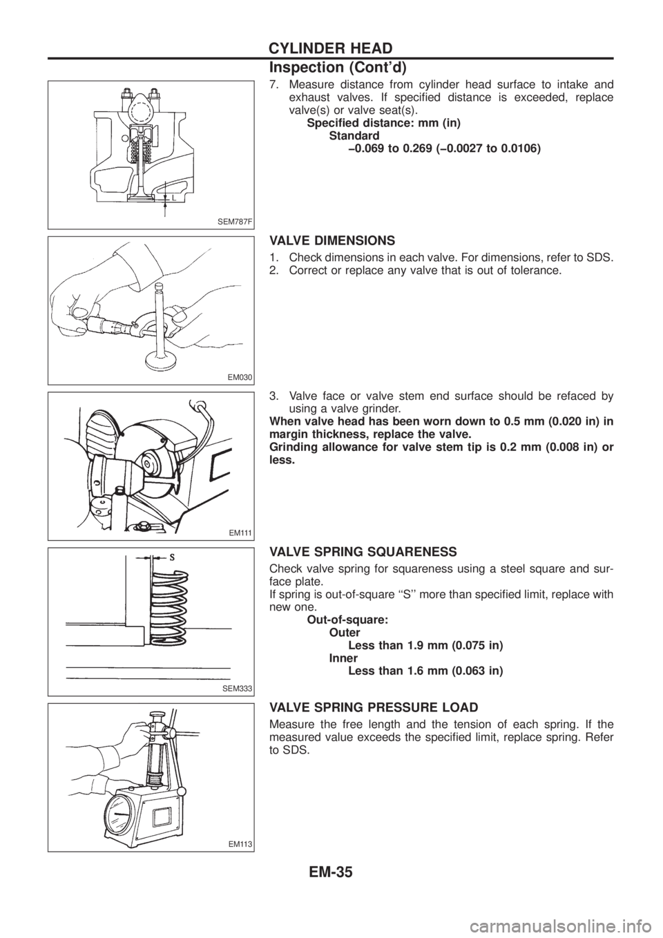
7. Measure distance from cylinder head surface to intake and
exhaust valves. If speci®ed distance is exceeded, replace
valve(s) or valve seat(s).
Speci®ed distance: mm (in)
Standard
þ0.069 to 0.269 (þ0.0027 to 0.0106)
VALVE DIMENSIONS
1. Check dimensions in each valve. For dimensions, refer to SDS.
2. Correct or replace any valve that is out of tolerance.
3. Valve face or valve stem end surface should be refaced by
using a valve grinder.
When valve head has been worn down to 0.5 mm (0.020 in) in
margin thickness, replace the valve.
Grinding allowance for valve stem tip is 0.2 mm (0.008 in) or
less.
VALVE SPRING SQUARENESS
Check valve spring for squareness using a steel square and sur-
face plate.
If spring is out-of-square ``S'' more than speci®ed limit, replace with
new one.
Out-of-square:
Outer
Less than 1.9 mm (0.075 in)
Inner
Less than 1.6 mm (0.063 in)
VALVE SPRING PRESSURE LOAD
Measure the free length and the tension of each spring. If the
measured value exceeds the speci®ed limit, replace spring. Refer
to SDS.
SEM787F
EM030
E M 111
SEM333
EM113
CYLINDER HEAD
Inspection (Cont'd)
EM-35
Page 704 of 1226

VALVE LIFTER
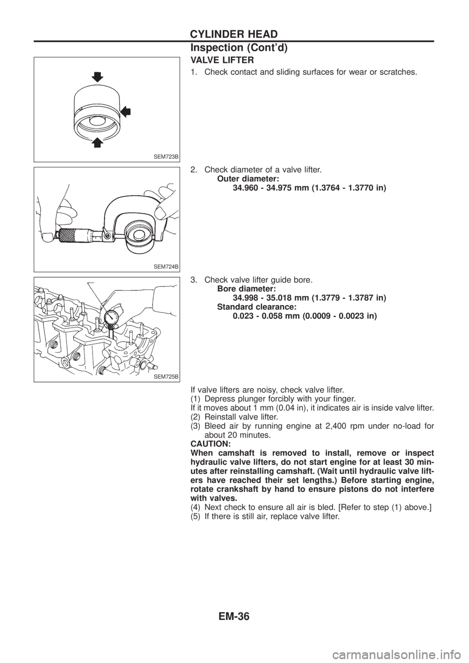
1. Check contact and sliding surfaces for wear or scratches.
2. Check diameter of a valve lifter.
Outer diameter:
34.960 - 34.975 mm (1.3764 - 1.3770 in)
3. Check valve lifter guide bore.
Bore diameter:
34.998 - 35.018 mm (1.3779 - 1.3787 in)
Standard clearance:
0.023 - 0.058 mm (0.0009 - 0.0023 in)
If valve lifters are noisy, check valve lifter.
(1) Depress plunger forcibly with your ®nger.
If it moves about 1 mm (0.04 in), it indicates air is inside valve lifter.
(2) Reinstall valve lifter.
(3) Bleed air by running engine at 2,400 rpm under no-load for
about 20 minutes.
CAUTION:
When camshaft is removed to install, remove or inspect
hydraulic valve lifters, do not start engine for at least 30 min-
utes after reinstalling camshaft. (Wait until hydraulic valve lift-
ers have reached their set lengths.) Before starting engine,
rotate crankshaft by hand to ensure pistons do not interfere
with valves.
(4) Next check to ensure all air is bled. [Refer to step (1) above.]
(5) If there is still air, replace valve lifter.
SEM723B
SEM724B
SEM725B
CYLINDER HEAD
Inspection (Cont'd)
EM-36
Page 716 of 1226

2. Measure outer diameter of piston pin ``Dp''.
Standard diameter ``Dp'':
26.994 - 27.000 mm (1.0628 - 1.0630 in)
3. Calculate piston pin clearance.
dp þ Dp = þ0.004 to 0 mm (þ0.0002 to 0 in)
If it exceeds the above value, replace piston assembly with pin.
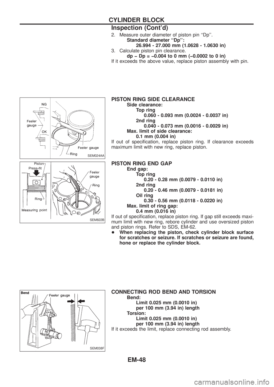
PISTON RING SIDE CLEARANCE
Side clearance:
Top ring
0.060 - 0.093 mm (0.0024 - 0.0037 in)
2nd ring
0.040 - 0.073 mm (0.0016 - 0.0029 in)
Max. limit of side clearance:
0.1 mm (0.004 in)
If out of speci®cation, replace piston ring. If clearance exceeds
maximum limit with new ring, replace piston.
PISTON RING END GAP
End gap:
Top ring
0.20 - 0.28 mm (0.0079 - 0.0110 in)
2nd ring
0.20 - 0.46 mm (0.0079 - 0.0181 in)
Oil ring
0.30 - 0.56 mm (0.0118 - 0.0220 in)
Max. limit of ring gap:
0.4 mm (0.016 in)
If out of speci®cation, replace piston ring. If gap still exceeds maxi-
mum limit with new ring, rebore cylinder and use oversized piston
and piston rings. Refer to SDS, EM-62.
+When replacing the piston, check cylinder block surface
for scratches or seizure. If scratches or seizure are found,
hone or replace the cylinder block.
CONNECTING ROD BEND AND TORSION
Bend:
Limit 0.025 mm (0.0010 in)
per 100 mm (3.94 in) length
Torsion:
Limit 0.025 mm (0.0010 in)
per 100 mm (3.94 in) length
If it exceeds the limit, replace connecting rod assembly.
SEM024AA
SEM822B
SEM038F
CYLINDER BLOCK
Inspection (Cont'd)
EM-48