2006 MERCEDES-BENZ SPRINTER B-pillar
[x] Cancel search: B-pillarPage 993 of 2305

RESTRAINTS
DESCRIPTION
An occupant restraint system is standard factory-
installed safety equipment on this model. Available
occupant restraints for this model include both active
and passive types. Active restraints are those which
require the vehicle occupants to take some action to
employ, such as fastening a seat belt; while passive
restraints require no action by the vehicle occupants
to be employed (Fig. 1).ACTIVE RESTRAINTS
The active restraints for this model include:
²Front Seat Belts- Both outboard front seating
positions are equipped with three-point seat belt sys-
tems employing a lower B-pillar mounted inertia
latch-type retractors, height-adjustable upper B-pil-
lar mounted turning loops, travelling lower seat belt
anchors secured to the outboard seat tracks, and
Fig. 1 Supplemental Restraint System
1 - PASSENGER AIRBAG (OPTIONAL)
2 - SIDE IMPACT SENSOR (2 - WITH OPTIONAL SIDE CURTAIN AIRBAGS ONLY)
3 - DRIVER AIRBAG
4 - AIRBAG CONTROL MODULE
5 - SEAT BELT TENSIONER (DRIVER SIDE - STANDARD, PASSENGER SIDE - OPTIONAL WITH PASSENGER AIRBAG ONLY)
6 - SIDE CURTAIN AIRBAG (2 - OPTIONAL)
8O - 2 RESTRAINTSVA
Page 994 of 2305

travelling end-release seat belt buckles secured to
the inboard seat track. The driver side front seat belt
buckle of all models includes an integral seat belt
switch that detects whether its seat belt has been
fastened.
²Rear Seat Belts- All rear seating positions are
equipped with three-point seat belt systems. Each
rear seating position belt employs an integral seat
cushion frame mounted inertia latch-type retractor, a
fixed position upper seat back frame mounted turn-
ing loop, and a fixed lower seat belt anchor secured
to the seat cushion frame. All rear seat belts have
fixed end-release seat belt buckles that are also
secured to the seat cushion frame.
PASSIVE RESTRAINTS
A Next Generation driver airbag is standard facto-
ry-installed safety equipment on this model, while a
passenger side front airbag and side curtain airbags
are optional. This airbag system is a passive, inflat-
able, Supplemental Restraint System (SRS) and vehi-
cles with this equipment can be readily identified by
the ªSRS - AIRBAGº logo molded into the driver air-
bag trim cover in the center of the steering wheel
and, if the vehicle is so equipped, also into the pas-
senger airbag door on the instrument panel above
the glove box (Fig. 2). Vehicles with the airbag sys-
tem can also be identified by the airbag indicator,
which will illuminate in the instrument cluster for
about six seconds as a bulb test each time the igni-
tion switch is turned to the On position. A pyrotech-
nic-type seat belt tensioner is integral to the front
seat belt retractor mounted on the lower B-pillar on
the driver side, and to the passenger side retractor of
vehicles equipped with the optional passenger side
airbag.
The supplemental restraint system includes the
following major components, which are described in
further detail elsewhere in this service information:²Airbag Control Module- The Airbag Control
Module (ACM) is located on a mount on the floor
panel within the driver side seat riser, beneath the
driver seat in the passenger compartment.
²Airbag (SRS) Indicator- The airbag indicator
is integral to the ElectroMechanical Instrument Clus-
ter (EMIC), which is located on the instrument panel
in front of the driver.
²Clockspring- The clockspring is located near
the top of the steering column, directly beneath the
steering wheel.
²Driver Airbag- The driver airbag is located in
the center of the steering wheel, beneath the driver
airbag trim cover.
²Driver Knee Blocker- The structure of the
lower instrument panel serves as a knee blocker for
the driver.
²Passenger Airbag- The optional passenger air-
bag is located within the instrument panel, behind
the passenger airbag door on the instrument panel
above the glove box on the passenger side of the vehi-
cle.
²Passenger Knee Blocker- The structure of
the glove box door and the lower instrument panel
serve as a knee blocker for the front seat passenger.
²Seat Belt Tensioner- A seat belt tensioner is
integral to the driver side front seat belt retractor
unit, and to the passenger side front seat belt retrac-
tor unit on vehicles equipped with an optional pas-
senger airbag.
²Side Curtain Airbags- Optional side curtain
airbags are available for this model when it is also
equipped with dual front airbags. In vehicles
equipped with this option, a side curtain airbag is
located on the inside of the roof side rail within a
garnish molding that extends from the A-pillar to the
B-pillar above each front door opening within the
passenger compartment of the vehicle.
²Side Impact Sensor- Two side impact sensors
are used on vehicles equipped with the optional side
curtain airbags, one on each side of the vehicle. One
sensor is located near the front of each front door
step well, concealed behind the step well trim.
The ACM contains a central processing unit and
programming that allows it to communicate on a
serial data bus diagnostic circuit connected to the
16-way Data Link Connector (DLC) located below the
left end of the instrument panel. This method of com-
munication is used for initialization of the ACM and
for diagnosis of the SRS circuits and components
using a diagnostic scan tool.
Hard wired circuitry connects the supplemental
restraint system components to each other through
the electrical system of the vehicle. These hard wired
circuits are integral to several wire harnesses, which
are routed throughout the vehicle and retained by
many different methods. These circuits may be con-
nected to each other, to the vehicle electrical system,
Fig. 2 SRS Logo
VARESTRAINTS 8O - 3
Page 1011 of 2305
(1) Position the driver airbag close enough to the
steering wheel to reconnect the clockspring driver
airbag pigtail wire connector at the back of the air-
bag housing.
(2) When installing the driver airbag, reconnect
the clockspring driver airbag pigtail wire connector
to the airbag inflator connector receptacle by press-
ing straight in on the connector (Fig. 21). You can be
certain that the connector is fully engaged by listen-
ing carefully for a distinct, audible click as the con-
nector snaps into place.
(3) Carefully position the driver airbag in the
steering wheel. Be certain that the clockspring pig-
tail wire and horn switch wires in the steering wheel
hub area are not pinched between the driver airbag
and the horn switch armature.
(4) From the underside of the steering wheel,
install and tighten the two screws that secure the
driver airbag to the horn switch armature within the
hub cavity of the steering wheel. Tighten the screws
to 6 N´m (53 in. lbs.).
(5) Do not reconnect the battery negative cable at
this time. The supplemental restraint system verifi-
cation test procedure should be performed following
service of any supplemental restraint system compo-
nent. (Refer to 8 - ELECTRICAL/RESTRAINTS -
STANDARD PROCEDURE - VERIFICATION TEST).
FRONT SEAT BELT & RETRAC-
TOR
REMOVAL
The following procedure is for replacement of a
faulty or damaged front seat belt and retractor unit,
which includes a seat belt tensioner for the driver
side as standard equipment. Vehicles equipped with
an optional passenger airbag also have a seat belt
tensioner for the passenger side. (Refer to 8 - ELEC-
TRICAL/RESTRAINTS/SEAT BELT TENSIONER -
DESCRIPTION). If the seat belt or retractor is faulty
or damaged, but the seat belt tensioner is not
deployed, review the recommended procedures for
handling non-deployed supplemental restraints.
(Refer to 8 - ELECTRICAL/RESTRAINTS - STAN-
DARD PROCEDURE - HANDLING NON-DE-
PLOYED SUPPLEMENTAL RESTRAINTS). If the
seat belt tensioner has been deployed, review the rec-
ommended procedures for service after a supplemen-
tal restraint deployment before removing the front
seat belt and retractor from the vehicle. (Refer to 8 -
ELECTRICAL/RESTRAINTS - STANDARD PROCE-
DURE - SERVICE AFTER A SUPPLEMENTAL
RESTRAINT DEPLOYMENT).
WARNING: To avoid personal injury or death, on
vehicles equipped with airbags, disable the supple-mental restraint system before attempting any
steering wheel, steering column, airbag, seat belt
tensioner, impact sensor, or instrument panel com-
ponent diagnosis or service. Disconnect and isolate
the battery negative (ground) cable, then wait two
minutes for the system capacitor to discharge
before performing further diagnosis or service. This
is the only sure way to disable the supplemental
restraint system. Failure to take the proper precau-
tions could result in accidental airbag deployment.
WARNING: To avoid personal injury or death, during
and following any seat belt service, carefully
inspect all seat belts, buckles, mounting hardware,
retractors, and anchors for proper installation, oper-
ation, or damage. Replace any belt that is cut,
frayed, or torn. Straighten any belt that is twisted.
Tighten any loose fasteners. Replace any belt that
has a damaged or inoperative buckle or retractor.
Replace any belt that has a bent or damaged latch
plate or anchor plate. Never attempt to repair a seat
belt component. Always replace damaged or faulty
seat belt components with the correct, new and
unused replacement parts listed in the
DaimlerChrysler Mopar Parts Catalog.
(1) Move the front seat to its most forward position
for easiest access to the B-pillar trim.
(2) Disconnect and isolate the battery negative
cable. Wait two minutes for the system capacitor to
discharge before further service.
(3) If the vehicle is so equipped, unsnap and
remove the plastic cover from the screw that secures
the front seat belt lower anchor to the outboard side
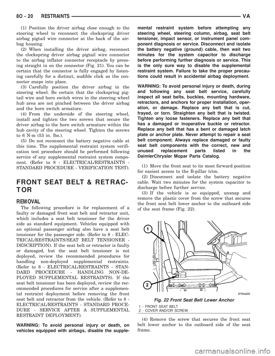
of the seat frame (Fig. 22).
(4) Remove the screw that secures the front seat
belt lower anchor to the outboard side of the seat
frame.
Fig. 22 Front Seat Belt Lower Anchor
1 - FRONT SEAT BELT
2 - COVER AND/OR SCREW
8O - 20 RESTRAINTSVA
Page 1012 of 2305
(5) Remove the front seat belt lower anchor from
the outboard side of the seat frame.
(6) Remove the trim panel from the inside of the
B-pillar. (Refer to 23 - BODY/INTERIOR/B-PILLAR
TRIM - REMOVAL).
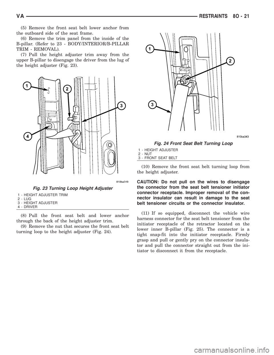
(7) Pull the height adjuster trim away from the
upper B-pillar to disengage the driver from the lug of
the height adjuster (Fig. 23).
(8) Pull the front seat belt and lower anchor
through the back of the height adjuster trim.
(9) Remove the nut that secures the front seat belt
turning loop to the height adjuster (Fig. 24).(10) Remove the front seat belt turning loop from
the height adjuster.
CAUTION: Do not pull on the wires to disengage
the connector from the seat belt tensioner initiator
connector receptacle. Improper removal of the con-
nector insulator can result in damage to the seat
belt tensioner circuits or the connector insulator.
(11) If so equipped, disconnect the vehicle wire
harness connector for the seat belt tensioner from the
initiator receptacle of the retractor located on the
lower inner B-pillar (Fig. 25). The connector is a
tight snap-fit into the initiator receptacle. Firmly
grasp and pull or gently pry on the connector insula-
tor and pull the connector straight out from the ini-
tiator to disconnect it from the receptacle.
Fig. 23 Turning Loop Height Adjuster
1 - HEIGHT ADJUSTER TRIM
2 - LUG
3 - HEIGHT ADJUSTER
4 - DRIVER
Fig. 24 Front Seat Belt Turning Loop
1 - HEIGHT ADJUSTER
2 - NUT
3 - FRONT SEAT BELT
VARESTRAINTS 8O - 21
Page 1013 of 2305
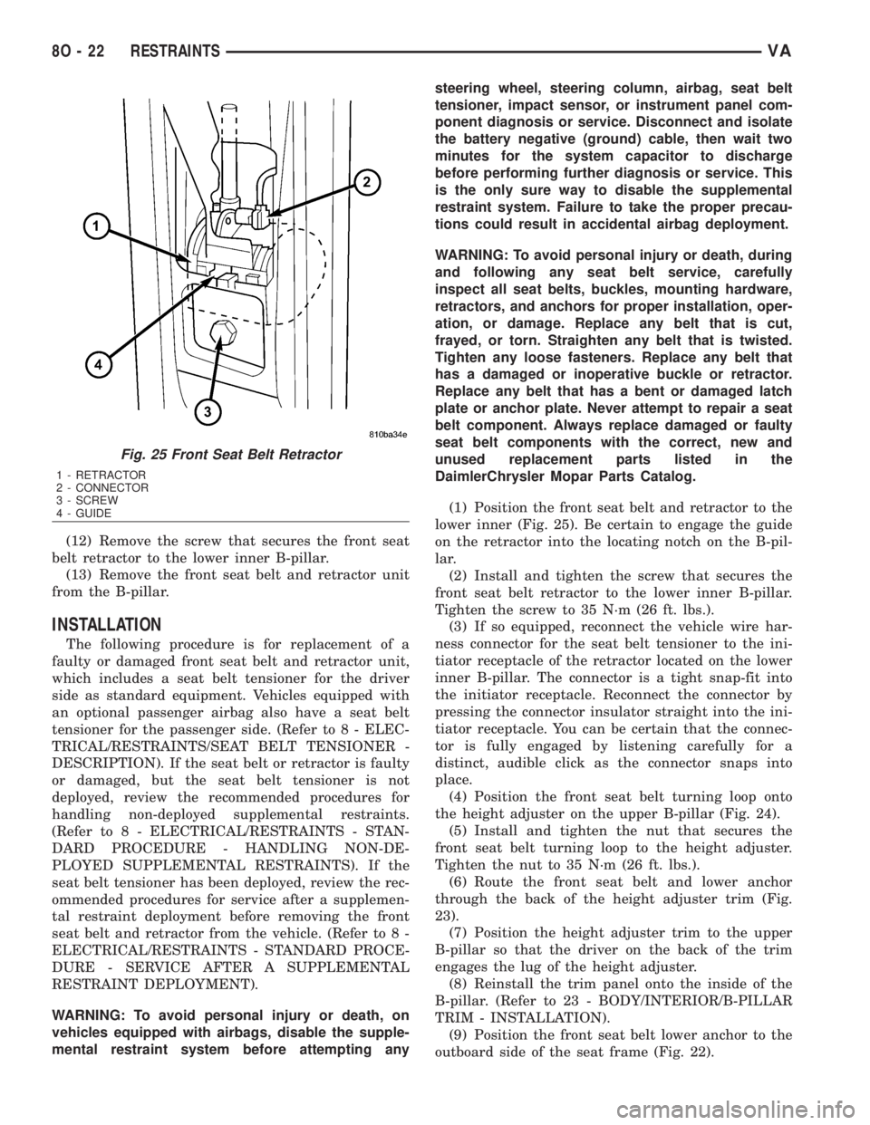
(12) Remove the screw that secures the front seat
belt retractor to the lower inner B-pillar.
(13) Remove the front seat belt and retractor unit
from the B-pillar.
INSTALLATION
The following procedure is for replacement of a
faulty or damaged front seat belt and retractor unit,
which includes a seat belt tensioner for the driver
side as standard equipment. Vehicles equipped with
an optional passenger airbag also have a seat belt
tensioner for the passenger side. (Refer to 8 - ELEC-
TRICAL/RESTRAINTS/SEAT BELT TENSIONER -
DESCRIPTION). If the seat belt or retractor is faulty
or damaged, but the seat belt tensioner is not
deployed, review the recommended procedures for
handling non-deployed supplemental restraints.
(Refer to 8 - ELECTRICAL/RESTRAINTS - STAN-
DARD PROCEDURE - HANDLING NON-DE-
PLOYED SUPPLEMENTAL RESTRAINTS). If the
seat belt tensioner has been deployed, review the rec-
ommended procedures for service after a supplemen-
tal restraint deployment before removing the front
seat belt and retractor from the vehicle. (Refer to 8 -
ELECTRICAL/RESTRAINTS - STANDARD PROCE-
DURE - SERVICE AFTER A SUPPLEMENTAL
RESTRAINT DEPLOYMENT).
WARNING: To avoid personal injury or death, on
vehicles equipped with airbags, disable the supple-
mental restraint system before attempting anysteering wheel, steering column, airbag, seat belt
tensioner, impact sensor, or instrument panel com-
ponent diagnosis or service. Disconnect and isolate
the battery negative (ground) cable, then wait two
minutes for the system capacitor to discharge
before performing further diagnosis or service. This
is the only sure way to disable the supplemental
restraint system. Failure to take the proper precau-
tions could result in accidental airbag deployment.
WARNING: To avoid personal injury or death, during
and following any seat belt service, carefully
inspect all seat belts, buckles, mounting hardware,
retractors, and anchors for proper installation, oper-
ation, or damage. Replace any belt that is cut,
frayed, or torn. Straighten any belt that is twisted.
Tighten any loose fasteners. Replace any belt that
has a damaged or inoperative buckle or retractor.
Replace any belt that has a bent or damaged latch
plate or anchor plate. Never attempt to repair a seat
belt component. Always replace damaged or faulty
seat belt components with the correct, new and
unused replacement parts listed in the
DaimlerChrysler Mopar Parts Catalog.
(1) Position the front seat belt and retractor to the
lower inner (Fig. 25). Be certain to engage the guide
on the retractor into the locating notch on the B-pil-
lar.
(2) Install and tighten the screw that secures the
front seat belt retractor to the lower inner B-pillar.
Tighten the screw to 35 N´m (26 ft. lbs.).
(3) If so equipped, reconnect the vehicle wire har-
ness connector for the seat belt tensioner to the ini-
tiator receptacle of the retractor located on the lower
inner B-pillar. The connector is a tight snap-fit into
the initiator receptacle. Reconnect the connector by
pressing the connector insulator straight into the ini-
tiator receptacle. You can be certain that the connec-
tor is fully engaged by listening carefully for a
distinct, audible click as the connector snaps into
place.
(4) Position the front seat belt turning loop onto
the height adjuster on the upper B-pillar (Fig. 24).
(5) Install and tighten the nut that secures the
front seat belt turning loop to the height adjuster.
Tighten the nut to 35 N´m (26 ft. lbs.).
(6) Route the front seat belt and lower anchor
through the back of the height adjuster trim (Fig.
23).
(7) Position the height adjuster trim to the upper
B-pillar so that the driver on the back of the trim
engages the lug of the height adjuster.
(8) Reinstall the trim panel onto the inside of the
B-pillar. (Refer to 23 - BODY/INTERIOR/B-PILLAR
TRIM - INSTALLATION).
(9) Position the front seat belt lower anchor to the
outboard side of the seat frame (Fig. 22).
Fig. 25 Front Seat Belt Retractor
1 - RETRACTOR
2 - CONNECTOR
3 - SCREW
4 - GUIDE
8O - 22 RESTRAINTSVA
Page 1023 of 2305
out and connector of the vehicle wire harness located
within the driver side front seat riser.
The seat belt switch cannot be adjusted or repaired
and, if faulty or damaged, the entire driver side seat
belt buckle unit must be replaced.
OPERATION
The seat belt switch is designed to control a path
to ground for the seat belt switch sense input of the
Electro-Mechanical Instrument Cluster (EMIC). The
seat belt switch contact is actuated by the seat belt
latch plate being inserted in to the buckle. When the
seat belt latch plate is inserted into the buckle far
enough to be engaged by the seat belt buckle latch,
the switch leaf contact opens the seat belt switch
sense circuit ground path; and, when the seat belt
latch plate is released and extracted from the seat
belt buckle latch the switch leaf contact is released,
closing the circuit to ground.
The seat belt switch is connected is series between
ground and the seat belt switch sense input of the
instrument cluster. The seat belt switch receives
ground at all times through its pigtail wire connec-
tion to the vehicle wire harness from another take
out of the vehicle wire harness. An eyelet terminal
connector on the vehicle wire harness ground take
out is secured under a nut to a ground stud located
on the floor panel within the driver side front seat
riser. The seat belt switch may de diagnosed using
conventional diagnostic tools and methods.
SEAT BELT TENSIONER
DESCRIPTION
Front seating position seat belt tensioners supple-
ment the standard driver and optional passenger air-
bags for all versions of this model. When equipped,
the seat belt tensioner is integral to the front seat
belt and retractor units, which are secured to the
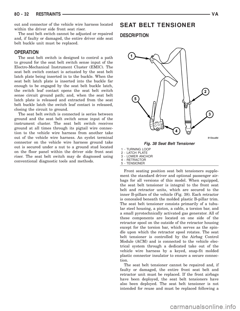
inner B-pillars of the vehicle (Fig. 38). Each retractor
is concealed beneath the molded plastic B-pillar trim.
The seat belt tensioner consists primarily of a tubu-
lar steel housing, a piston, a cable, a torsion bar, and
a small pyrotechnically activated gas generator. All of
these components are located on one side of the
retractor spool on the outside of the retractor housing
except for the torsion bar, which serves as the spin-
dle upon which the retractor spool rotates. The seat
belt tensioner is controlled by the Airbag Control
Module (ACM) and is connected to the vehicle elec-
trical system through a dedicated take out of the
vehicle wire harness by a keyed, snap-fit molded
plastic connector insulator to ensure a secure connec-
tion.
The seat belt tensioner cannot be repaired and, if
faulty or damaged, the entire front seat belt and
retractor unit must be replaced. If the front airbags
have been deployed, the seat belt tensioners have
also been deployed. The seat belt tensioner is not
intended for reuse and must be replaced following a
Fig. 38 Seat Belt Tensioner
1 - TURNING LOOP
2 - LATCH PLATE
3 - LOWER ANCHOR
4 - RETRACTOR
5 - TENSIONER
8O - 32 RESTRAINTSVA
Page 1024 of 2305
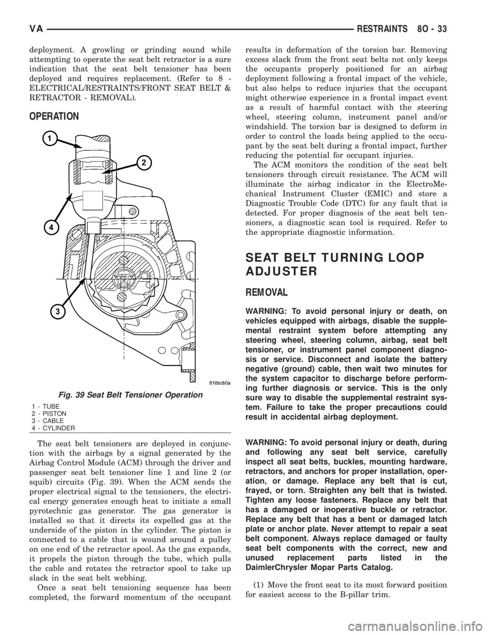
deployment. A growling or grinding sound while
attempting to operate the seat belt retractor is a sure
indication that the seat belt tensioner has been
deployed and requires replacement. (Refer to 8 -
ELECTRICAL/RESTRAINTS/FRONT SEAT BELT &
RETRACTOR - REMOVAL).
OPERATION
The seat belt tensioners are deployed in conjunc-
tion with the airbags by a signal generated by the
Airbag Control Module (ACM) through the driver and
passenger seat belt tensioner line 1 and line 2 (or
squib) circuits (Fig. 39). When the ACM sends the
proper electrical signal to the tensioners, the electri-
cal energy generates enough heat to initiate a small
pyrotechnic gas generator. The gas generator is
installed so that it directs its expelled gas at the
underside of the piston in the cylinder. The piston is
connected to a cable that is wound around a pulley
on one end of the retractor spool. As the gas expands,
it propels the piston through the tube, which pulls
the cable and rotates the retractor spool to take up
slack in the seat belt webbing.
Once a seat belt tensioning sequence has been
completed, the forward momentum of the occupantresults in deformation of the torsion bar. Removing
excess slack from the front seat belts not only keeps
the occupants properly positioned for an airbag
deployment following a frontal impact of the vehicle,
but also helps to reduce injuries that the occupant
might otherwise experience in a frontal impact event
as a result of harmful contact with the steering
wheel, steering column, instrument panel and/or
windshield. The torsion bar is designed to deform in
order to control the loads being applied to the occu-
pant by the seat belt during a frontal impact, further
reducing the potential for occupant injuries.
The ACM monitors the condition of the seat belt
tensioners through circuit resistance. The ACM will
illuminate the airbag indicator in the ElectroMe-
chanical Instrument Cluster (EMIC) and store a
Diagnostic Trouble Code (DTC) for any fault that is
detected. For proper diagnosis of the seat belt ten-
sioners, a diagnostic scan tool is required. Refer to
the appropriate diagnostic information.
SEAT BELT TURNING LOOP
ADJUSTER
REMOVAL
WARNING: To avoid personal injury or death, on
vehicles equipped with airbags, disable the supple-
mental restraint system before attempting any
steering wheel, steering column, airbag, seat belt
tensioner, or instrument panel component diagno-
sis or service. Disconnect and isolate the battery
negative (ground) cable, then wait two minutes for
the system capacitor to discharge before perform-
ing further diagnosis or service. This is the only
sure way to disable the supplemental restraint sys-
tem. Failure to take the proper precautions could
result in accidental airbag deployment.
WARNING: To avoid personal injury or death, during
and following any seat belt service, carefully
inspect all seat belts, buckles, mounting hardware,
retractors, and anchors for proper installation, oper-
ation, or damage. Replace any belt that is cut,
frayed, or torn. Straighten any belt that is twisted.
Tighten any loose fasteners. Replace any belt that
has a damaged or inoperative buckle or retractor.
Replace any belt that has a bent or damaged latch
plate or anchor plate. Never attempt to repair a seat
belt component. Always replace damaged or faulty
seat belt components with the correct, new and
unused replacement parts listed in the
DaimlerChrysler Mopar Parts Catalog.
(1) Move the front seat to its most forward position
for easiest access to the B-pillar trim.
Fig. 39 Seat Belt Tensioner Operation
1 - TUBE
2 - PISTON
3 - CABLE
4 - CYLINDER
VARESTRAINTS 8O - 33
Page 1025 of 2305

(2) Disconnect and isolate the battery negative
cable. Wait two minutes for the system capacitor to
discharge before further service.
(3) Remove the trim panel from the inside of the
B-pillar. (Refer to 23 - BODY/INTERIOR/B-PILLAR
TRIM - REMOVAL).
(4) Pull the height adjuster trim away from the
upper B-pillar to disengage the driver from the lug of
the height adjuster (Fig. 40).
(5) Remove the nut that secures the front seat belt
turning loop to the height adjuster (Fig. 41).(6) Remove the front seat belt turning loop from
the height adjuster.
(7) Remove the two screws that secure the seat
belt turning loop height adjuster to the upper inner
B-pillar (Fig. 42).
Fig. 40 Turning Loop Height Adjuster
1 - HEIGHT ADJUSTER TRIM
2 - LUG
3 - HEIGHT ADJUSTER
4 - DRIVER
Fig. 41 Front Seat Belt Turning Loop
1 - HEIGHT ADJUSTER
2 - NUT
3 - FRONT SEAT BELT
Fig. 42 Seat Belt Turning Loop Adjuster Remove/
Install
1 - SCREW (2)
2 - ADJUSTER
3 - B-PILLAR
8O - 34 RESTRAINTSVA