2006 MERCEDES-BENZ SPRINTER B-pillar
[x] Cancel search: B-pillarPage 1026 of 2305
(8) Remove the seat belt turning loop height
adjuster from the inner B-pillar.
INSTALLATION
WARNING: To avoid personal injury or death, on
vehicles equipped with airbags, disable the supple-
mental restraint system before attempting any
steering wheel, steering column, airbag, seat belt
tensioner, or instrument panel component diagno-
sis or service. Disconnect and isolate the battery
negative (ground) cable, then wait two minutes for
the system capacitor to discharge before perform-
ing further diagnosis or service. This is the only
sure way to disable the supplemental restraint sys-
tem. Failure to take the proper precautions could
result in accidental airbag deployment.
WARNING: To avoid personal injury or death, during
and following any seat belt service, carefully
inspect all seat belts, buckles, mounting hardware,
retractors, and anchors for proper installation, oper-
ation, or damage. Replace any belt that is cut,
frayed, or torn. Straighten any belt that is twisted.
Tighten any loose fasteners. Replace any belt that
has a damaged or inoperative buckle or retractor.
Replace any belt that has a bent or damaged latch
plate or anchor plate. Never attempt to repair a seat
belt component. Always replace damaged or faulty
seat belt components with the correct, new and
unused replacement parts listed in the
DaimlerChrysler Mopar Parts Catalog.
(1) Position the seat belt turning loop height
adjuster onto the inner B-pillar (Fig. 42).
(2) Install and tighten the two screws that secure
the seat belt turning loop height adjuster to the
upper inner B-pillar. Tighten the screws to 35 N´m
(26 ft. lbs.).
(3) Position the front seat belt turning loop onto
the height adjuster on the upper B-pillar (Fig. 41).
(4) Install and tighten the nut that secures the
front seat belt turning loop to the height adjuster.
Tighten the nut to 35 N´m (26 ft. lbs.).
(5) Position the height adjuster trim to the upper
B-pillar so that the driver on the back of the trim
engages the lug of the height adjuster (Fig. 40).
(6) Reinstall the trim panel onto the inside of the
B-pillar. (Refer to 23 - BODY/INTERIOR/B-PILLAR
TRIM - INSTALLATION).
(7) Reconnect the battery negative cable.
SIDE CURTAIN AIRBAG
DESCRIPTION
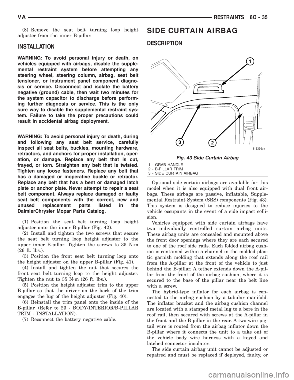
Optional side curtain airbags are available for this
model when it is also equipped with dual front air-
bags. These airbags are passive, inflatable, Supple-
mental Restraint System (SRS) components (Fig. 43).
This system is designed to reduce injuries to the
vehicle occupants in the event of a side impact colli-
sion.
Vehicles equipped with side curtain airbags have
two individually controlled curtain airbag units.
These airbag units are concealed and mounted above
the front door openings where they are each secured
to one of the roof side rails. Each folded airbag cush-
ion is contained within a channel in the molded plas-
tic garnish molding that extends along the roof rail
from the A-pillar at the front of the vehicle to just
behind the B-pillar. A tether extends down the A-pil-
lar from the front of the airbag cushion, where it is
secured to the base of the pillar near the belt line
with a screw.
The hybrid-type inflator for each airbag is con-
nected to the airbag cushion by a tubular manifold.
The inflator bracket and the airbag cushion channel
are located with a stamped metal lug to a bore in the
roof rail, then secured with screws at the A-pillar in
the front and the B-pillar in the rear. A two-wire pig-
tail wire is routed from the airbag inflator down the
B-pillar where it connects the unit to a take out of
the vehicle body wire harness with a keyed and
latched connector insulator.
The side curtain airbag unit cannot be adjusted or
repaired and must be replaced if deployed, faulty, or
Fig. 43 Side Curtain Airbag
1 - GRAB HANDLE
2 - B-PILLAR TRIM
3 - SIDE CURTAIN AIRBAG
VARESTRAINTS 8O - 35
Page 1027 of 2305
in any way damaged. Once a side curtain airbag has
been deployed, the complete airbag unit and all other
visibly damaged components must be replaced.
OPERATION
Each side curtain airbag is deployed individually
by an electrical signal generated by the Airbag Con-
trol Module (ACM) to which it is connected through
left or right curtain airbag line 1 and line 2 (or
squib) circuits. The hybrid-type inflator assembly for
each airbag contains a small canister of highly com-
pressed inert gas. When the ACM sends the proper
electrical signal to the airbag inflator, the electrical
energy creates enough heat to ignite chemical pellets
within the inflator. Once ignited, these chemicals
burn rapidly and produce the pressure necessary to
rupture a containment disk in the inert gas canister.
The inflator and inert gas canister are sealed and
connected to a tubular manifold so that all of the
released gas is directed into the folded side curtain
airbag cushion, causing the cushion to inflate.
As the airbag cushion inflates it will split the gar-
nish molding at a predetermined breakout line and
drop down from the roof rail along the side glass and
body pillars to form a curtain-like cushion to protect
the vehicle occupants during a side impact collision.
The front tether keeps the front portion of the side
curtain bag taut, thus ensuring that the bag will
deploy in the proper position. Following the airbag
deployment, the airbag cushion quickly deflates by
venting the inert gas through the loose weave of the
cushion fabric, and the deflated cushion hangs down
loosely from the roof rail.
REMOVAL
The following procedure is for replacement of a
faulty or damaged side curtain airbag. If the airbag
is faulty or damaged, but not deployed, review the
recommended procedures for handling non-deployed
supplemental restraints. (Refer to 8 - ELECTRICAL/
RESTRAINTS - STANDARD PROCEDURE - HAN-
DLING NON-DEPLOYED SUPPLEMENTAL
RESTRAINTS). If the side curtain airbag has been
deployed, review the recommended procedures for
service after a supplemental restraint deployment
before removing the airbag from the vehicle. (Refer to
8 - ELECTRICAL/RESTRAINTS - STANDARD PRO-
CEDURE - SERVICE AFTER A SUPPLEMENTAL
RESTRAINT DEPLOYMENT).
WARNING: To avoid personal injury or death, on
vehicles equipped with airbags, disable the supple-
mental restraint system before attempting any
steering wheel, steering column, airbag, seat belt
tensioner, impact sensor, or instrument panel com-
ponent diagnosis or service. Disconnect and isolate
the battery negative (ground) cable, then wait two
minutes for the system capacitor to dischargebefore performing further diagnosis or service. This
is the only sure way to disable the supplemental
restraint system. Failure to take the proper precau-
tions could result in accidental airbag deployment.
WARNING: To avoid personal injury or death, when
removing a deployed airbag, rubber gloves, eye
protection, and a long-sleeved shirt should be
worn. There may be deposits on the airbag unit and
other interior surfaces. In large doses, these depos-
its may cause irritation to the skin and eyes.
WARNING: To avoid personal injury or death, use
extreme care to prevent any foreign material from
entering the side curtain airbag, or becoming
entrapped between the side curtain airbag cushion
and the roof rail garnish molding. Failure to
observe this warning could result in occupant inju-
ries upon airbag deployment.
(1) Disconnect and isolate the battery negative
cable. Wait two minutes for the system capacitor to
discharge before further service.
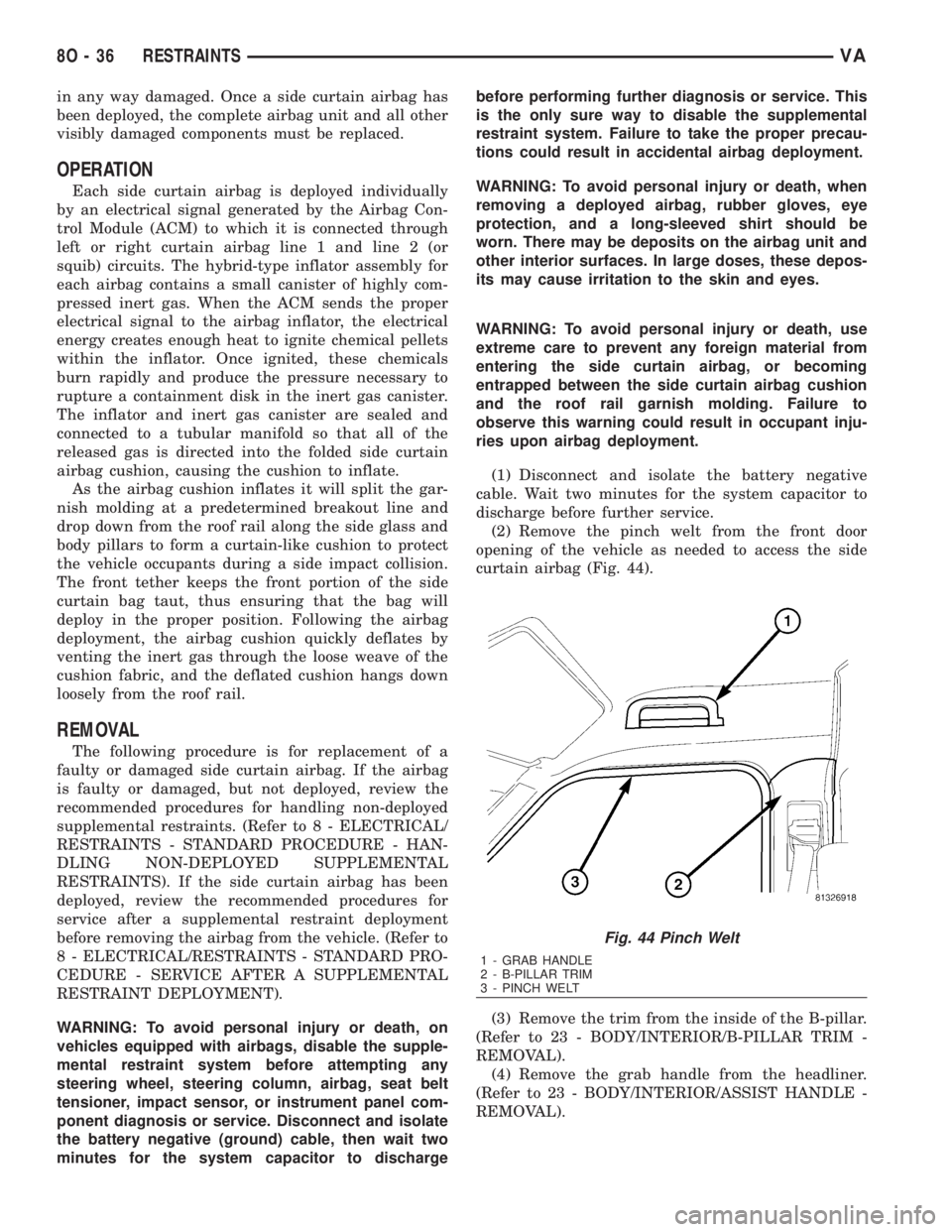
(2) Remove the pinch welt from the front door
opening of the vehicle as needed to access the side
curtain airbag (Fig. 44).
(3) Remove the trim from the inside of the B-pillar.
(Refer to 23 - BODY/INTERIOR/B-PILLAR TRIM -
REMOVAL).
(4) Remove the grab handle from the headliner.
(Refer to 23 - BODY/INTERIOR/ASSIST HANDLE -
REMOVAL).
Fig. 44 Pinch Welt
1 - GRAB HANDLE
2 - B-PILLAR TRIM
3 - PINCH WELT
8O - 36 RESTRAINTSVA
Page 1028 of 2305
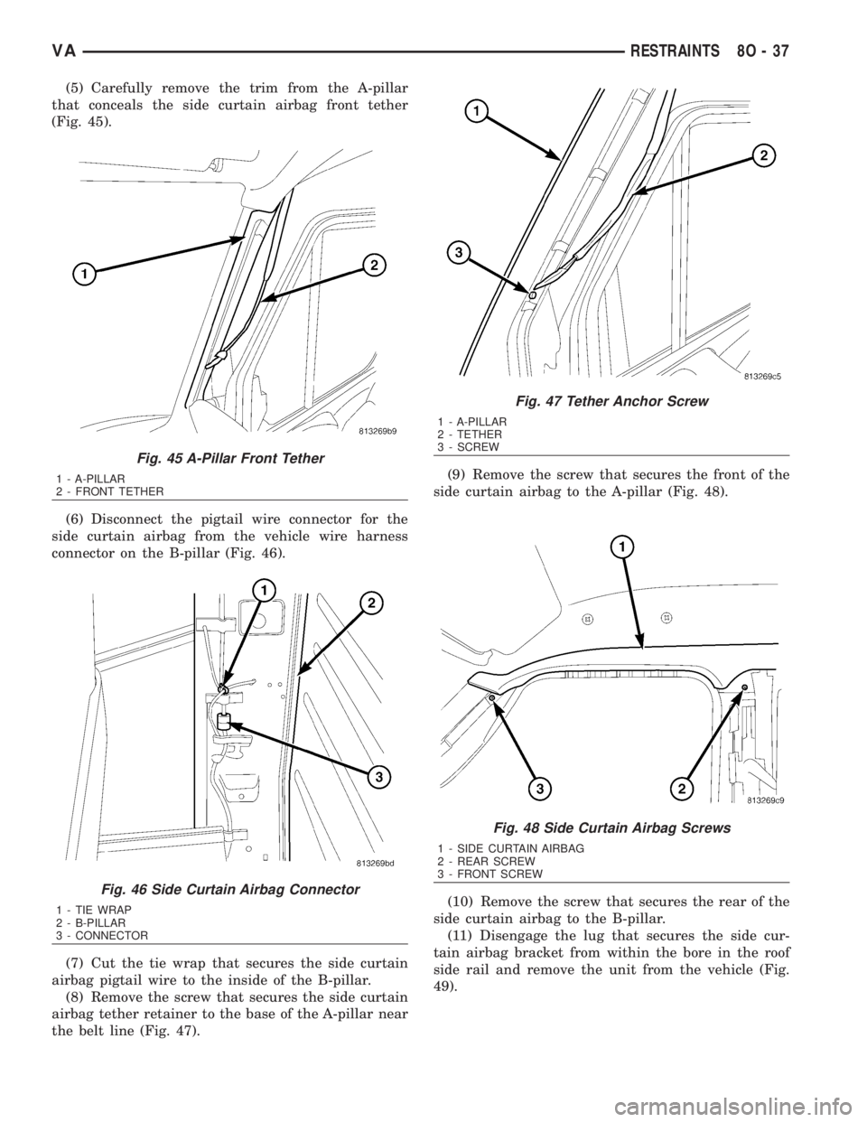
(5) Carefully remove the trim from the A-pillar
that conceals the side curtain airbag front tether
(Fig. 45).
(6) Disconnect the pigtail wire connector for the
side curtain airbag from the vehicle wire harness
connector on the B-pillar (Fig. 46).
(7) Cut the tie wrap that secures the side curtain
airbag pigtail wire to the inside of the B-pillar.
(8) Remove the screw that secures the side curtain
airbag tether retainer to the base of the A-pillar near
the belt line (Fig. 47).(9) Remove the screw that secures the front of the
side curtain airbag to the A-pillar (Fig. 48).
(10) Remove the screw that secures the rear of the
side curtain airbag to the B-pillar.
(11) Disengage the lug that secures the side cur-
tain airbag bracket from within the bore in the roof
side rail and remove the unit from the vehicle (Fig.
49).
Fig. 45 A-Pillar Front Tether
1 - A-PILLAR
2 - FRONT TETHER
Fig. 46 Side Curtain Airbag Connector
1 - TIE WRAP
2 - B-PILLAR
3 - CONNECTOR
Fig. 47 Tether Anchor Screw
1 - A-PILLAR
2 - TETHER
3 - SCREW
Fig. 48 Side Curtain Airbag Screws
1 - SIDE CURTAIN AIRBAG
2 - REAR SCREW
3 - FRONT SCREW
VARESTRAINTS 8O - 37
Page 1029 of 2305
INSTALLATION
The following procedure is for replacement of a
faulty or damaged side curtain airbag. If the airbag
is faulty or damaged, but not deployed, review the
recommended procedures for handling non-deployed
supplemental restraints. (Refer to 8 - ELECTRICAL/
RESTRAINTS - STANDARD PROCEDURE - HAN-
DLING NON-DEPLOYED SUPPLEMENTAL
RESTRAINTS). If the side curtain airbag has been
deployed, review the recommended procedures for
service after a supplemental restraint deployment
before removing the airbag from the vehicle. (Refer to
8 - ELECTRICAL/RESTRAINTS - STANDARD PRO-
CEDURE - SERVICE AFTER A SUPPLEMENTAL
RESTRAINT DEPLOYMENT).
WARNING: To avoid personal injury or death, on
vehicles equipped with airbags, disable the supple-
mental restraint system before attempting any
steering wheel, steering column, airbag, seat belt
tensioner, impact sensor, or instrument panel com-
ponent diagnosis or service. Disconnect and isolate
the battery negative (ground) cable, then wait two
minutes for the system capacitor to discharge
before performing further diagnosis or service. This
is the only sure way to disable the supplemental
restraint system. Failure to take the proper precau-
tions could result in accidental airbag deployment.
WARNING: To avoid personal injury or death, when
removing a deployed airbag, rubber gloves, eye
protection, and a long-sleeved shirt should be
worn. There may be deposits on the airbag unit and
other interior surfaces. In large doses, these depos-
its may cause irritation to the skin and eyes.WARNING: To avoid personal injury or death, use
extreme care to prevent any foreign material from
entering the side curtain airbag, or becoming
entrapped between the side curtain airbag cushion
and the roof rail garnish molding. Failure to
observe this warning could result in occupant inju-
ries upon airbag deployment.
(1) Position the side curtain airbag into the vehicle
as a unit.
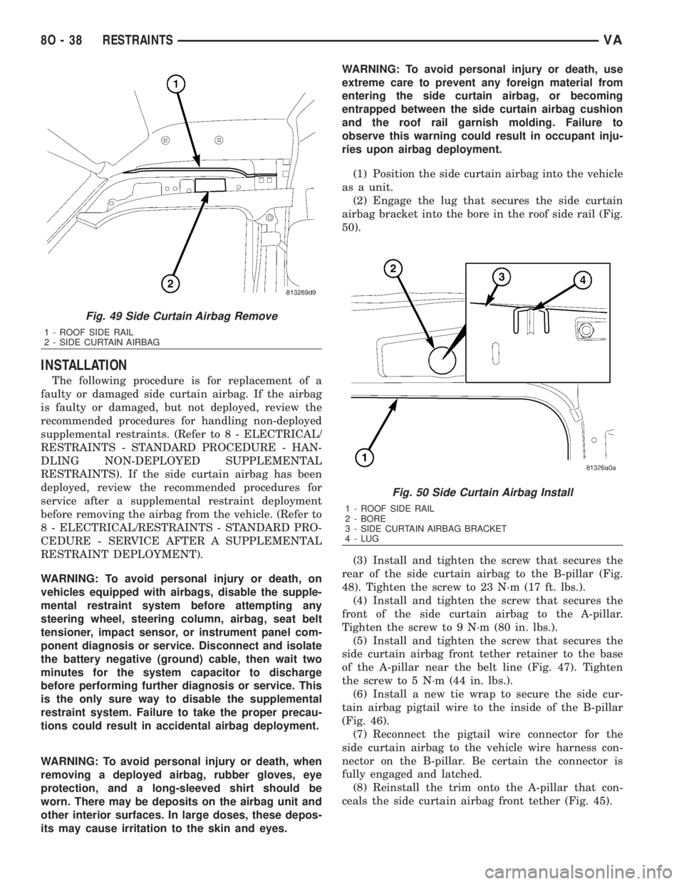
(2) Engage the lug that secures the side curtain
airbag bracket into the bore in the roof side rail (Fig.
50).
(3) Install and tighten the screw that secures the
rear of the side curtain airbag to the B-pillar (Fig.
48). Tighten the screw to 23 N´m (17 ft. lbs.).
(4) Install and tighten the screw that secures the
front of the side curtain airbag to the A-pillar.
Tighten the screw to 9 N´m (80 in. lbs.).
(5) Install and tighten the screw that secures the
side curtain airbag front tether retainer to the base
of the A-pillar near the belt line (Fig. 47). Tighten
the screw to 5 N´m (44 in. lbs.).
(6) Install a new tie wrap to secure the side cur-
tain airbag pigtail wire to the inside of the B-pillar
(Fig. 46).
(7) Reconnect the pigtail wire connector for the
side curtain airbag to the vehicle wire harness con-
nector on the B-pillar. Be certain the connector is
fully engaged and latched.
(8) Reinstall the trim onto the A-pillar that con-
ceals the side curtain airbag front tether (Fig. 45).
Fig. 49 Side Curtain Airbag Remove
1 - ROOF SIDE RAIL
2 - SIDE CURTAIN AIRBAG
Fig. 50 Side Curtain Airbag Install
1 - ROOF SIDE RAIL
2 - BORE
3 - SIDE CURTAIN AIRBAG BRACKET
4 - LUG
8O - 38 RESTRAINTSVA
Page 1030 of 2305
(9) Reinstall the grab handle onto the headliner.
(Refer to 23 - BODY/INTERIOR/ASSIST HANDLE -
INSTALLATION).
(10) Reinstall the trim onto the inside of the B-pil-
lar. (Refer to 23 - BODY/INTERIOR/B-PILLAR TRIM
- INSTALLATION).
(11) Reinstall the pinch welt to the front door
opening (Fig. 44).
(12) Do not reconnect the battery negative cable at
this time. The supplemental restraint system verifi-
cation test procedure should be performed following
service of any supplemental restraint system compo-
nent. (Refer to 8 - ELECTRICAL/RESTRAINTS -
STANDARD PROCEDURE - VERIFICATION TEST).
SIDE IMPACT SENSOR
DESCRIPTION
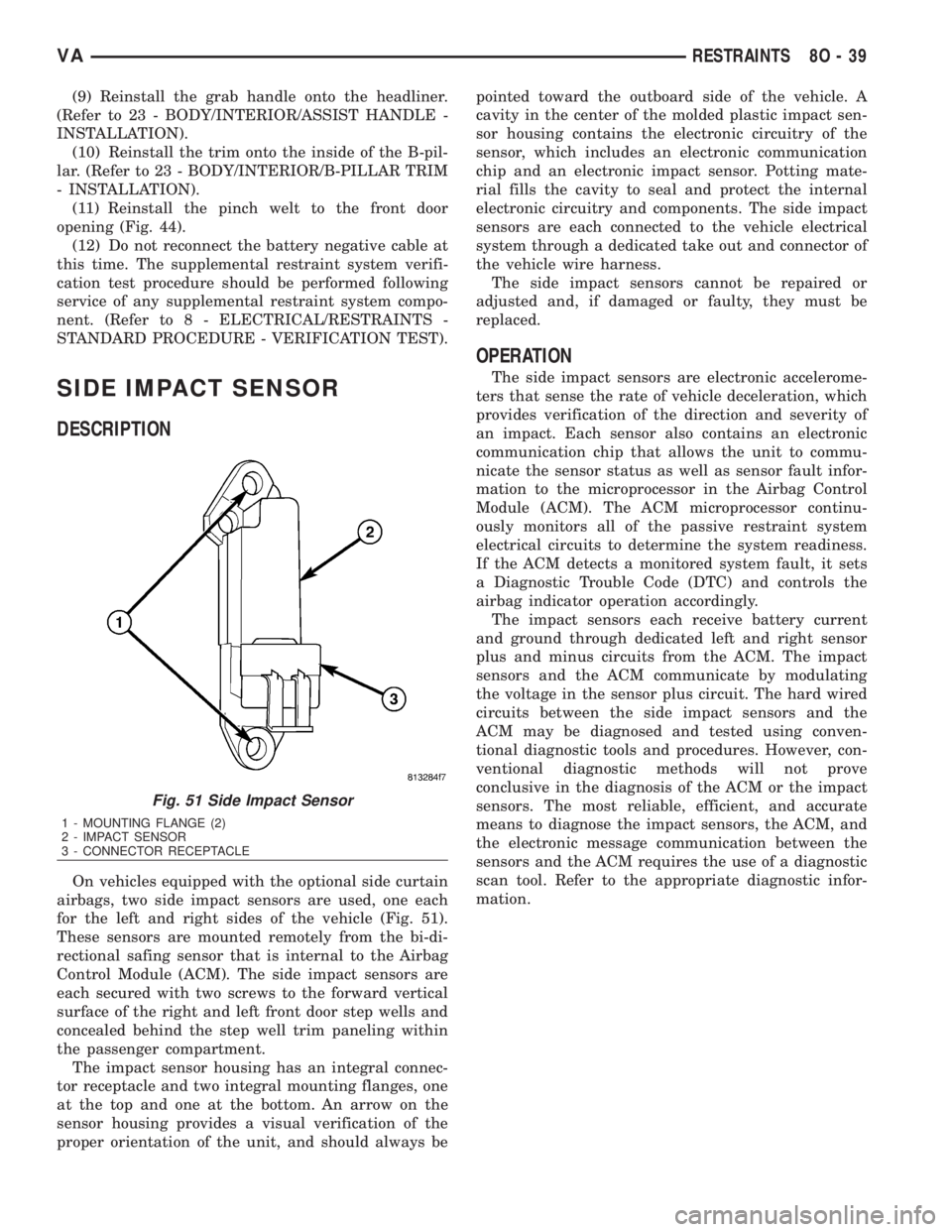
On vehicles equipped with the optional side curtain
airbags, two side impact sensors are used, one each
for the left and right sides of the vehicle (Fig. 51).
These sensors are mounted remotely from the bi-di-
rectional safing sensor that is internal to the Airbag
Control Module (ACM). The side impact sensors are
each secured with two screws to the forward vertical
surface of the right and left front door step wells and
concealed behind the step well trim paneling within
the passenger compartment.
The impact sensor housing has an integral connec-
tor receptacle and two integral mounting flanges, one
at the top and one at the bottom. An arrow on the
sensor housing provides a visual verification of the
proper orientation of the unit, and should always bepointed toward the outboard side of the vehicle. A
cavity in the center of the molded plastic impact sen-
sor housing contains the electronic circuitry of the
sensor, which includes an electronic communication
chip and an electronic impact sensor. Potting mate-
rial fills the cavity to seal and protect the internal
electronic circuitry and components. The side impact
sensors are each connected to the vehicle electrical
system through a dedicated take out and connector of
the vehicle wire harness.
The side impact sensors cannot be repaired or
adjusted and, if damaged or faulty, they must be
replaced.
OPERATION
The side impact sensors are electronic accelerome-
ters that sense the rate of vehicle deceleration, which
provides verification of the direction and severity of
an impact. Each sensor also contains an electronic
communication chip that allows the unit to commu-
nicate the sensor status as well as sensor fault infor-
mation to the microprocessor in the Airbag Control
Module (ACM). The ACM microprocessor continu-
ously monitors all of the passive restraint system
electrical circuits to determine the system readiness.
If the ACM detects a monitored system fault, it sets
a Diagnostic Trouble Code (DTC) and controls the
airbag indicator operation accordingly.
The impact sensors each receive battery current
and ground through dedicated left and right sensor
plus and minus circuits from the ACM. The impact
sensors and the ACM communicate by modulating
the voltage in the sensor plus circuit. The hard wired
circuits between the side impact sensors and the
ACM may be diagnosed and tested using conven-
tional diagnostic tools and procedures. However, con-
ventional diagnostic methods will not prove
conclusive in the diagnosis of the ACM or the impact
sensors. The most reliable, efficient, and accurate
means to diagnose the impact sensors, the ACM, and
the electronic message communication between the
sensors and the ACM requires the use of a diagnostic
scan tool. Refer to the appropriate diagnostic infor-
mation.
Fig. 51 Side Impact Sensor
1 - MOUNTING FLANGE (2)
2 - IMPACT SENSOR
3 - CONNECTOR RECEPTACLE
VARESTRAINTS 8O - 39
Page 1506 of 2305
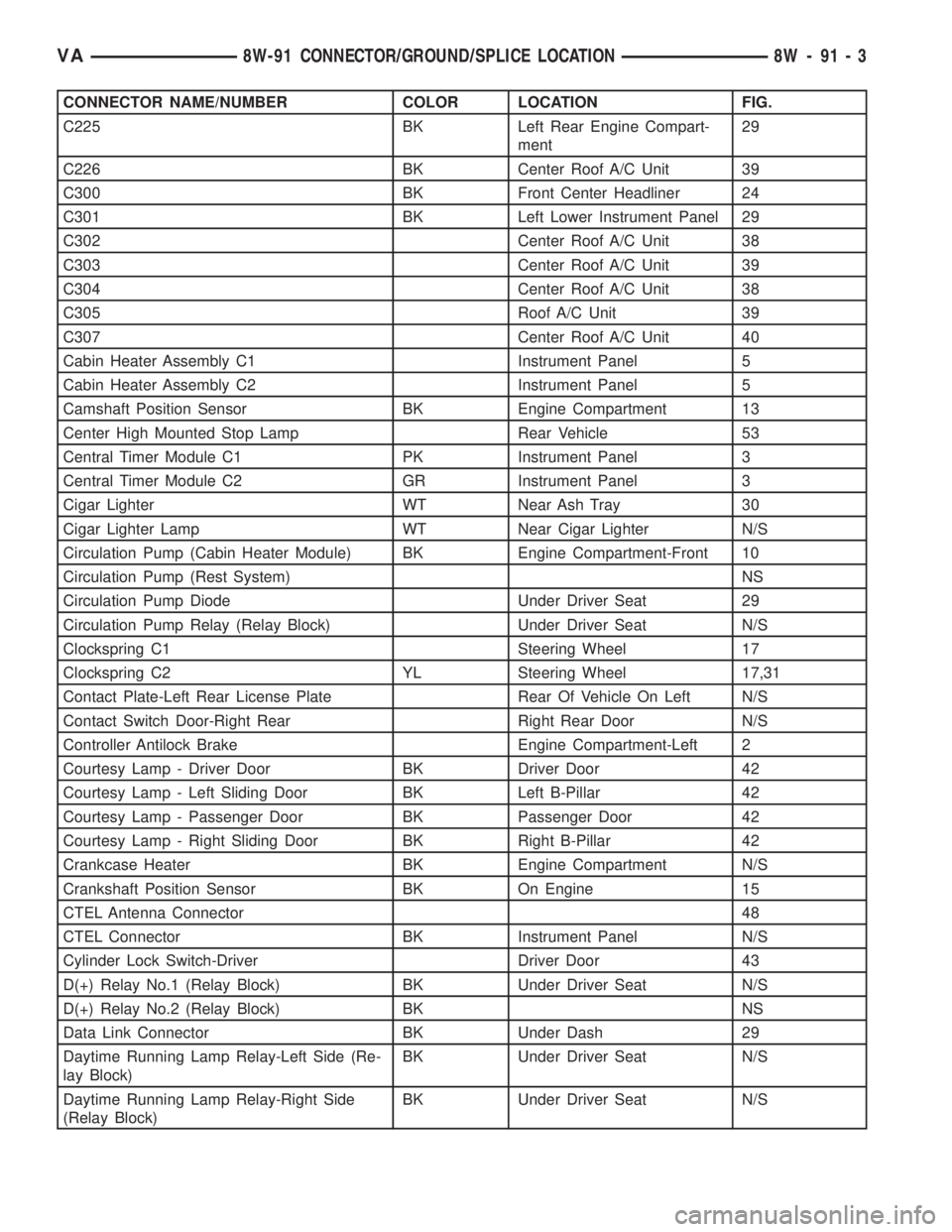
CONNECTOR NAME/NUMBER COLOR LOCATION FIG.
C225 BK Left Rear Engine Compart-
ment29
C226 BK Center Roof A/C Unit 39
C300 BK Front Center Headliner 24
C301 BK Left Lower Instrument Panel 29
C302 Center Roof A/C Unit 38
C303 Center Roof A/C Unit 39
C304 Center Roof A/C Unit 38
C305 Roof A/C Unit 39
C307 Center Roof A/C Unit 40
Cabin Heater Assembly C1 Instrument Panel 5
Cabin Heater Assembly C2 Instrument Panel 5
Camshaft Position Sensor BK Engine Compartment 13
Center High Mounted Stop Lamp Rear Vehicle 53
Central Timer Module C1 PK Instrument Panel 3
Central Timer Module C2 GR Instrument Panel 3
Cigar Lighter WT Near Ash Tray 30
Cigar Lighter Lamp WT Near Cigar Lighter N/S
Circulation Pump (Cabin Heater Module) BK Engine Compartment-Front 10
Circulation Pump (Rest System) NS
Circulation Pump Diode Under Driver Seat 29
Circulation Pump Relay (Relay Block) Under Driver Seat N/S
Clockspring C1 Steering Wheel 17
Clockspring C2 YL Steering Wheel 17,31
Contact Plate-Left Rear License Plate Rear Of Vehicle On Left N/S
Contact Switch Door-Right Rear Right Rear Door N/S
Controller Antilock Brake Engine Compartment-Left 2
Courtesy Lamp - Driver Door BK Driver Door 42
Courtesy Lamp - Left Sliding Door BK Left B-Pillar 42
Courtesy Lamp - Passenger Door BK Passenger Door 42
Courtesy Lamp - Right Sliding Door BK Right B-Pillar 42
Crankcase Heater BK Engine Compartment N/S
Crankshaft Position Sensor BK On Engine 15
CTEL Antenna Connector48
CTEL Connector BK Instrument Panel N/S
Cylinder Lock Switch-Driver Driver Door 43
D(+) Relay No.1 (Relay Block) BK Under Driver Seat N/S
D(+) Relay No.2 (Relay Block) BK NS
Data Link Connector BK Under Dash 29
Daytime Running Lamp Relay-Left Side (Re-
lay Block)BK Under Driver Seat N/S
Daytime Running Lamp Relay-Right Side
(Relay Block)BK Under Driver Seat N/S
VA8W-91 CONNECTOR/GROUND/SPLICE LOCATION 8W - 91 - 3
Page 2013 of 2305
INTERIOR
TABLE OF CONTENTS
page page
INTERIOR
CAUTION.............................70
A-PILLAR TRIM
REMOVAL.............................70
INSTALLATION.........................71
ASSIST HANDLE
REMOVAL.............................71
INSTALLATION.........................71
B-PILLAR TRIM
REMOVAL.............................71
INSTALLATION.........................72
BULKHEAD TRIM PANEL
REMOVAL.............................72
INSTALLATION.........................72
CARPETS AND FLOOR MATS
REMOVAL.............................72
INSTALLATION.........................73
COWL TRIM
REMOVAL.............................73
INSTALLATION.........................73
D-PILLAR TRIM
REMOVAL.............................73INSTALLATION.........................73
HEADLINER
REMOVAL.............................73
INSTALLATION.........................74
QUARTER TRIM PANEL
REMOVAL.............................74
INSTALLATION.........................75
REAR VIEW MIRROR
REMOVAL.............................75
INSTALLATION
INSTALLATION.......................75
INSTALLATION - REAR VIEW MIRROR
SUPPORT BRACKET...................75
STEPWELL SCUFF PADS
REMOVAL.............................75
INSTALLATION.........................76
SUN VISOR
REMOVAL.............................76
INSTALLATION.........................76
INTERIOR
CAUTION
CAUTION:: Do not attempt to remove interior trim
panels/moldings without first removing the neces-
sary adjacent panels. To avoid damaging the pan-
els, ensure that all the screws and clips are
removed before attempting to remove an interior
trim panel/molding. Trim panels are somewhat flex-
ible but can be damaged if handled improperly.
A - PILLAR TRIM
REMOVAL
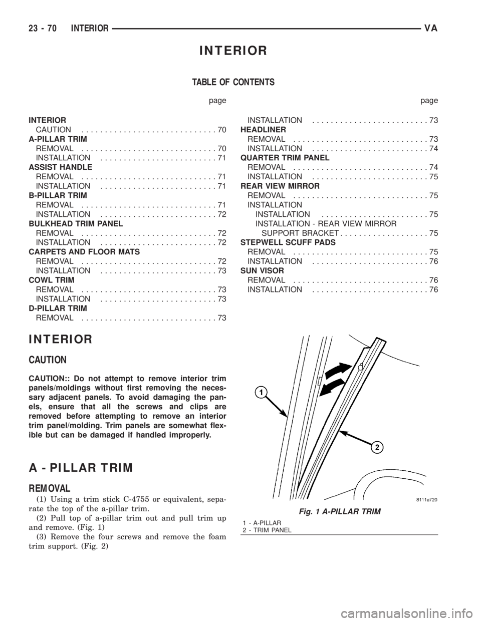
(1) Using a trim stick C-4755 or equivalent, sepa-
rate the top of the a-pillar trim.
(2) Pull top of a-pillar trim out and pull trim up
and remove. (Fig. 1)
(3) Remove the four screws and remove the foam
trim support. (Fig. 2)
Fig. 1 A-PILLAR TRIM
1 - A-PILLAR
2 - TRIM PANEL
23 - 70 INTERIORVA
Page 2014 of 2305
INSTALLATION
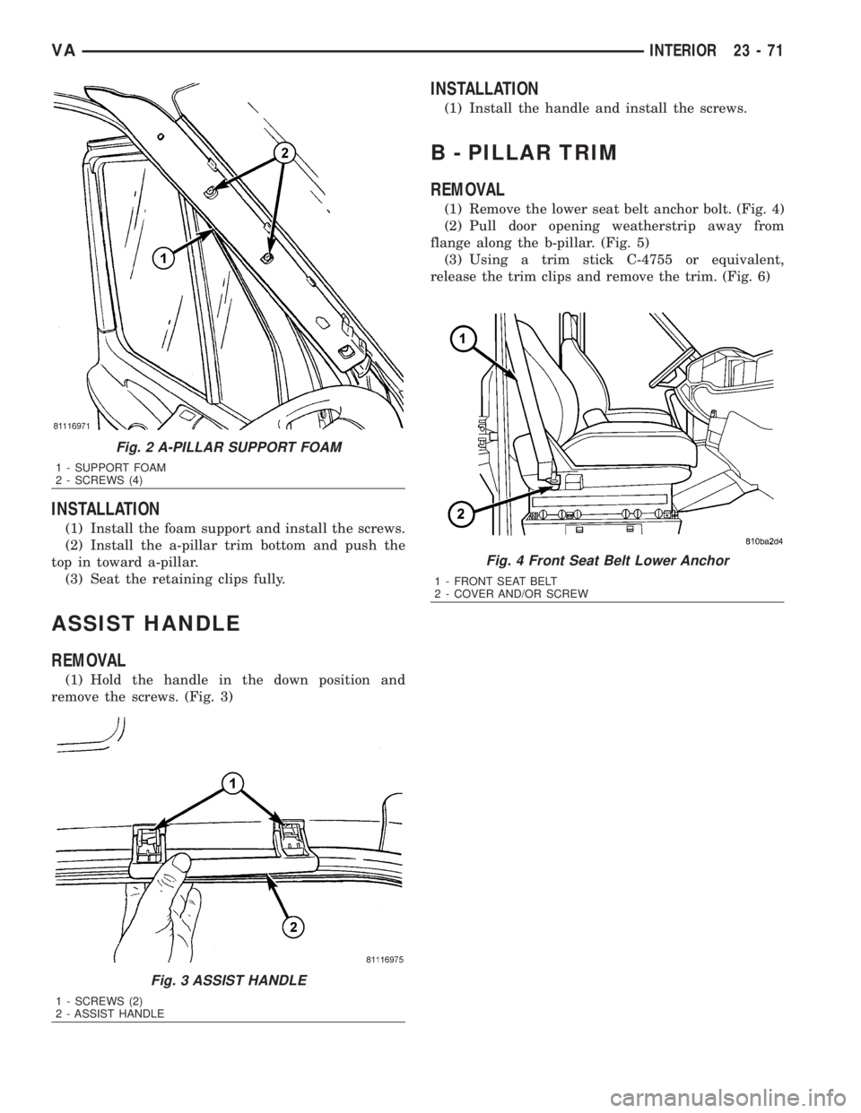
(1) Install the foam support and install the screws.
(2) Install the a-pillar trim bottom and push the
top in toward a-pillar.
(3) Seat the retaining clips fully.
ASSIST HANDLE
REMOVAL
(1) Hold the handle in the down position and
remove the screws. (Fig. 3)
INSTALLATION
(1) Install the handle and install the screws.
B - PILLAR TRIM
REMOVAL
(1) Remove the lower seat belt anchor bolt. (Fig. 4)
(2) Pull door opening weatherstrip away from
flange along the b-pillar. (Fig. 5)
(3) Using a trim stick C-4755 or equivalent,
release the trim clips and remove the trim. (Fig. 6)
Fig. 2 A-PILLAR SUPPORT FOAM
1 - SUPPORT FOAM
2 - SCREWS (4)
Fig. 3 ASSIST HANDLE
1 - SCREWS (2)
2 - ASSIST HANDLE
Fig. 4 Front Seat Belt Lower Anchor
1 - FRONT SEAT BELT
2 - COVER AND/OR SCREW
VAINTERIOR 23 - 71