2006 MERCEDES-BENZ SPRINTER torque
[x] Cancel search: torquePage 898 of 2305
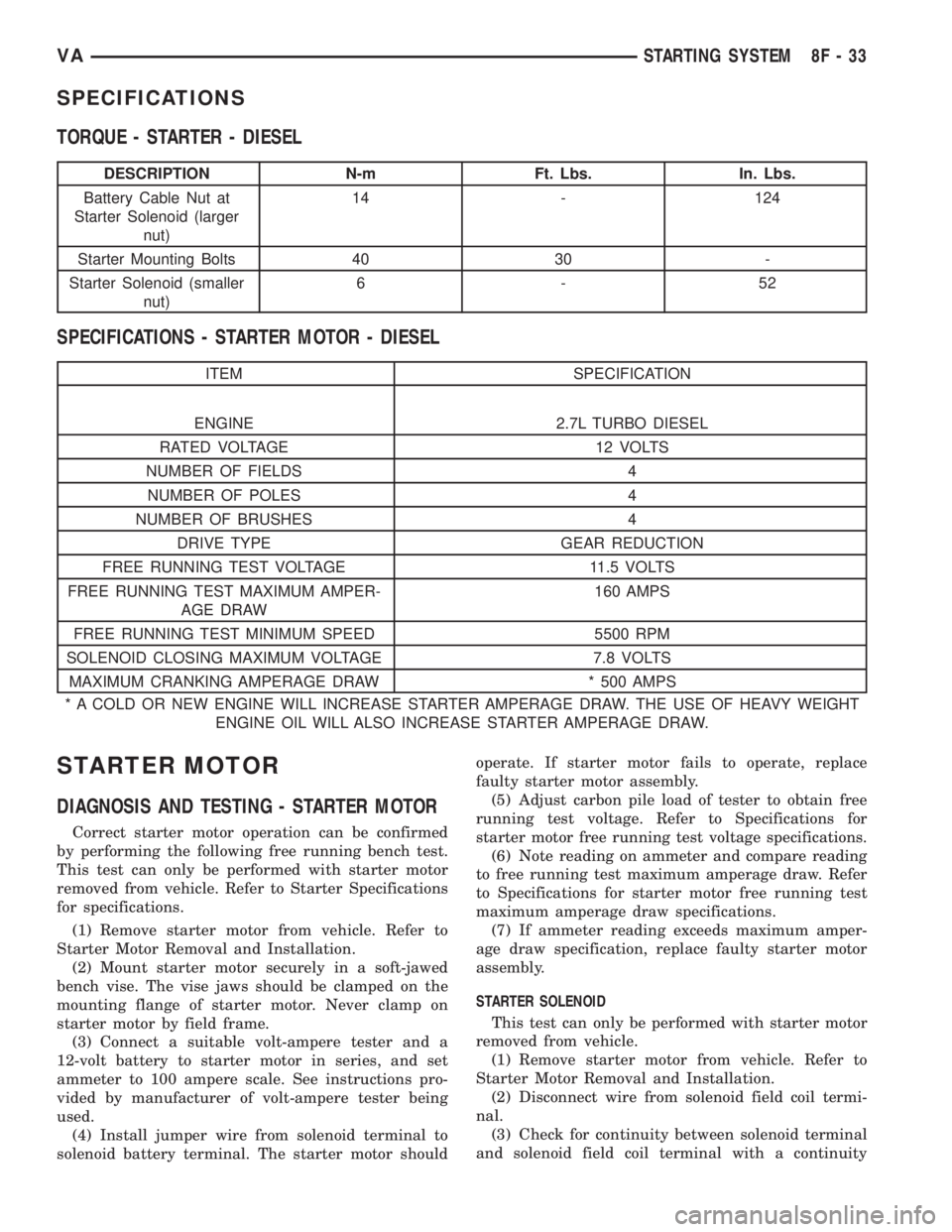
SPECIFICATIONS
TORQUE - STARTER - DIESEL
DESCRIPTION N-m Ft. Lbs. In. Lbs.
Battery Cable Nut at
Starter Solenoid (larger
nut)14 - 124
Starter Mounting Bolts 40 30 -
Starter Solenoid (smaller
nut)6-52
SPECIFICATIONS - STARTER MOTOR - DIESEL
ITEM SPECIFICATION
ENGINE 2.7L TURBO DIESEL
RATED VOLTAGE 12 VOLTS
NUMBER OF FIELDS 4
NUMBER OF POLES 4
NUMBER OF BRUSHES 4
DRIVE TYPE GEAR REDUCTION
FREE RUNNING TEST VOLTAGE 11.5 VOLTS
FREE RUNNING TEST MAXIMUM AMPER-
AGE DRAW160 AMPS
FREE RUNNING TEST MINIMUM SPEED 5500 RPM
SOLENOID CLOSING MAXIMUM VOLTAGE 7.8 VOLTS
MAXIMUM CRANKING AMPERAGE DRAW * 500 AMPS
* A COLD OR NEW ENGINE WILL INCREASE STARTER AMPERAGE DRAW. THE USE OF HEAVY WEIGHT
ENGINE OIL WILL ALSO INCREASE STARTER AMPERAGE DRAW.
STARTER MOTOR
DIAGNOSIS AND TESTING - STARTER MOTOR
Correct starter motor operation can be confirmed
by performing the following free running bench test.
This test can only be performed with starter motor
removed from vehicle. Refer to Starter Specifications
for specifications.
(1) Remove starter motor from vehicle. Refer to
Starter Motor Removal and Installation.
(2) Mount starter motor securely in a soft-jawed
bench vise. The vise jaws should be clamped on the
mounting flange of starter motor. Never clamp on
starter motor by field frame.
(3) Connect a suitable volt-ampere tester and a
12-volt battery to starter motor in series, and set
ammeter to 100 ampere scale. See instructions pro-
vided by manufacturer of volt-ampere tester being
used.
(4) Install jumper wire from solenoid terminal to
solenoid battery terminal. The starter motor shouldoperate. If starter motor fails to operate, replace
faulty starter motor assembly.
(5) Adjust carbon pile load of tester to obtain free
running test voltage. Refer to Specifications for
starter motor free running test voltage specifications.
(6) Note reading on ammeter and compare reading
to free running test maximum amperage draw. Refer
to Specifications for starter motor free running test
maximum amperage draw specifications.
(7) If ammeter reading exceeds maximum amper-
age draw specification, replace faulty starter motor
assembly.
STARTER SOLENOID
This test can only be performed with starter motor
removed from vehicle.
(1) Remove starter motor from vehicle. Refer to
Starter Motor Removal and Installation.
(2) Disconnect wire from solenoid field coil termi-
nal.
(3) Check for continuity between solenoid terminal
and solenoid field coil terminal with a continuity
VASTARTING SYSTEM 8F - 33
Page 900 of 2305
INSTALLATION
(1) Raise and support vehicle.
(2) Position starter motor to transmission housing.
(3) Install 2 mounting bolts. Refer to Torque Spec-
ifications.
(4) Lower vehicle.
(5) Connect battery cable and solenoid wiring to
solenoid (2 nuts). Refer to Torque Specifications.
(6) Position wiring harness trough and install
retaining bolt.
(7) Install new nylon tie-wraps to wiring trough.
(8) Connect negative battery cable.
STARTER MOTOR RELAY
DESCRIPTION
The starter relay is an electromechanical device
that switches battery current to the pull-in coil of the
starter solenoid when ignition switch is turned to
Start position. The starter relay is located in the
Fuse/Relay Block. The Fuse/Relay Block is located
under, and to the left side of the drivers seat. See
Fuse/Relay Block cover for relay identification and
location.
The starter relay is an International Standards
Organization (ISO) relay. Relays conforming to ISO
specifications have common physical dimensions, cur-rent capacities, terminal patterns, and terminal func-
tions.
The starter relay cannot be repaired or adjusted
and, if faulty or damaged, it must be replaced.
REMOVAL
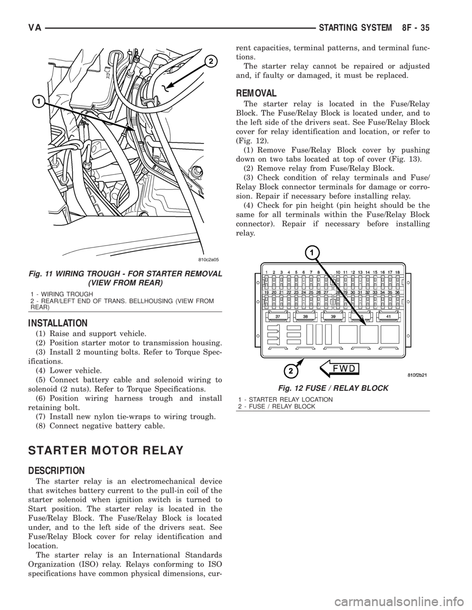
The starter relay is located in the Fuse/Relay
Block. The Fuse/Relay Block is located under, and to
the left side of the drivers seat. See Fuse/Relay Block
cover for relay identification and location, or refer to
(Fig. 12).
(1) Remove Fuse/Relay Block cover by pushing
down on two tabs located at top of cover (Fig. 13).
(2) Remove relay from Fuse/Relay Block.
(3) Check condition of relay terminals and Fuse/
Relay Block connector terminals for damage or corro-
sion. Repair if necessary before installing relay.
(4) Check for pin height (pin height should be the
same for all terminals within the Fuse/Relay Block
connector). Repair if necessary before installing
relay.
Fig. 11 WIRING TROUGH - FOR STARTER REMOVAL
(VIEW FROM REAR)
1 - WIRING TROUGH
2 - REAR/LEFT END OF TRANS. BELLHOUSING (VIEW FROM
REAR)
Fig. 12 FUSE / RELAY BLOCK
1 - STARTER RELAY LOCATION
2 - FUSE / RELAY BLOCK
VASTARTING SYSTEM 8F - 35
Page 1005 of 2305
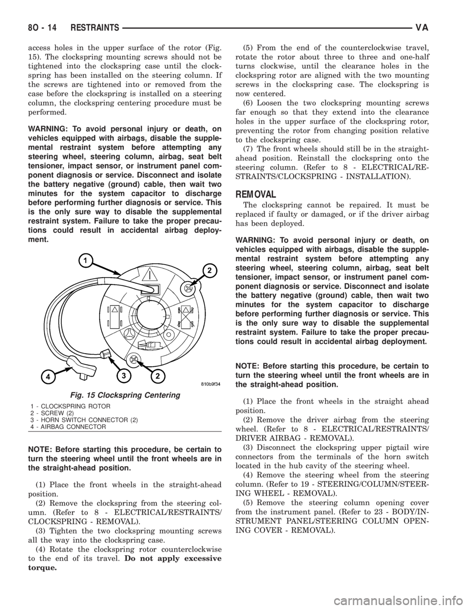
access holes in the upper surface of the rotor (Fig.
15). The clockspring mounting screws should not be
tightened into the clockspring case until the clock-
spring has been installed on the steering column. If
the screws are tightened into or removed from the
case before the clockspring is installed on a steering
column, the clockspring centering procedure must be
performed.
WARNING: To avoid personal injury or death, on
vehicles equipped with airbags, disable the supple-
mental restraint system before attempting any
steering wheel, steering column, airbag, seat belt
tensioner, impact sensor, or instrument panel com-
ponent diagnosis or service. Disconnect and isolate
the battery negative (ground) cable, then wait two
minutes for the system capacitor to discharge
before performing further diagnosis or service. This
is the only sure way to disable the supplemental
restraint system. Failure to take the proper precau-
tions could result in accidental airbag deploy-
ment.
NOTE: Before starting this procedure, be certain to
turn the steering wheel until the front wheels are in
the straight-ahead position.
(1) Place the front wheels in the straight-ahead
position.
(2) Remove the clockspring from the steering col-
umn. (Refer to 8 - ELECTRICAL/RESTRAINTS/
CLOCKSPRING - REMOVAL).
(3) Tighten the two clockspring mounting screws
all the way into the clockspring case.
(4) Rotate the clockspring rotor counterclockwise
to the end of its travel.Do not apply excessive
torque.(5) From the end of the counterclockwise travel,
rotate the rotor about three to three and one-half
turns clockwise, until the clearance holes in the
clockspring rotor are aligned with the two mounting
screws in the clockspring case. The clockspring is
now centered.
(6) Loosen the two clockspring mounting screws
far enough so that they extend into the clearance
holes in the upper surface of the clockspring rotor,
preventing the rotor from changing position relative
to the clockspring case.
(7) The front wheels should still be in the straight-
ahead position. Reinstall the clockspring onto the
steering column. (Refer to 8 - ELECTRICAL/RE-
STRAINTS/CLOCKSPRING - INSTALLATION).
REMOVAL
The clockspring cannot be repaired. It must be
replaced if faulty or damaged, or if the driver airbag
has been deployed.
WARNING: To avoid personal injury or death, on
vehicles equipped with airbags, disable the supple-
mental restraint system before attempting any
steering wheel, steering column, airbag, seat belt
tensioner, impact sensor, or instrument panel com-
ponent diagnosis or service. Disconnect and isolate
the battery negative (ground) cable, then wait two
minutes for the system capacitor to discharge
before performing further diagnosis or service. This
is the only sure way to disable the supplemental
restraint system. Failure to take the proper precau-
tions could result in accidental airbag deployment.
NOTE: Before starting this procedure, be certain to
turn the steering wheel until the front wheels are in
the straight-ahead position.
(1) Place the front wheels in the straight ahead
position.
(2) Remove the driver airbag from the steering
wheel. (Refer to 8 - ELECTRICAL/RESTRAINTS/
DRIVER AIRBAG - REMOVAL).
(3) Disconnect the clockspring upper pigtail wire
connectors from the terminals of the horn switch
located in the hub cavity of the steering wheel.
(4) Remove the steering wheel from the steering
column. (Refer to 19 - STEERING/COLUMN/STEER-
ING WHEEL - REMOVAL).
(5) Remove the steering column opening cover
from the instrument panel. (Refer to 23 - BODY/IN-
STRUMENT PANEL/STEERING COLUMN OPEN-
ING COVER - REMOVAL).
Fig. 15 Clockspring Centering
1 - CLOCKSPRING ROTOR
2 - SCREW (2)
3 - HORN SWITCH CONNECTOR (2)
4 - AIRBAG CONNECTOR
8O - 14 RESTRAINTSVA
Page 1034 of 2305
SPEED CONTROL
TABLE OF CONTENTS
page page
SPEED CONTROL
DESCRIPTION..........................1
OPERATION............................2
SPECIFICATIONS
TORQUE.............................2
CABLE
DESCRIPTION..........................2SERVO
DESCRIPTION..........................2
SWITCH
REMOVAL.............................3
INSTALLATION..........................3
SPEED CONTROL
DESCRIPTION
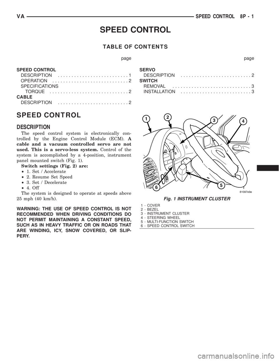
The speed control system is electronically con-
trolled by the Engine Control Module (ECM).A
cable and a vacuum controlled servo are not
used. This is a servo-less system.Control of the
system is accomplished by a 4-position, instrument
panel mounted switch (Fig. 1).
Switch settings (Fig. 2) are:
²1. Set / Accelerate
²2. Resume Set Speed
²3. Set / Decelerate
²4. Off
The system is designed to operate at speeds above
25 mph (40 km/h).
WARNING: THE USE OF SPEED CONTROL IS NOT
RECOMMENDED WHEN DRIVING CONDITIONS DO
NOT PERMIT MAINTAINING A CONSTANT SPEED,
SUCH AS IN HEAVY TRAFFIC OR ON ROADS THAT
ARE WINDING, ICY, SNOW COVERED, OR SLIP-
PERY.
Fig. 1 INSTRUMENT CLUSTER
1 - COVER
2 - BEZEL
3 - INSTRUMENT CLUSTER
4 - STEERING WHEEL
5 - MULTI-FUNCTION SWITCH
6 - SPEED CONTROL SWITCH
VASPEED CONTROL 8P - 1
Page 1035 of 2305
OPERATION
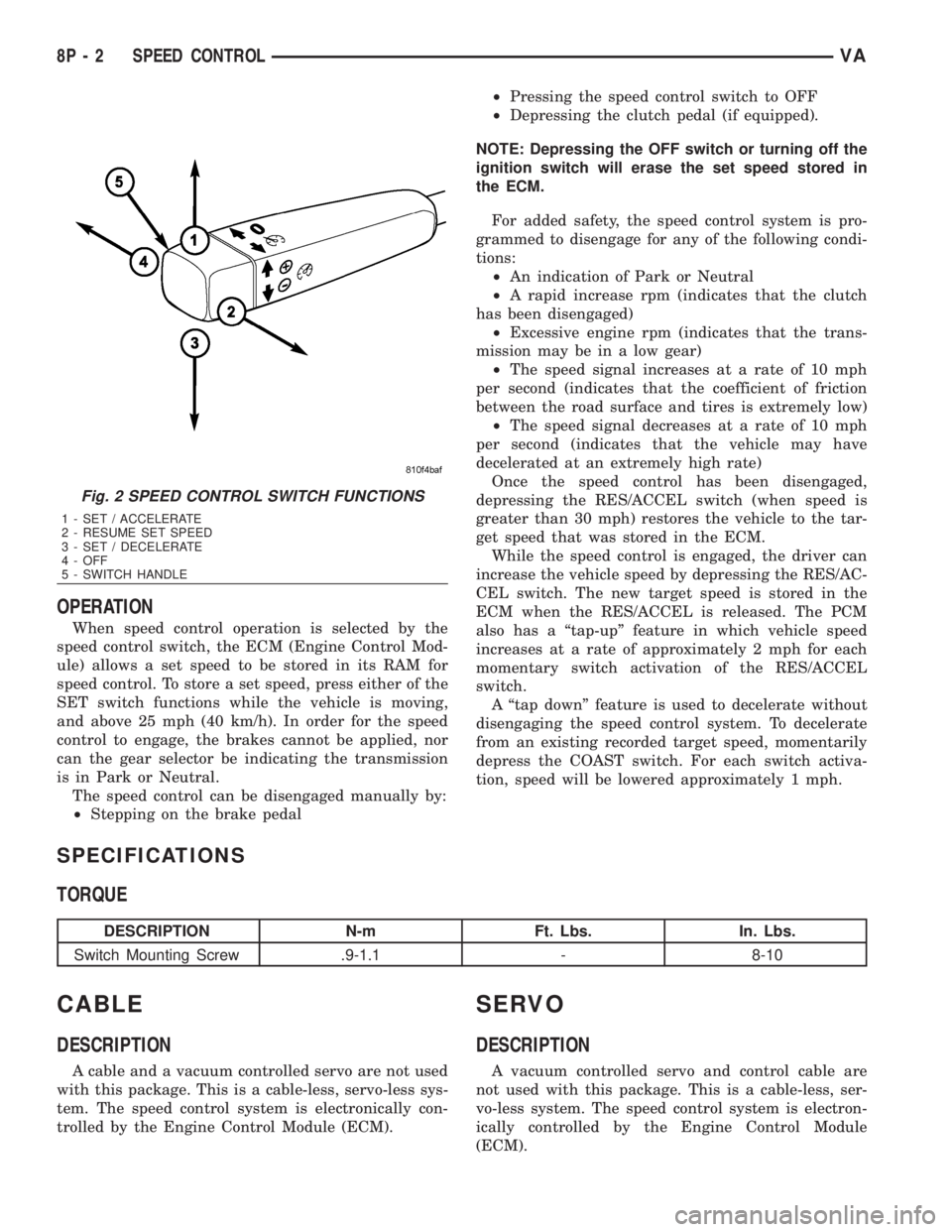
When speed control operation is selected by the
speed control switch, the ECM (Engine Control Mod-
ule) allows a set speed to be stored in its RAM for
speed control. To store a set speed, press either of the
SET switch functions while the vehicle is moving,
and above 25 mph (40 km/h). In order for the speed
control to engage, the brakes cannot be applied, nor
can the gear selector be indicating the transmission
is in Park or Neutral.
The speed control can be disengaged manually by:
²Stepping on the brake pedal²Pressing the speed control switch to OFF
²Depressing the clutch pedal (if equipped).
NOTE: Depressing the OFF switch or turning off the
ignition switch will erase the set speed stored in
the ECM.
For added safety, the speed control system is pro-
grammed to disengage for any of the following condi-
tions:
²An indication of Park or Neutral
²A rapid increase rpm (indicates that the clutch
has been disengaged)
²Excessive engine rpm (indicates that the trans-
mission may be in a low gear)
²The speed signal increases at a rate of 10 mph
per second (indicates that the coefficient of friction
between the road surface and tires is extremely low)
²The speed signal decreases at a rate of 10 mph
per second (indicates that the vehicle may have
decelerated at an extremely high rate)
Once the speed control has been disengaged,
depressing the RES/ACCEL switch (when speed is
greater than 30 mph) restores the vehicle to the tar-
get speed that was stored in the ECM.
While the speed control is engaged, the driver can
increase the vehicle speed by depressing the RES/AC-
CEL switch. The new target speed is stored in the
ECM when the RES/ACCEL is released. The PCM
also has a ªtap-upº feature in which vehicle speed
increases at a rate of approximately 2 mph for each
momentary switch activation of the RES/ACCEL
switch.
A ªtap downº feature is used to decelerate without
disengaging the speed control system. To decelerate
from an existing recorded target speed, momentarily
depress the COAST switch. For each switch activa-
tion, speed will be lowered approximately 1 mph.
SPECIFICATIONS
TORQUE
DESCRIPTION N-m Ft. Lbs. In. Lbs.
Switch Mounting Screw .9-1.1 - 8-10
CABLE
DESCRIPTION
A cable and a vacuum controlled servo are not used
with this package. This is a cable-less, servo-less sys-
tem. The speed control system is electronically con-
trolled by the Engine Control Module (ECM).
SERVO
DESCRIPTION
A vacuum controlled servo and control cable are
not used with this package. This is a cable-less, ser-
vo-less system. The speed control system is electron-
ically controlled by the Engine Control Module
(ECM).
Fig. 2 SPEED CONTROL SWITCH FUNCTIONS
1 - SET / ACCELERATE
2 - RESUME SET SPEED
3 - SET / DECELERATE
4 - OFF
5 - SWITCH HANDLE
8P - 2 SPEED CONTROLVA
Page 1036 of 2305
SWITCH
REMOVAL
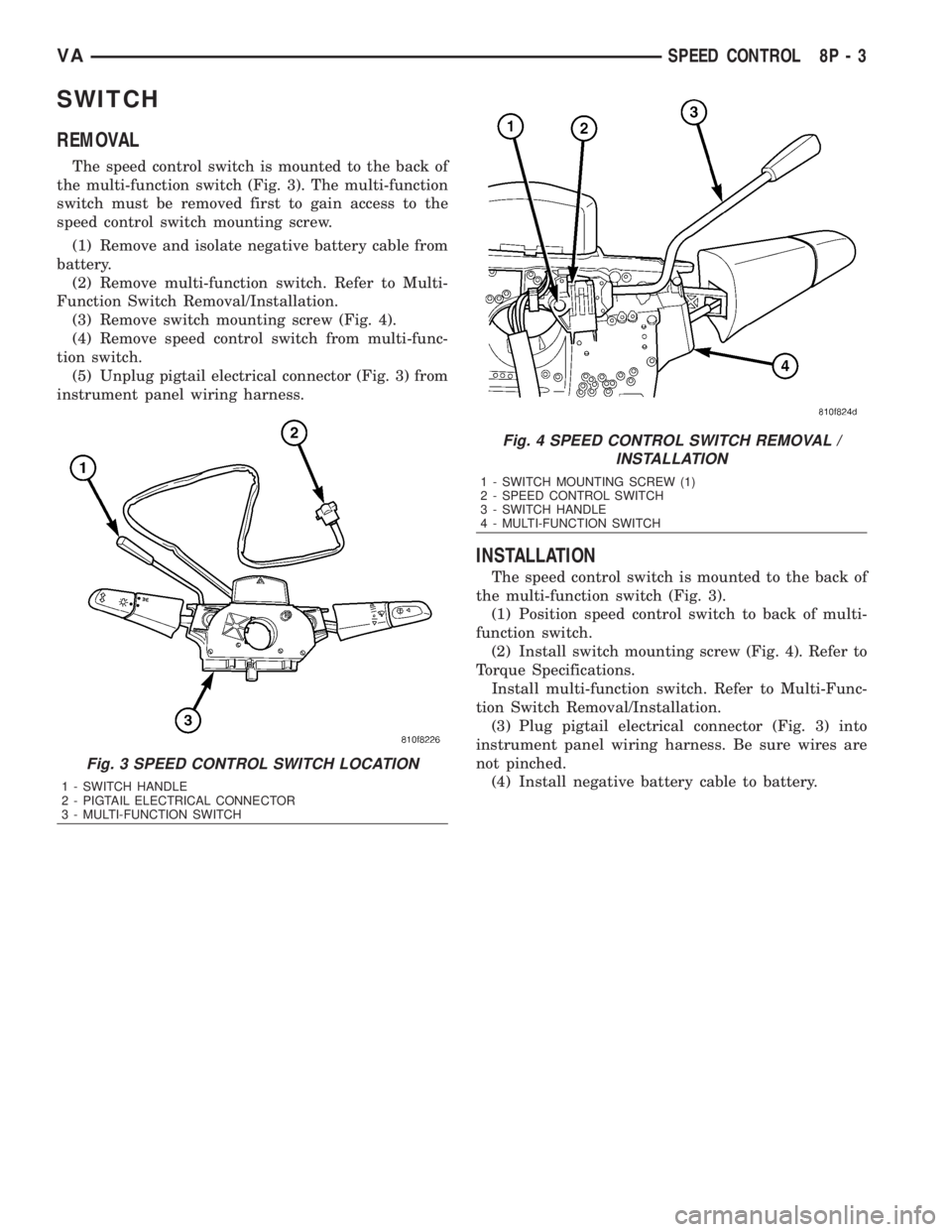
The speed control switch is mounted to the back of
the multi-function switch (Fig. 3). The multi-function
switch must be removed first to gain access to the
speed control switch mounting screw.
(1) Remove and isolate negative battery cable from
battery.
(2) Remove multi-function switch. Refer to Multi-
Function Switch Removal/Installation.
(3) Remove switch mounting screw (Fig. 4).
(4) Remove speed control switch from multi-func-
tion switch.
(5) Unplug pigtail electrical connector (Fig. 3) from
instrument panel wiring harness.
INSTALLATION
The speed control switch is mounted to the back of
the multi-function switch (Fig. 3).
(1) Position speed control switch to back of multi-
function switch.
(2) Install switch mounting screw (Fig. 4). Refer to
Torque Specifications.
Install multi-function switch. Refer to Multi-Func-
tion Switch Removal/Installation.
(3) Plug pigtail electrical connector (Fig. 3) into
instrument panel wiring harness. Be sure wires are
not pinched.
(4) Install negative battery cable to battery.
Fig. 3 SPEED CONTROL SWITCH LOCATION
1 - SWITCH HANDLE
2 - PIGTAIL ELECTRICAL CONNECTOR
3 - MULTI-FUNCTION SWITCH
Fig. 4 SPEED CONTROL SWITCH REMOVAL /
INSTALLATION
1 - SWITCH MOUNTING SCREW (1)
2 - SPEED CONTROL SWITCH
3 - SWITCH HANDLE
4 - MULTI-FUNCTION SWITCH
VASPEED CONTROL 8P - 3
Page 1576 of 2305
ENGINE
TABLE OF CONTENTS
page page
ENGINE
DESCRIPTION..........................2
STANDARD PROCEDURE
STANDARD PROCEDURE - COMPRESSION
TESTING ENGINE......................3
STANDARD PROCEDURE - CYLINDER
LEAK DOWN TEST.....................3
STANDARD PROCEDURE - DETERMINING
CYLINDER PRESSURE LOSS.............4
REMOVAL
REMOVAL - ENGINE COVER.............4
REMOVAL............................5
INSTALLATION
INSTALLATION - ENGINE COVER..........9
INSTALLATION........................9
SPECIFICATIONS - TORQUE
SPECIFICATIONS.....................11
SPECIAL TOOLS.......................17
AIR CLEANER ELEMENT
REMOVAL.............................21
INSTALLATION.........................21
AIR CLEANER HOUSING
REMOVAL.............................21
INSTALLATION.........................22
CYLINDER HEAD
DESCRIPTION.........................22
STANDARD PROCEDURE
STANDARD PROCEDURE - CYLINDER
HEAD BOLT INSPECTION...............22
STANDARD PROCEDURE - MEASURE
CYLINDER HEAD SURFACE.............22
REMOVAL
REMOVAL - CYLINDER HEAD............23
REMOVAL - CYLINDER HEAD FRONT
COVER.............................25
REMOVAL - CYLINDER HEAD GUIDE RAIL . . 26
INSTALLATION
INSTALLATION - CYLINDER HEAD........26
INSTALLATION - CYLINDER HEAD FRONT
COVER.............................28
INSTALLATION - CYLINDER HEAD GUIDE
RAIL...............................28
CAMSHAFT(S)
STANDARD PROCEDURE
STANDARD PROCEDURE - CHECKING
CAMSHAFT POSITION.................28
STANDARD PROCEDURE - INSPECTING
TAPPET CLEARANCE..................30
REMOVAL.............................30
INSTALLATION.........................32CYLINDER HEAD COVER(S)
REMOVAL.............................33
INSTALLATION.........................34
VALVE STEM SEALS
DESCRIPTION.........................34
VALVE SPRINGS
REMOVAL
REMOVAL - VALVE SPRINGS............35
REMOVAL - VALVES...................36
INSTALLATION
INSTALLATION - VALVE SPRINGS........36
INSTALLATION - VALVES...............37
ENGINE BLOCK
STANDARD PROCEDURE
STANDARD PROCEDURE - REPLACING
ENGINE CORE AND OIL GALLERY PLUGS . . 37
STANDARD PROCEDURE - MEASURING
CYLINDER BORES....................38
CRANKSHAFT
DESCRIPTION.........................39
STANDARD PROCEDURE - MEASURE
CRANKSHAFT AND BLOCK JOURNALS....39
REMOVAL.............................40
INSTALLATION.........................40
CRANKSHAFT OIL SEAL - REAR
REMOVAL.............................41
INSTALLATION.........................42
CRANKSHAFT OIL SEAL - FRONT
REMOVAL.............................42
INSTALLATION.........................43
FLYWHEEL
REMOVAL.............................43
INSTALLATION
INSTALLATION.......................44
INSTALLATION - CRANKSHAFT LOCK.....44
PISTON & CONNECTING ROD
DESCRIPTION.........................45
STANDARD PROCEDURE
STANDARD PROCEDURE - CHECKING AND
REPAIRING CONNECTING RODS.........46
STANDARD PROCEDURE - MEASURING
PISTON PROTRUSION.................47
REMOVAL.............................47
INSTALLATION.........................49
PISTON RINGS
STANDARD PROCEDURE - PISTON RING
FITTING.............................52
VIBRATION DAMPER
REMOVAL.............................53
INSTALLATION.........................54
VAENGINE 9 - 1
Page 1578 of 2305
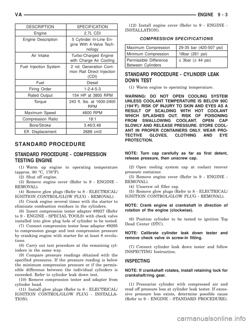
DESCRIPTION SPECIFICATION
Engine 2.7L CDI
Engine Description 5 Cylinder In-Line En-
gine With 4-Valve Tech-
nology
Air Intake Turbo-Charged Engine
with Charge Air Cooling
Fuel Injection System 2 nd. Generation Com-
mon Rail Direct Injection
(CDI)
Fuel Diesel
Firing Order 1-2-4-5-3
Rated Output 154 HP at 3800 RPM
Torque 243 ft. lbs. at 1600-2400
RPM
Maximum Speed 4800 RPM
Compression Ratio 18:1
Bore/Stroke 3.46/3.48
Eff. Displacement 2688 cm3
STANDARD PROCEDURE
STANDARD PROCEDURE - COMPRESSION
TESTING ENGINE
(1) Warm up engine to operating temperature
(approx. 80 ÉC, 176ÉF).
(2) Shut off engine.
(3) Remove engine cover (Refer to 9 - ENGINE -
REMOVAL).
(4) Remove glow plugs (Refer to 8 - ELECTRICAL/
IGNITION CONTROL/GLOW PLUG - REMOVAL).
(5) Crank engine several times with the starter to
eliminate combustion residues in the cylinders.
(6) Insert compression tester adapter #8927 (Refer
to 9 - ENGINE - SPECIAL TOOLS) with check valve
installed into glow plug hole of cylinder to be tested.
(7) Connect compression tester hose adapter #9295
to compression gauge and test compression pressure
by cranking engine with starter for at least 8 revolu-
tions.
(8) Carry out test procedure at the remaining cyl-
inders in the same way.
(9) Compare pressure readings obtained with the
specified pressures. If the pressure reading is below
the minimum compression pressure or if the permis-
sible difference between the individual cylinders is
exceeded. Refer to cylinder leak down test.
(10) Remove compression tester and adapter from
cylinder head.
(11) Install glow plugs (Refer to 8 - ELECTRICAL/
IGNITION CONTROL/GLOW PLUG - INSTALLA-
TION).(12) Install engine cover (Refer to 9 - ENGINE -
INSTALLATION).
COMPRESSION SPECIFICATIONS
Maximum Compression 29-35 bar (420-507 psi)
Minimum Compression 18bar (261 psi)
Permissible Difference
Between Cylinders 3bar ( 44 psi)
STANDARD PROCEDURE - CYLINDER LEAK
DOWN TEST
(1) Warm engine to operating temperature.
WARNING: DO NOT OPEN COOLING SYSTEM
UNLESS COOLANT TEMPERATURE IS BELOW 90C
(194ÉF). RISK OF INJURY TO SKIN AND EYES AS A
RESULT OF SCALDING WITH HOT COOLANT
WHICH SPLASHES OUT. RISK OF POISONING
FROM SWALLOWING COOLANT. OPEN CAP
SLOWLY AND RELEASE PRESSURE. STORE COOL-
ANT IN PROPER CONTAINERS ONLY. WEAR PRO-
TECTIVE GLOVES, CLOTHING AND EYE
PROTECTION.
NOTE: Turn cap carefully as far as first detent,
release pressure, then unscrew cap.
(2) Open cooling system cap at coolant recover
pressure container.
(3) Remove engine cover (Refer to 9 - ENGINE -
REMOVAL).
(4) Unscrew oil filler cap.
(5) Remove glow plugs (Refer to 8 - ELECTRICAL/
IGNITION CONTROL/GLOW PLUG - REMOVAL).
NOTE: Crank engine at crankshaft in direction of
rotation of the engine (clockwise).
(6) Position cylinder to be tested to ignition Top
Dead Center (DTC).
NOTE: Calibrate cylinder leak down tester and
remove check valve in screw-in fitting.
(7) Connect cylinder leak down tester and follow
INSPECTING Instruction.
INSPECTING
NOTE: If crankshaft rotates, install retaining lock for
crankshaft/ring gear.
(1) Pressurize cylinder with compressed air and
read off pressure loss at cylinder leak tester. If exces-
sive pressure loss exists, determine possible cause
(Refer to 9 - ENGINE - STANDARD PROCEDURE).
VAENGINE 9 - 3