2006 MERCEDES-BENZ SPRINTER torque
[x] Cancel search: torquePage 2173 of 2305
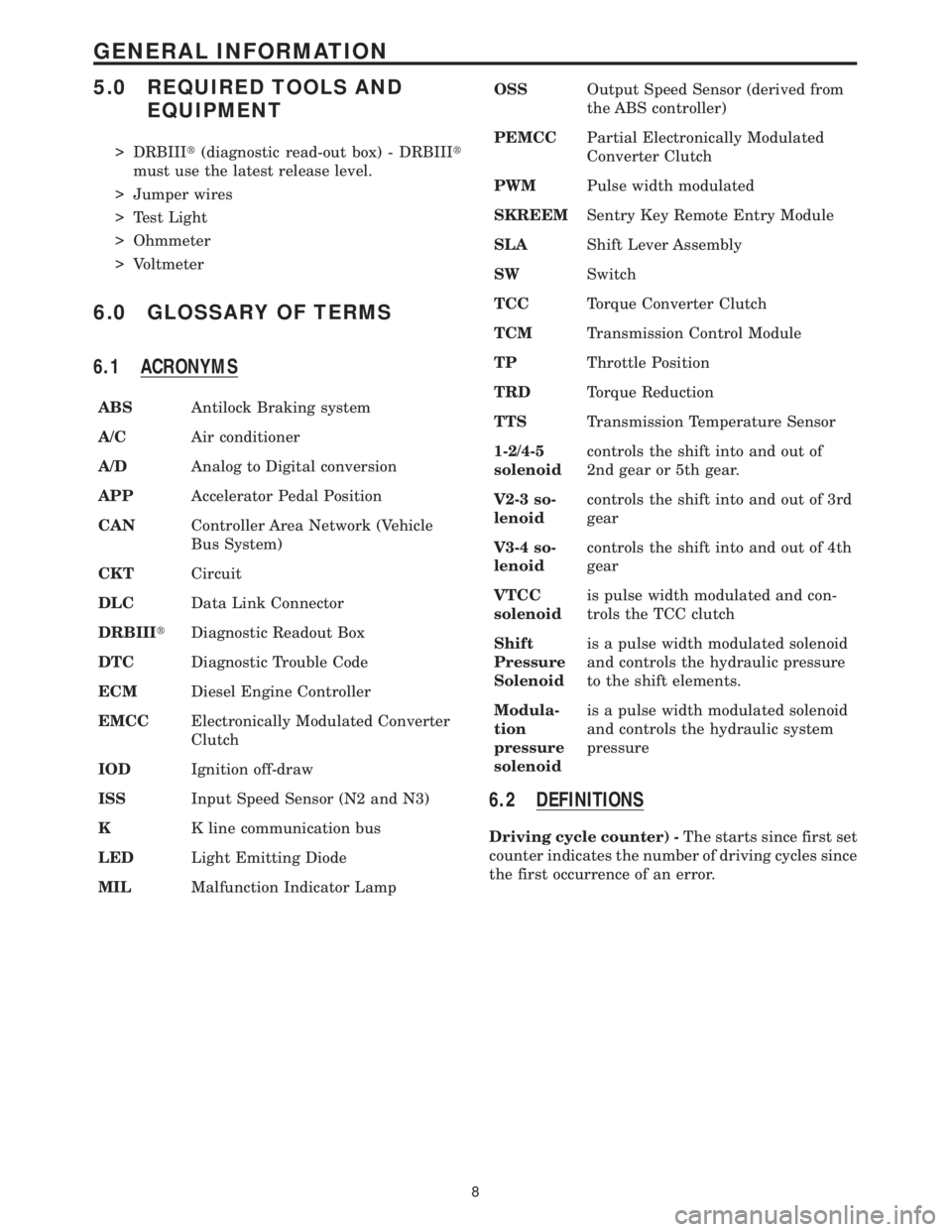
5.0 REQUIRED TOOLS AND
EQUIPMENT
> DRBIIIt(diagnostic read-out box) - DRBIIIt
must use the latest release level.
> Jumper wires
> Test Light
> Ohmmeter
> Voltmeter
6.0 GLOSSARY OF TERMS
6.1 ACRONYMS
ABSAntilock Braking system
A/CAir conditioner
A/DAnalog to Digital conversion
APPAccelerator Pedal Position
CANController Area Network (Vehicle
Bus System)
CKTCircuit
DLCData Link Connector
DRBIIItDiagnostic Readout Box
DTCDiagnostic Trouble Code
ECMDiesel Engine Controller
EMCCElectronically Modulated Converter
Clutch
IODIgnition off-draw
ISSInput Speed Sensor (N2 and N3)
KK line communication bus
LEDLight Emitting Diode
MILMalfunction Indicator LampOSSOutput Speed Sensor (derived from
the ABS controller)
PEMCCPartial Electronically Modulated
Converter Clutch
PWMPulse width modulated
SKREEMSentry Key Remote Entry Module
SLAShift Lever Assembly
SWSwitch
TCCTorque Converter Clutch
TCMTransmission Control Module
TPThrottle Position
TRDTorque Reduction
TTSTransmission Temperature Sensor
1-2/4-5
solenoidcontrols the shift into and out of
2nd gear or 5th gear.
V2-3 so-
lenoidcontrols the shift into and out of 3rd
gear
V3-4 so-
lenoidcontrols the shift into and out of 4th
gear
VTCC
solenoidis pulse width modulated and con-
trols the TCC clutch
Shift
Pressure
Solenoidis a pulse width modulated solenoid
and controls the hydraulic pressure
to the shift elements.
Modula-
tion
pressure
solenoidis a pulse width modulated solenoid
and controls the hydraulic system
pressure
6.2 DEFINITIONS
Driving cycle counter) -The starts since first set
counter indicates the number of driving cycles since
the first occurrence of an error.
8
GENERAL INFORMATION
Page 2231 of 2305
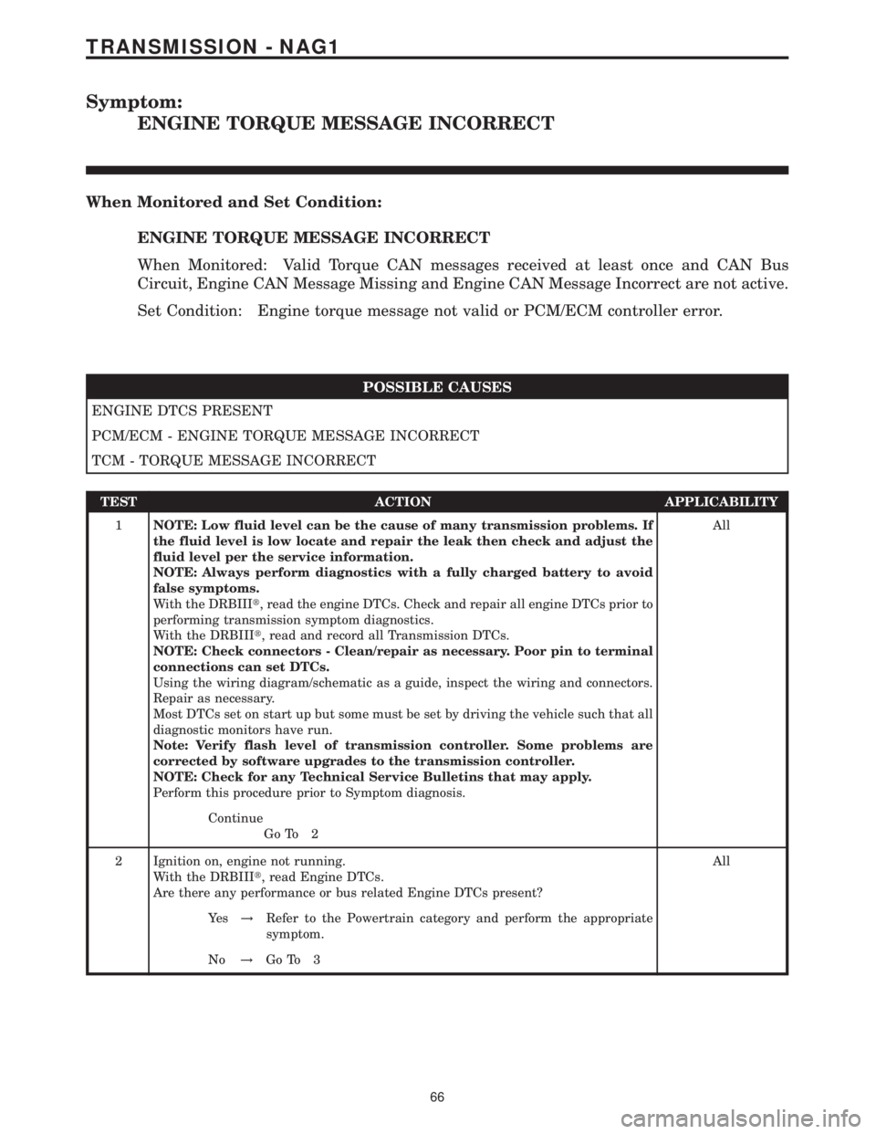
Symptom:
ENGINE TORQUE MESSAGE INCORRECT
When Monitored and Set Condition:
ENGINE TORQUE MESSAGE INCORRECT
When Monitored: Valid Torque CAN messages received at least once and CAN Bus
Circuit, Engine CAN Message Missing and Engine CAN Message Incorrect are not active.
Set Condition: Engine torque message not valid or PCM/ECM controller error.
POSSIBLE CAUSES
ENGINE DTCS PRESENT
PCM/ECM - ENGINE TORQUE MESSAGE INCORRECT
TCM - TORQUE MESSAGE INCORRECT
TEST ACTION APPLICABILITY
1NOTE: Low fluid level can be the cause of many transmission problems. If
the fluid level is low locate and repair the leak then check and adjust the
fluid level per the service information.
NOTE: Always perform diagnostics with a fully charged battery to avoid
false symptoms.
With the DRBIIIt, read the engine DTCs. Check and repair all engine DTCs prior to
performing transmission symptom diagnostics.
With the DRBIIIt, read and record all Transmission DTCs.
NOTE: Check connectors - Clean/repair as necessary. Poor pin to terminal
connections can set DTCs.
Using the wiring diagram/schematic as a guide, inspect the wiring and connectors.
Repair as necessary.
Most DTCs set on start up but some must be set by driving the vehicle such that all
diagnostic monitors have run.
Note: Verify flash level of transmission controller. Some problems are
corrected by software upgrades to the transmission controller.
NOTE: Check for any Technical Service Bulletins that may apply.
Perform this procedure prior to Symptom diagnosis.All
Continue
Go To 2
2 Ignition on, engine not running.
With the DRBIIIt, read Engine DTCs.
Are there any performance or bus related Engine DTCs present?All
Ye s!Refer to the Powertrain category and perform the appropriate
symptom.
No!Go To 3
66
TRANSMISSION - NAG1
Page 2232 of 2305
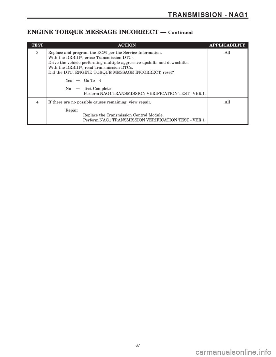
TEST ACTION APPLICABILITY
3 Replace and program the ECM per the Service Information.
With the DRBIIIt, erase Transmission DTCs.
Drive the vehicle performing multiple aggressive upshifts and downshifts.
With the DRBIIIt, read Transmission DTCs.
Did the DTC, ENGINE TORQUE MESSAGE INCORRECT, reset?All
Ye s!Go To 4
No!Test Complete
Perform NAG1 TRANSMISSION VERIFICATION TEST - VER 1.
4 If there are no possible causes remaining, view repair. All
Repair
Replace the Transmission Control Module.
Perform NAG1 TRANSMISSION VERIFICATION TEST - VER 1.
67
TRANSMISSION - NAG1
ENGINE TORQUE MESSAGE INCORRECT ÐContinued
Page 2233 of 2305
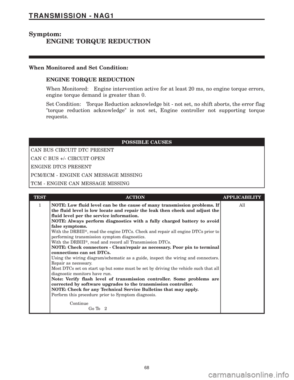
Symptom:
ENGINE TORQUE REDUCTION
When Monitored and Set Condition:
ENGINE TORQUE REDUCTION
When Monitored: Engine intervention active for at least 20 ms, no engine torque errors,
engine torque demand is greater than 0.
Set Condition: Torque Reduction acknowledge bit - not set, no shift aborts, the error flag
9torque reduction acknowledge9is not set, Engine controller not supporting torque
requests.
POSSIBLE CAUSES
CAN BUS CIRCUIT DTC PRESENT
CAN C BUS +/- CIRCUIT OPEN
ENGINE DTCS PRESENT
PCM/ECM - ENGINE CAN MESSAGE MISSING
TCM - ENGINE CAN MESSAGE MISSING
TEST ACTION APPLICABILITY
1NOTE: Low fluid level can be the cause of many transmission problems. If
the fluid level is low locate and repair the leak then check and adjust the
fluid level per the service information.
NOTE: Always perform diagnostics with a fully charged battery to avoid
false symptoms.
With the DRBIIIt, read the engine DTCs. Check and repair all engine DTCs prior to
performing transmission symptom diagnostics.
With the DRBIIIt, read and record all Transmission DTCs.
NOTE: Check connectors - Clean/repair as necessary. Poor pin to terminal
connections can set DTCs.
Using the wiring diagram/schematic as a guide, inspect the wiring and connectors.
Repair as necessary.
Most DTCs set on start up but some must be set by driving the vehicle such that all
diagnostic monitors have run.
Note: Verify flash level of transmission controller. Some problems are
corrected by software upgrades to the transmission controller.
NOTE: Check for any Technical Service Bulletins that may apply.
Perform this procedure prior to Symptom diagnosis.All
Continue
Go To 2
68
TRANSMISSION - NAG1
Page 2234 of 2305
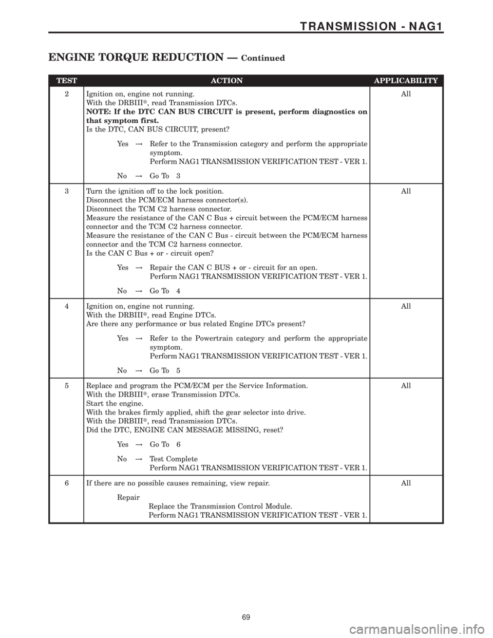
TEST ACTION APPLICABILITY
2 Ignition on, engine not running.
With the DRBIIIt, read Transmission DTCs.
NOTE: If the DTC CAN BUS CIRCUIT is present, perform diagnostics on
that symptom first.
Is the DTC, CAN BUS CIRCUIT, present?All
Ye s!Refer to the Transmission category and perform the appropriate
symptom.
Perform NAG1 TRANSMISSION VERIFICATION TEST - VER 1.
No!Go To 3
3 Turn the ignition off to the lock position.
Disconnect the PCM/ECM harness connector(s).
Disconnect the TCM C2 harness connector.
Measure the resistance of the CAN C Bus + circuit between the PCM/ECM harness
connector and the TCM C2 harness connector.
Measure the resistance of the CAN C Bus - circuit between the PCM/ECM harness
connector and the TCM C2 harness connector.
Is the CAN C Bus + or - circuit open?All
Ye s!Repair the CAN C BUS + or - circuit for an open.
Perform NAG1 TRANSMISSION VERIFICATION TEST - VER 1.
No!Go To 4
4 Ignition on, engine not running.
With the DRBIIIt, read Engine DTCs.
Are there any performance or bus related Engine DTCs present?All
Ye s!Refer to the Powertrain category and perform the appropriate
symptom.
Perform NAG1 TRANSMISSION VERIFICATION TEST - VER 1.
No!Go To 5
5 Replace and program the PCM/ECM per the Service Information.
With the DRBIIIt, erase Transmission DTCs.
Start the engine.
With the brakes firmly applied, shift the gear selector into drive.
With the DRBIIIt, read Transmission DTCs.
Did the DTC, ENGINE CAN MESSAGE MISSING, reset?All
Ye s!Go To 6
No!Test Complete
Perform NAG1 TRANSMISSION VERIFICATION TEST - VER 1.
6 If there are no possible causes remaining, view repair. All
Repair
Replace the Transmission Control Module.
Perform NAG1 TRANSMISSION VERIFICATION TEST - VER 1.
69
TRANSMISSION - NAG1
ENGINE TORQUE REDUCTION ÐContinued
Page 2267 of 2305
Symptom:
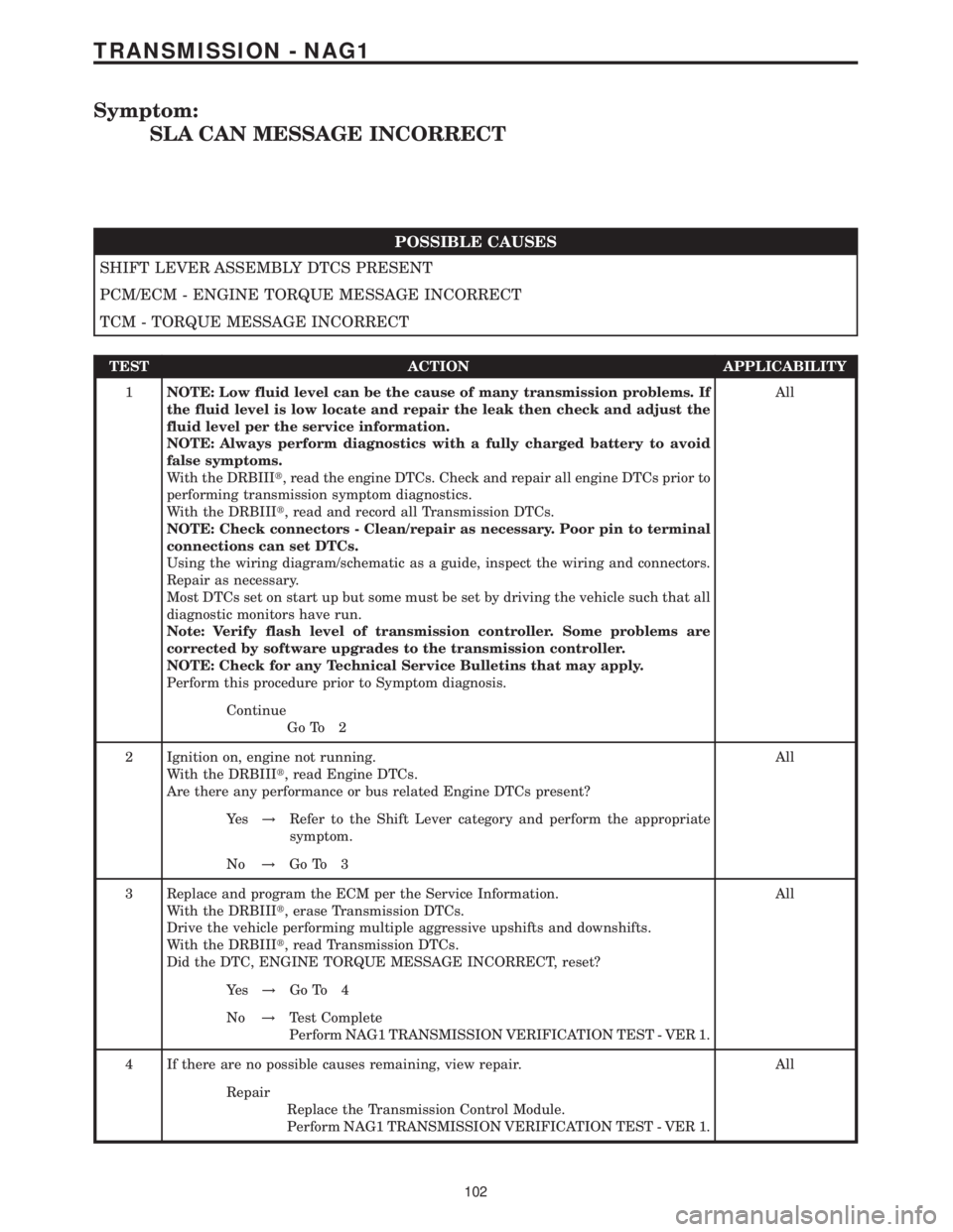
SLA CAN MESSAGE INCORRECT
POSSIBLE CAUSES
SHIFT LEVER ASSEMBLY DTCS PRESENT
PCM/ECM - ENGINE TORQUE MESSAGE INCORRECT
TCM - TORQUE MESSAGE INCORRECT
TEST ACTION APPLICABILITY
1NOTE: Low fluid level can be the cause of many transmission problems. If
the fluid level is low locate and repair the leak then check and adjust the
fluid level per the service information.
NOTE: Always perform diagnostics with a fully charged battery to avoid
false symptoms.
With the DRBIIIt, read the engine DTCs. Check and repair all engine DTCs prior to
performing transmission symptom diagnostics.
With the DRBIIIt, read and record all Transmission DTCs.
NOTE: Check connectors - Clean/repair as necessary. Poor pin to terminal
connections can set DTCs.
Using the wiring diagram/schematic as a guide, inspect the wiring and connectors.
Repair as necessary.
Most DTCs set on start up but some must be set by driving the vehicle such that all
diagnostic monitors have run.
Note: Verify flash level of transmission controller. Some problems are
corrected by software upgrades to the transmission controller.
NOTE: Check for any Technical Service Bulletins that may apply.
Perform this procedure prior to Symptom diagnosis.All
Continue
Go To 2
2 Ignition on, engine not running.
With the DRBIIIt, read Engine DTCs.
Are there any performance or bus related Engine DTCs present?All
Ye s!Refer to the Shift Lever category and perform the appropriate
symptom.
No!Go To 3
3 Replace and program the ECM per the Service Information.
With the DRBIIIt, erase Transmission DTCs.
Drive the vehicle performing multiple aggressive upshifts and downshifts.
With the DRBIIIt, read Transmission DTCs.
Did the DTC, ENGINE TORQUE MESSAGE INCORRECT, reset?All
Ye s!Go To 4
No!Test Complete
Perform NAG1 TRANSMISSION VERIFICATION TEST - VER 1.
4 If there are no possible causes remaining, view repair. All
Repair
Replace the Transmission Control Module.
Perform NAG1 TRANSMISSION VERIFICATION TEST - VER 1.
102
TRANSMISSION - NAG1
Page 2276 of 2305
Symptom:
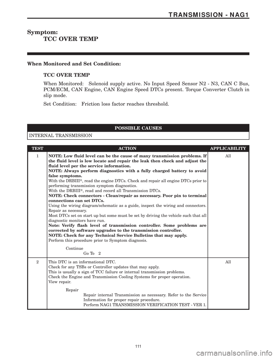
TCC OVER TEMP
When Monitored and Set Condition:
TCC OVER TEMP
When Monitored: Solenoid supply active. No Input Speed Sensor N2 - N3, CAN C Bus,
PCM/ECM, CAN Engine, CAN Engine Speed DTCs present. Torque Converter Clutch in
slip mode.
Set Condition: Friction loss factor reaches threshold.
POSSIBLE CAUSES
INTERNAL TRANSMISSION
TEST ACTION APPLICABILITY
1NOTE: Low fluid level can be the cause of many transmission problems. If
the fluid level is low locate and repair the leak then check and adjust the
fluid level per the service information.
NOTE: Always perform diagnostics with a fully charged battery to avoid
false symptoms.
With the DRBIIIt, read the engine DTCs. Check and repair all engine DTCs prior to
performing transmission symptom diagnostics.
With the DRBIIIt, read and record all Transmission DTCs.
NOTE: Check connectors - Clean/repair as necessary. Poor pin to terminal
connections can set DTCs.
Using the wiring diagram/schematic as a guide, inspect the wiring and connectors.
Repair as necessary.
Most DTCs set on start up but some must be set by driving the vehicle such that all
diagnostic monitors have run.
Note: Verify flash level of transmission controller. Some problems are
corrected by software upgrades to the transmission controller.
NOTE: Check for any Technical Service Bulletins that may apply.
Perform this procedure prior to Symptom diagnosis.All
Continue
Go To 2
2 This DTC is an informational DTC.
Check for any TSBs or Controller updates that may apply.
This is usually a sign of TCC failure or internal transmission problems.
Check the Engine and Transmission Cooling Systems for proper operation.
View repair.All
Repair
Repair internal Transmission as necessary. Refer to the Service
Information for proper repair procedure.
Perform NAG1 TRANSMISSION VERIFICATION TEST - VER 1.
111
TRANSMISSION - NAG1
Page 2280 of 2305
Symptom:
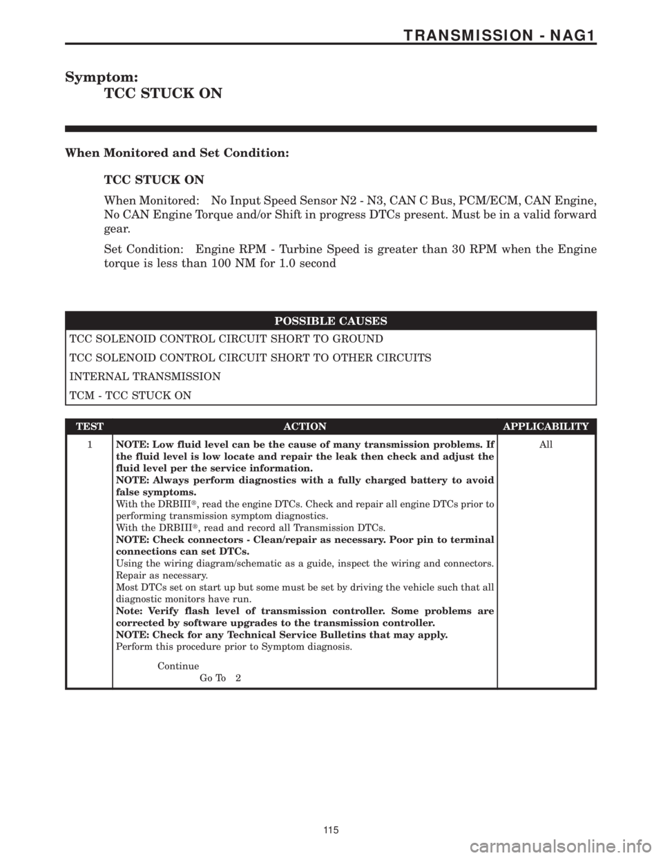
TCC STUCK ON
When Monitored and Set Condition:
TCC STUCK ON
When Monitored: No Input Speed Sensor N2 - N3, CAN C Bus, PCM/ECM, CAN Engine,
No CAN Engine Torque and/or Shift in progress DTCs present. Must be in a valid forward
gear.
Set Condition: Engine RPM - Turbine Speed is greater than 30 RPM when the Engine
torque is less than 100 NM for 1.0 second
POSSIBLE CAUSES
TCC SOLENOID CONTROL CIRCUIT SHORT TO GROUND
TCC SOLENOID CONTROL CIRCUIT SHORT TO OTHER CIRCUITS
INTERNAL TRANSMISSION
TCM - TCC STUCK ON
TEST ACTION APPLICABILITY
1NOTE: Low fluid level can be the cause of many transmission problems. If
the fluid level is low locate and repair the leak then check and adjust the
fluid level per the service information.
NOTE: Always perform diagnostics with a fully charged battery to avoid
false symptoms.
With the DRBIIIt, read the engine DTCs. Check and repair all engine DTCs prior to
performing transmission symptom diagnostics.
With the DRBIIIt, read and record all Transmission DTCs.
NOTE: Check connectors - Clean/repair as necessary. Poor pin to terminal
connections can set DTCs.
Using the wiring diagram/schematic as a guide, inspect the wiring and connectors.
Repair as necessary.
Most DTCs set on start up but some must be set by driving the vehicle such that all
diagnostic monitors have run.
Note: Verify flash level of transmission controller. Some problems are
corrected by software upgrades to the transmission controller.
NOTE: Check for any Technical Service Bulletins that may apply.
Perform this procedure prior to Symptom diagnosis.All
Continue
Go To 2
11 5
TRANSMISSION - NAG1