2006 MERCEDES-BENZ SPRINTER starter
[x] Cancel search: starterPage 1618 of 2305
(3) Install the retaining lock for the crankshaft/
ring gear.
NOTE: If the hub of the belt pulley/vibration damper
is tight, use a puller to remove it. Do Not tilt the
puller. The groves of the puller MUST mesh fully
into the slots of the belt pulley.
NOTE: Inspect the running surface of the belt pulley
for wear.
(4) Remove the belt pully/vibration damper.
CAUTION: Care must be taken to prevent severe
damage to the crankshaft and mounting whole for
the front crankshaft seal.
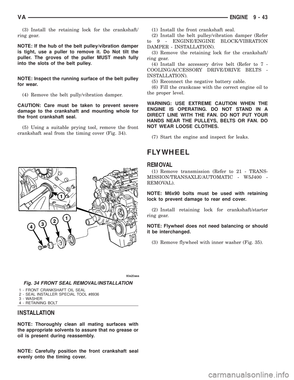
(5) Using a suitable prying tool, remove the front
crankshaft seal from the timing cover (Fig. 34).
INSTALLATION
NOTE: Thoroughly clean all mating surfaces with
the appropriate solvents to assure that no grease or
oil is present during reassembly.
NOTE: Carefully position the front crankshaft seal
evenly onto the timing cover.(1) Install the front crankshaft seal.
(2) Install the belt pulley/vibration damper (Refer
to 9 - ENGINE/ENGINE BLOCK/VIBRATION
DAMPER - INSTALLATION).
(3) Remove the retaining lock for the crankshaft/
ring gear.
(4) Install the accessory drive belt (Refer to 7 -
COOLING/ACCESSORY DRIVE/DRIVE BELTS -
INSTALLATION).
(5) Reconnect the negative battery cable.
(6) Fill the crankcase with the correct engine oil to
the proper level.
WARNING: USE EXTREME CAUTION WHEN THE
ENGINE IS OPERATING. DO NOT STAND IN A
DIRECT LINE WITH THE FAN. DO NOT PUT YOUR
HANDS NEAR THE PULLEYS, BELTS OR FAN. DO
NOT WEAR LOOSE CLOTHES.
(7) Start the engine and inspect for leaks.
FLYWHEEL
REMOVAL
(1) Remove transmission (Refer to 21 - TRANS-
MISSION/TRANSAXLE/AUTOMATIC - W5J400 -
REMOVAL).
NOTE: M6x90 bolts must be used with retaining
lock to prevent damage to rear end cover.
(2) Install retaining lock for crankshaft/starter
ring gear.
NOTE: Flywheel does not need balancing or should
it be interchanged.
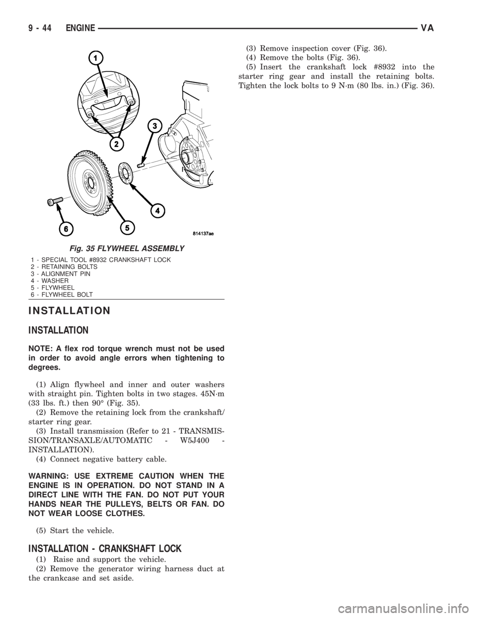
(3) Remove flywheel with inner washer (Fig. 35).
Fig. 34 FRONT SEAL REMOVAL/INSTALLATION
1 - FRONT CRANKSHAFT OIL SEAL
2 - SEAL INSTALLER SPECIAL TOOL #8936
3 - WASHER
4 - RETAINING BOLT
VAENGINE 9 - 43
Page 1619 of 2305
INSTALLATION
INSTALLATION
NOTE: A flex rod torque wrench must not be used
in order to avoid angle errors when tightening to
degrees.
(1) Align flywheel and inner and outer washers
with straight pin. Tighten bolts in two stages. 45N´m
(33 lbs. ft.) then 90É (Fig. 35).
(2) Remove the retaining lock from the crankshaft/
starter ring gear.
(3) Install transmission (Refer to 21 - TRANSMIS-
SION/TRANSAXLE/AUTOMATIC - W5J400 -
INSTALLATION).
(4) Connect negative battery cable.
WARNING: USE EXTREME CAUTION WHEN THE
ENGINE IS IN OPERATION. DO NOT STAND IN A
DIRECT LINE WITH THE FAN. DO NOT PUT YOUR
HANDS NEAR THE PULLEYS, BELTS OR FAN. DO
NOT WEAR LOOSE CLOTHES.
(5) Start the vehicle.
INSTALLATION - CRANKSHAFT LOCK
(1) Raise and support the vehicle.
(2) Remove the generator wiring harness duct at
the crankcase and set aside.(3) Remove inspection cover (Fig. 36).
(4) Remove the bolts (Fig. 36).
(5) Insert the crankshaft lock #8932 into the
starter ring gear and install the retaining bolts.
Tighten the lock bolts to 9 N´m (80 lbs. in.) (Fig. 36).
Fig. 35 FLYWHEEL ASSEMBLY
1 - SPECIAL TOOL #8932 CRANKSHAFT LOCK
2 - RETAINING BOLTS
3 - ALIGNMENT PIN
4 - WASHER
5 - FLYWHEEL
6 - FLYWHEEL BOLT
9 - 44 ENGINEVA
Page 1645 of 2305
(8) Install the exhaust hanger fasteners at the
muffler.
(9) Tighten the exhaust hanger bracket to engine
block.
(10) Install the turbocharger support bracket.
(11) Lower the vehicle.
(12) Install the air cleaner duct to the turbo-
charger (Fig. 71).
(13) Install the exhaust heat shield.
(14) Connect the negative battery cable.
TIMING CHAIN COVER
REMOVAL
WARNING: DO NOT OPEN COOLING SYSTEM
UNLESS TEMPERATURE IS BELOW 90ÉC (194ÉF).
OPEN CAP SLOWLY TO RELEASE PRESSURE.
STORE COOLANT IN APPROVED CONTAINER
ONLY. RISK OF INJURY TO SKIN AND EYES FROM
SCALDING COOLANT. WEAR PROTECTIVE
GLOVES, CLOTHING AND EYE WEAR.
(1) Disconnect negative battery cable.
NOTE: Rotate engine on crankshaft. DO NOT crank
the engine at the bolt of the camshaft sprocket.
NOTE: DO NOT crank engine back.
(2) Position piston of cylinder 1 to ignition TDC.
Markings on the camshaft bearing cap must be
aligned.
(3) Drain coolant (Refer to 7 - COOLING/ENGINE/
COOLANT - STANDARD PROCEDURE).
(4) Install retaining lock for crankshaft/starter
ring gear (Refer to 9 - ENGINE/ENGINE BLOCK/
FLEX PLATE - INSTALLATION).
(5) Drain engine oil.
(6) Remove the oil filter to allow the oil to flow off
into the oil pan.
(7) Remove the radiator assembly (Refer to 7 -
COOLING/ENGINE/RADIATOR - REMOVAL).
(8) Remove engine cover (Refer to 9 - ENGINE -
REMOVAL).
(9) Remove front cover at cylinder head (Refer to 9
- ENGINE/CYLINDER HEAD - REMOVAL).
(10) Remove accessory drive belt.
(11) Remove the high pressure fuel pump (Refer to
14 - FUEL SYSTEM/FUEL DELIVERY/FUEL PUMP
- REMOVAL).
(12) Remove water pump (Refer to 7 - COOLING/
ENGINE/WATER PUMP - REMOVAL).
(13) Remove accessory drive belt pulley and vibra-
tion damper (Refer to 9 - ENGINE/ENGINE BLOCK/
VIBRATION DAMPER - REMOVAL).
(14) Remove the power steering pump.NOTE: NO NOT open the air conditioning system.
(15) Unplug AC compressor electrical connector
and unbolt AC compressor. Relocate in lower engine
compartmentwith outopening the system.
(16) Remove the generator with wiring attached
and relocate somewhere in the engine compartment.
(17) Install engine support fixture.
(18) Remove the oil pan.
(19) Detach the coolant hose to oil-water heat
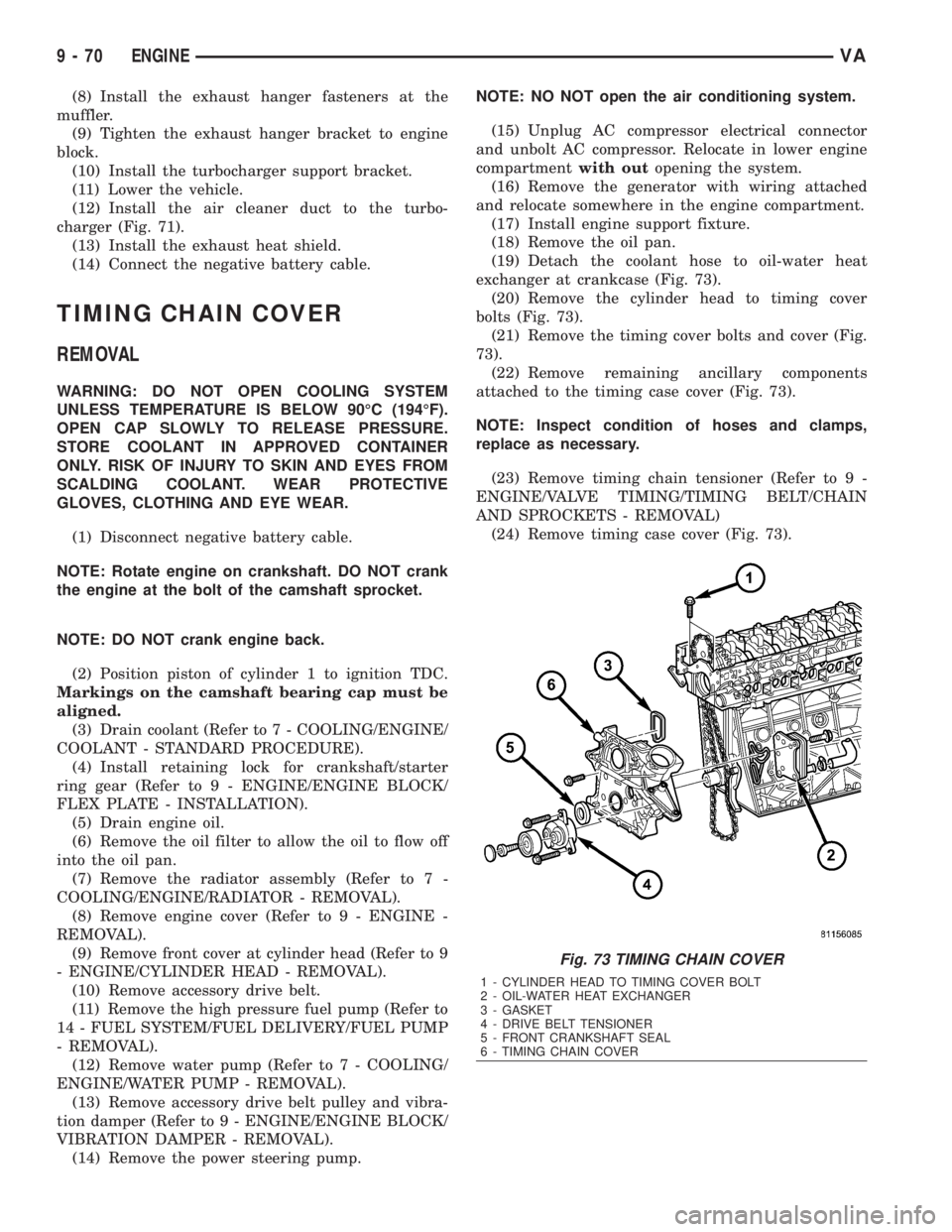
exchanger at crankcase (Fig. 73).
(20) Remove the cylinder head to timing cover
bolts (Fig. 73).
(21) Remove the timing cover bolts and cover (Fig.
73).
(22) Remove remaining ancillary components
attached to the timing case cover (Fig. 73).
NOTE: Inspect condition of hoses and clamps,
replace as necessary.
(23) Remove timing chain tensioner (Refer to 9 -
ENGINE/VALVE TIMING/TIMING BELT/CHAIN
AND SPROCKETS - REMOVAL)
(24) Remove timing case cover (Fig. 73).
Fig. 73 TIMING CHAIN COVER
1 - CYLINDER HEAD TO TIMING COVER BOLT
2 - OIL-WATER HEAT EXCHANGER
3 - GASKET
4 - DRIVE BELT TENSIONER
5 - FRONT CRANKSHAFT SEAL
6 - TIMING CHAIN COVER
9 - 70 ENGINEVA
Page 1646 of 2305
INSTALLATION
CAUTION: Care must be taken to closley inspect
the gasket area around the time case cover to cyl-
inder head gasket coolant port. If damage is found,
replace the cylinder head gasket. Failure to do so
may result in engine damage.
NOTE: Thoroughly clean all mating surfaces with
the appropriate solvents to assure that no grease or
oil is present during assembly.
(1) Inspect cylinder head gasket and oil pan gas-
ket. If damaged, replace.
(2) Replace the front crankshaft seal (Refer to 9 -
ENGINE/ENGINE BLOCK/CRANKSHAFT OIL
SEAL - FRONT - INSTALLATION).
(3) Install ancillary components to timing case
cover.
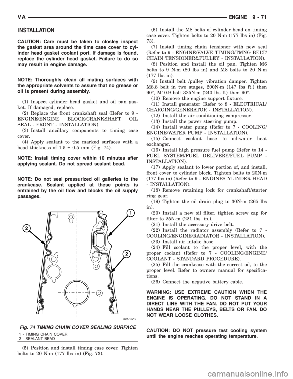
(4) Apply sealant to the marked surfaces with a
bead thickness of 1.5 0.5 mm (Fig. 74).
NOTE: Install timing cover within 10 minutes after
applying sealant. Do not spread sealant bead.
NOTE: Do not seal pressurized oil galleries to the
crankcase. Sealant applied at these points is
entrained by the oil flow and blocks the oil supply
passages.
(5) Position and install timing case cover. Tighten
bolts to 20 N´m (177 lbs in) (Fig. 73).(6) Install the M8 bolts of cylinder head on timing
case cover. Tighten bolts to 20 N´m (177 lbs in) (Fig.
73).
(7) Install timing chain tensioner with new seal
(Refer to 9 - ENGINE/VALVE TIMING/TMNG BELT/
CHAIN TENSIONER&PULLEY - INSTALLATION).
(8) Position and install the oil pan. Tighten M6
bolts to 9 N´m (80 lbs in) and M8 bolts to 20 N´m
(177 lbs in).
(9) Install belt /pulley vibration damper. Tighten
M8.8 bolt in two stages, 200N´m (147 lbs ft.) then
90É, M10.9 bolt 325N´m (240 lbs ft) then 90É.
(10) Remove the engine support fixture.
(11) Install generator (Refer to 8 - ELECTRICAL/
CHARGING/GENERATOR - INSTALLATION).
(12) Install the air conditioning compressor.
(13) Install the power steering pump.
(14) Install water pump (Refer to 7 - COOLING/
ENGINE/WATER PUMP - INSTALLATION).
(15) Connect coolant hose to oil-water heat
exchanger.
(16) Install high pressure fuel pump (Refer to 14 -
FUEL SYSTEM/FUEL DELIVERY/FUEL PUMP -
INSTALLATION).
(17) Apply sealant to lower portion of, and install,
front cover to cylinder block. Tighten bolts to 20N´m
(177 lbs in) (Refer to 9 - ENGINE/CYLINDER HEAD
- INSTALLATION).
(18) Remove retaining lock for crankshaft/starter
ring gear.
(19) Tighten the oil drain plug to 30N´m (265 lbs
in).
(20) Install a new oil filter. tighten screw cap for
filter to 25N´m (221 lbs. in.).
(21) Install the accessory drive belt.
(22) Install the radiator assembly (Refer to 7 -
COOLING/ENGINE/RADIATOR - INSTALLATION).
(23) Install air intake hose.
(24) Fill coolant to the proper level, with the
proper coolant (Refer to 7 - COOLING/ENGINE/
COOLANT - STANDARD PROCEDURE).
(25) Fill the crankcase with the correct oil, to the
proper level. Refer to owners manual for specifica-
tions.
(26) Connect the negative battery cable.
WARNING: USE EXTREME CAUTION WHEN THE
ENGINE IS OPERATING. DO NOT STAND IN A
DIRECT LINE WITH THE FAN. DO NOT PUT YOUR
HANDS NEAR THE PULLEYS, BELTS OR FAN. DO
NOT WEAR LOOSE CLOTHES.
CAUTION: DO NOT pressure test cooling system
until the engine reaches operating temperature.
Fig. 74 TIMING CHAIN COVER SEALING SURFACE
1 - TIMING CHAIN COVER
2 - SEALANT BEAD
VAENGINE 9 - 71
Page 1716 of 2305
(3) Install engine cover.
(4) Reconnect negative battery cable.
CRANKSHAFT POSITION SEN-
SOR
DESCRIPTION
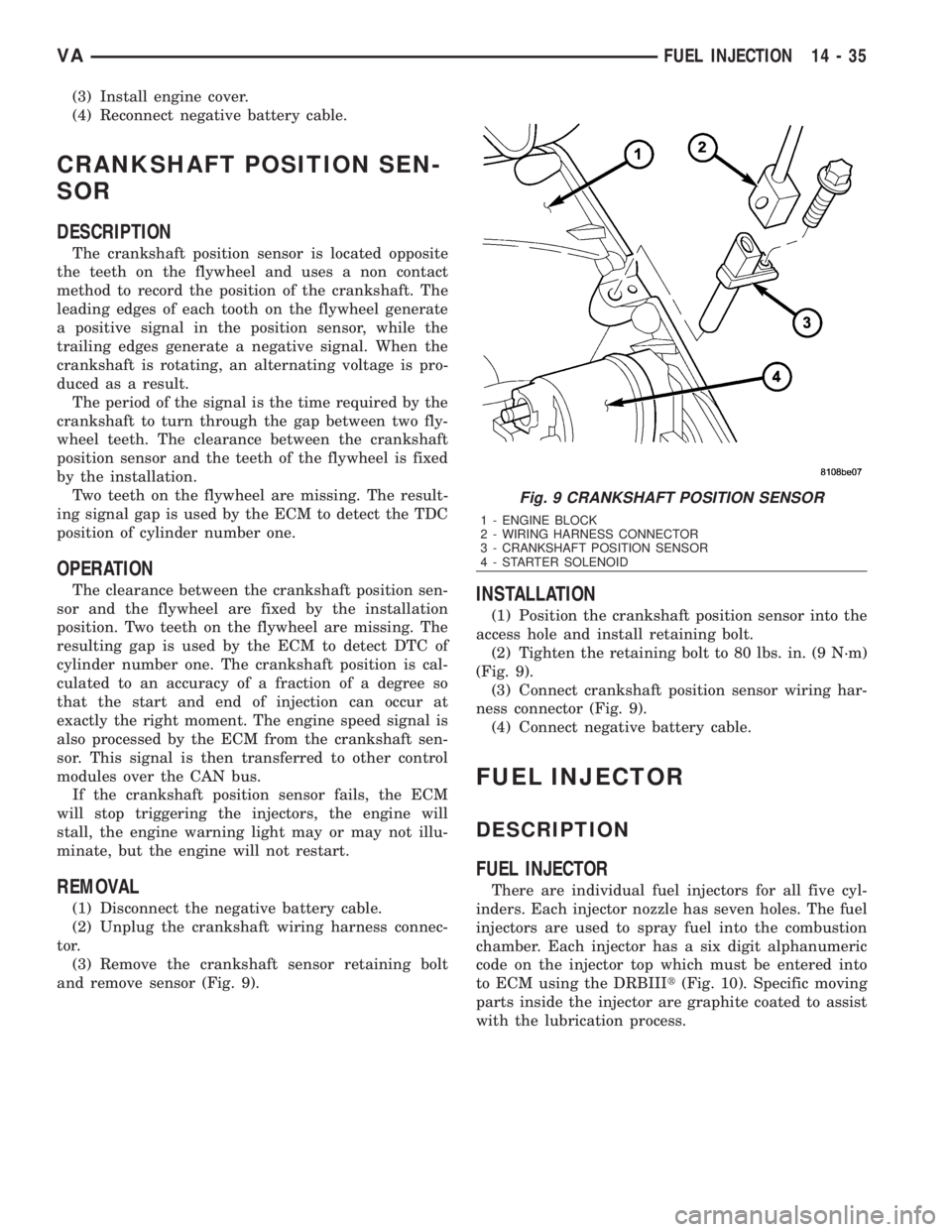
The crankshaft position sensor is located opposite
the teeth on the flywheel and uses a non contact
method to record the position of the crankshaft. The
leading edges of each tooth on the flywheel generate
a positive signal in the position sensor, while the
trailing edges generate a negative signal. When the
crankshaft is rotating, an alternating voltage is pro-
duced as a result.
The period of the signal is the time required by the
crankshaft to turn through the gap between two fly-
wheel teeth. The clearance between the crankshaft
position sensor and the teeth of the flywheel is fixed
by the installation.
Two teeth on the flywheel are missing. The result-
ing signal gap is used by the ECM to detect the TDC
position of cylinder number one.
OPERATION
The clearance between the crankshaft position sen-
sor and the flywheel are fixed by the installation
position. Two teeth on the flywheel are missing. The
resulting gap is used by the ECM to detect DTC of
cylinder number one. The crankshaft position is cal-
culated to an accuracy of a fraction of a degree so
that the start and end of injection can occur at
exactly the right moment. The engine speed signal is
also processed by the ECM from the crankshaft sen-
sor. This signal is then transferred to other control
modules over the CAN bus.
If the crankshaft position sensor fails, the ECM
will stop triggering the injectors, the engine will
stall, the engine warning light may or may not illu-
minate, but the engine will not restart.
REMOVAL
(1) Disconnect the negative battery cable.
(2) Unplug the crankshaft wiring harness connec-
tor.
(3) Remove the crankshaft sensor retaining bolt
and remove sensor (Fig. 9).
INSTALLATION
(1) Position the crankshaft position sensor into the
access hole and install retaining bolt.
(2) Tighten the retaining bolt to 80 lbs. in. (9 N´m)
(Fig. 9).
(3) Connect crankshaft position sensor wiring har-
ness connector (Fig. 9).
(4) Connect negative battery cable.
FUEL INJECTOR
DESCRIPTION
FUEL INJECTOR
There are individual fuel injectors for all five cyl-
inders. Each injector nozzle has seven holes. The fuel
injectors are used to spray fuel into the combustion
chamber. Each injector has a six digit alphanumeric
code on the injector top which must be entered into
to ECM using the DRBIIIt(Fig. 10). Specific moving
parts inside the injector are graphite coated to assist
with the lubrication process.
Fig. 9 CRANKSHAFT POSITION SENSOR
1 - ENGINE BLOCK
2 - WIRING HARNESS CONNECTOR
3 - CRANKSHAFT POSITION SENSOR
4 - STARTER SOLENOID
VAFUEL INJECTION 14 - 35
Page 1848 of 2305
(0.114 in.), 3.2 mm (0.126 in.), and 3.5 mm (0.138
in.).
ELECTROHYDRAULIC UNIT
DESCRIPTION
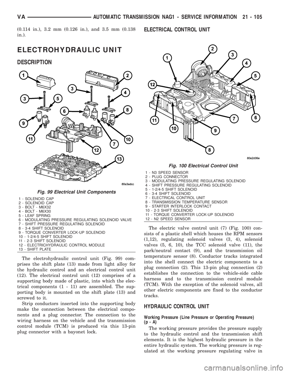
The electrohydraulic control unit (Fig. 99) com-
prises the shift plate (13) made from light alloy for
the hydraulic control and an electrical control unit
(12). The electrical control unit (12) comprises of a
supporting body made of plastic, into which the elec-
trical components (1 - 11) are assembled. The sup-
porting body is mounted on the shift plate (13) and
screwed to it.
Strip conductors inserted into the supporting body
make the connection between the electrical compo-
nents and a plug connector. The connection to the
wiring harness on the vehicle and the transmission
control module (TCM) is produced via this 13-pin
plug connector with a bayonet lock.
ELECTRICAL CONTROL UNIT
The electric valve control unit (7) (Fig. 100) con-
sists of a plastic shell which houses the RPM sensors
(1,12), regulating solenoid valves (3, 4), solenoid
valves (5, 6, 10), the TCC solenoid valve (11), the
park/neutral contact (9), and the transmission oil
temperature sensor (8). Conductor tracks integrated
into the shell connect the electric components to a
plug connection (2). This 13-pin plug connection (2)
establishes the connection to the vehicle-side cable
harness and to the transmission control module
(TCM). With the exception of the solenoid valves, all
other electric components are fixed to the conductor
tracks.
HYDRAULIC CONTROL UNIT
Working Pressure (Line Pressure or Operating Pressure)
(p-A)
The working pressure provides the pressure supply
to the hydraulic control and the transmission shift
elements. It is the highest hydraulic pressure in the
entire hydraulic system. The working pressure is reg-
ulated at the working pressure regulating valve in
Fig. 99 Electrical Unit Components
1 - SOLENOID CAP
2 - SOLENOID CAP
3 - BOLT - M6X32
4 - BOLT - M6X30
5 - LEAF SPRING
6 - MODULATING PRESSURE REGULATING SOLENOID VALVE
7 - SHIFT PRESSURE REGULATING SOLENOID
8 - 3-4 SHIFT SOLENOID
9 - TORQUE CONVERTER LOCK-UP SOLENOID
10 - 1-2/4-5 SHIFT SOLENOID
11 - 2-3 SHIFT SOLENOID
12 - ELECTRICHYDRAULIC CONTROL MODULE
13 - SHIFT PLATE
Fig. 100 Electrical Control Unit
1 - N3 SPEED SENSOR
2 - PLUG CONNECTOR
3 - MODULATING PRESSURE REGULATING SOLENOID
4 - SHIFT PRESSURE REGULATING SOLENOID
5 - 1-2/4-5 SHIFT SOLENOID
6 - 3-4 SHIFT SOLENOID
7 - ELECTRICAL CONTROL UNIT
8 - TRANSMISSION TEMPERATURE SENSOR
9 - STARTER INTERLOCK CONTACT
10 - 2-3 SHIFT SOLENOID
11 - TORQUE CONVERTER LOCK-UP SOLENOID
12 - N2 SPEED SENSOR
VAAUTOMATIC TRANSMISSION NAG1 - SERVICE INFORMATION 21 - 105
Page 1855 of 2305
Regulating Valve Pressure Regulating Valve
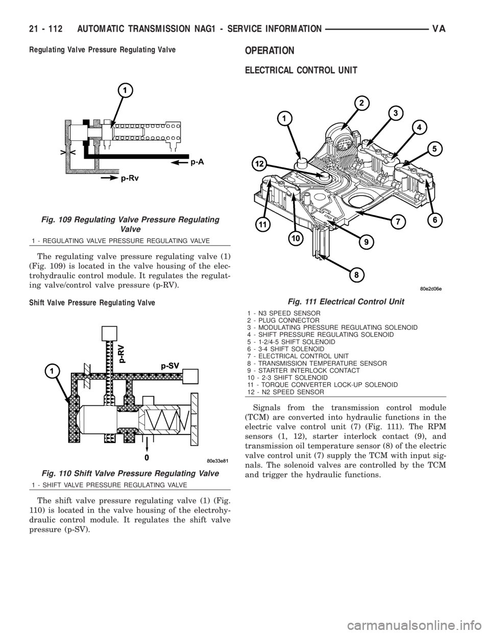
The regulating valve pressure regulating valve (1)
(Fig. 109) is located in the valve housing of the elec-
trohydraulic control module. It regulates the regulat-
ing valve/control valve pressure (p-RV).
Shift Valve Pressure Regulating Valve
The shift valve pressure regulating valve (1) (Fig.
110) is located in the valve housing of the electrohy-
draulic control module. It regulates the shift valve
pressure (p-SV).OPERATION
ELECTRICAL CONTROL UNIT
Signals from the transmission control module
(TCM) are converted into hydraulic functions in the
electric valve control unit (7) (Fig. 111). The RPM
sensors (1, 12), starter interlock contact (9), and
transmission oil temperature sensor (8) of the electric
valve control unit (7) supply the TCM with input sig-
nals. The solenoid valves are controlled by the TCM
and trigger the hydraulic functions.
Fig. 109 Regulating Valve Pressure Regulating
Valve
1 - REGULATING VALVE PRESSURE REGULATING VALVE
Fig. 110 Shift Valve Pressure Regulating Valve
1 - SHIFT VALVE PRESSURE REGULATING VALVE
Fig. 111 Electrical Control Unit
1 - N3 SPEED SENSOR
2 - PLUG CONNECTOR
3 - MODULATING PRESSURE REGULATING SOLENOID
4 - SHIFT PRESSURE REGULATING SOLENOID
5 - 1-2/4-5 SHIFT SOLENOID
6 - 3-4 SHIFT SOLENOID
7 - ELECTRICAL CONTROL UNIT
8 - TRANSMISSION TEMPERATURE SENSOR
9 - STARTER INTERLOCK CONTACT
10 - 2-3 SHIFT SOLENOID
11 - TORQUE CONVERTER LOCK-UP SOLENOID
12 - N2 SPEED SENSOR
21 - 112 AUTOMATIC TRANSMISSION NAG1 - SERVICE INFORMATIONVA
Page 1920 of 2305
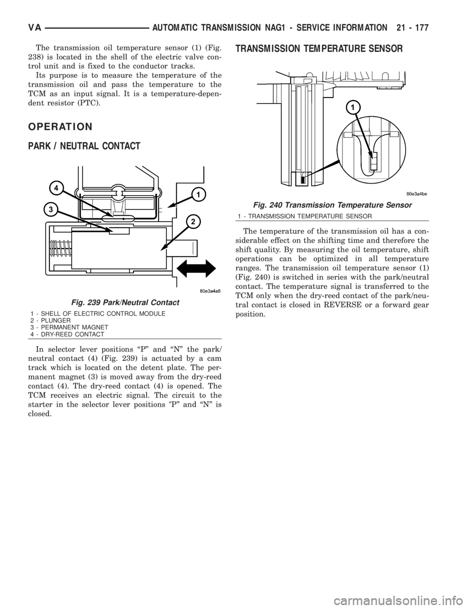
The transmission oil temperature sensor (1) (Fig.
238) is located in the shell of the electric valve con-
trol unit and is fixed to the conductor tracks.
Its purpose is to measure the temperature of the
transmission oil and pass the temperature to the
TCM as an input signal. It is a temperature-depen-
dent resistor (PTC).
OPERATION
PARK / NEUTRAL CONTACT
In selector lever positions ªPº and ªNº the park/
neutral contact (4) (Fig. 239) is actuated by a cam
track which is located on the detent plate. The per-
manent magnet (3) is moved away from the dry-reed
contact (4). The dry-reed contact (4) is opened. The
TCM receives an electric signal. The circuit to the
starter in the selector lever positions9Pº and ªNº is
closed.
TRANSMISSION TEMPERATURE SENSOR
The temperature of the transmission oil has a con-
siderable effect on the shifting time and therefore the
shift quality. By measuring the oil temperature, shift
operations can be optimized in all temperature
ranges. The transmission oil temperature sensor (1)
(Fig. 240) is switched in series with the park/neutral
contact. The temperature signal is transferred to the
TCM only when the dry-reed contact of the park/neu-
tral contact is closed in REVERSE or a forward gear
position.
Fig. 239 Park/Neutral Contact
1 - SHELL OF ELECTRIC CONTROL MODULE
2 - PLUNGER
3 - PERMANENT MAGNET
4 - DRY-REED CONTACT
Fig. 240 Transmission Temperature Sensor
1 - TRANSMISSION TEMPERATURE SENSOR
VAAUTOMATIC TRANSMISSION NAG1 - SERVICE INFORMATION 21 - 177