2006 MERCEDES-BENZ SPRINTER starter
[x] Cancel search: starterPage 683 of 2305

ENGINE CONTROL MODULE C2 (OBD)CAV CIRCUIT FUNCTION
1 16BK/RD FUSED ENGINE CONTROL RELAY OUTPUT
2 14BR GROUND
3 14BK/BL FUSED ENGINE CONTROL RELAY OUTPUT
4 14BR GROUND
5 14BK/BL FUSED ENGINE CONTROL RELAY OUTPUT
6 14BR GROUND
7 18RD S/C SWITCH 12 VOLT SUPPLY
8 18BR/WT HIGH IDLE ON SIGNAL
10 18WT/RD BOOST PRESSURE SENSOR 5 VOLT SUPPLY
11 18WT/DG BOOST PRESSURE SENSOR SIGNAL
12 18BR/WT SENSOR GROUND
13 18GY/DG ACCEL PEDAL POSITION SENSOR SIGNAL NO. 2
14 18BR/GY ACCEL PEDAL POSITION SENSOR GROUND NO. 2
17 18BR/DG KICKDOWN SWITCH SIGNAL
18 20DG/YL ENGINE RPM
19 18BK FUSED IGNITION SWITCH OUTPUT (RUN-START)
24 18BL/RD ACCEL PEDAL POSITION SENSOR 5 VOLT SUPPLY
25 18BL/DG ACCEL PEDAL POSITION SENSOR SIGNAL NO. 1
26 18BR/BL ACCEL PEDAL POSITION SENSOR GROUND NO. 1
28 18BR/DG INTAKE AIR TEMPERATURE SENSOR GROUND
31 20BL/YL K-ECM
32 20DG ENHANCED ACCIDENT REPORT DRIVER
36 18VT IGNITION SWITCH OUTPUT (START)
37 18DG ACCEL/SET SIGNAL
38 18BK VERIFICATION SIGNAL
42 18DG/WT INTAKE AIR TEMPERATURE SENSOR SIGNAL
43 18BK/RD GLOW PLUG MODULE CONTROL
44 18YL/BL ENGINE CONTROL RELAY CONTROL
50 18YL DECEL/SET SIGNAL
51 18GY OFF SIGNAL
52 18BL RESUME SIGNAL
53 20DG/WT CAN C BUS (+)
54 20DG CAN C BUS (-)
55 18BR/RD FUEL PUMP RELAY CONTROL
58 18VT/DG STARTER MOTOR RELAY CONTROL
ENGINE COOLANT TEMPERATURE SENSOR - BLACKCAV CIRCUIT FUNCTION
1 20BR/WT ENGINE COOLANT TEMPERATURE SENSOR GROUND
2 20DG/RD ENGINE COOLANT TEMPERATURE SENSOR SIGNAL
C
O
N
N
E
C
T
O
R
P
I
N
O
U
T
S
260
CONNECTOR PINOUTS
Page 692 of 2305
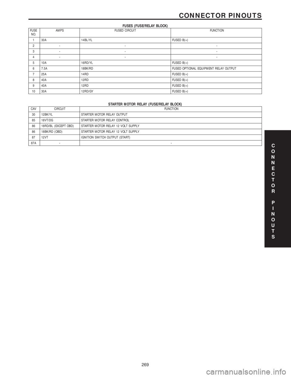
FUSES (FUSE/RELAY BLOCK)FUSE
NO.AMPS FUSED CIRCUIT FUNCTION
1 30A 14BL/YL FUSED B(+)
2- - -
3- - -
4- - -
5 10A 16RD/YL FUSED B(+)
6 7.5A 18BK/RD FUSED OPTIONAL EQUIPMENT RELAY OUTPUT
7 25A 14RD FUSED B(+)
8 40A 12RD FUSED B(+)
9 40A 12RD FUSED B(+)
10 30A 12RD/GY FUSED B(+)
STARTER MOTOR RELAY (FUSE/RELAY BLOCK)CAV CIRCUIT FUNCTION
30 12BK/YL STARTER MOTOR RELAY OUTPUT
85 18VT/DG STARTER MOTOR RELAY CONTROL
86 18RD/BL (EXCEPT OBD) STARTER MOTOR RELAY 12 VOLT SUPPLY
86 18BK/RD (OBD) STARTER MOTOR RELAY 12 VOLT SUPPLY
87 12VT IGNITION SWITCH OUTPUT (START)
87A --
C
O
N
N
E
C
T
O
R
P
I
N
O
U
T
S
269
CONNECTOR PINOUTS
Page 722 of 2305
(6) Start the engine in the vehicle which has the
booster battery, let the engine idle a few minutes,
then start the engine in the vehicle with the dis-
charged battery.
CAUTION: Do not crank starter motor on disabled
vehicle for more than 15 seconds, starter will over-
heat and could fail.
(7) Allow battery in disabled vehicle to charge to
at least 12.4 volts (75% charge) before attempting to
start engine. If engine does not start within 15 sec-
onds, stop cranking engine and allow starter to cool
(15 min.), before cranking again.
DISCONNECT CABLE CLAMPS AS FOLLOWS:
²Disconnect BLACK cable clamp from engine
ground on disabled vehicle.
²When using a Booster vehicle, disconnect
BLACK cable clamp from battery negative terminal.
Disconnect RED cable clamp from battery positive
terminal.
²Disconnect RED cable clamp from battery posi-
tive terminal on disabled vehicle.
TOWING
STANDARD PROCEDURE - TOWING
WARNING: Do not tow the vehicle if the key cannot
be turned in the ignition lock. If the key cannot be
turned, the ignition lock remains locked and the
vehicle cannot be steered. With the engine not run-
ning there is no power assistance for the braking
and steering systems. In this case, it is important to
keep in mind that a considerably higher degree of
effort is necessary to brake and steer the vehicle.
The vehicle must not be towed with the front axle
raised and the key in position 2 in the ignition lock
as the drive wheels could then lock due to the
acceleration skid control (ASR)
If the Engine is Damaged
For towing distances up to 30 miles (about 50
km)
²Shift selector lever in ªNº position.
²Do not exceed a towing speed of 30 m.p.h. (50
km/h).
For towing distances greater than 30 mile
(about 50 km)
²Remove the propeller shafts leading to the drive
axles. The vehicle can be towed without restriction.
If the Transmission is Damaged
²Remove the propeller shafts leading to the drive
axles. The vehicle can be towed without restriction.
If the Front Axle is Damaged
²Raise the front axle.
²Observe the same towing restrictions as for
engine damage.
If the Rear Axle is Damaged
²Raise the rear axle.
NOTE: Comply with local legal regulations regard-
ing towing vehicles.
SAFETY PRECAUTIONS
NOTE: The following safety precautions must be
observed when towing a vehicle.
²Secure loose and protruding parts.
²Always use a safety chain system that is inde-
pendent of the lifting and towing equipment.
²Do not allow towing equipment to contact the
disabled vehicle's fuel tank.
²Do not allow anyone under the disabled vehicle
while it is lifted by the towing device.
²Do not allow passengers to ride in a vehicle
being towed.
²Always observe state and local laws regarding
towing regulations.
²Do not tow a vehicle in a manner that could
jeopardize the safety of the operator, pedestrians or
other motorists.
²Do not attach tow chains, T-hooks, J-hooks, or a
tow sling to a bumper, steering linkage, drive shafts
or a non-reinforced frame hole.
²Remove exhaust pipe tips that interfere with the
tow sling and crossbar
²Padding should be placed between the tow sling/
crossbar and any painted surfaces
²When placing tow hooks on the rear axle, posi-
tion them so they do not damage the brake tubing or
hoses
²Do not tow the vehicle by connecting to the front
or rear shock absorbers
²Do not tow a heavily loaded vehicle. Damage to
the vehicle may result. Use a flatbed device to trans-
port a loaded vehicle.
GROUND CLEARANCE
CAUTION: If vehicle is towed with wheels removed,
install lug nuts to retain brake drums.
A towed vehicle should be raised until lifted wheels
are a minimum 100 mm (4 in) from the ground. Be
sure there is adequate ground clearance at the oppo-
site end of the vehicle, especially when towing over
rough terrain, steep rises in the road or if the vehicle
is equipped with air dams, spoilers, and/or ground
VALUBRICATION & MAINTENANCE 0 - 7
Page 859 of 2305

ECM Control Strategy The engine control module
is involved with a variety of functions such as: (Fig.
3)
²Individual injector activation
²Engine idle speed control to ensure smooth
engine idling independent of engine load
²Ride comfort function such as anti jerk control:
The CDI control module detects irregularities in
engine speed (resulting, for example, from load
changes or gear shift) from the signal supplied by the
crankshaft position sensor and reduces them by
adjusting the quantity injected into each of the cylin-
ders
²Constant RPM (high idle feature) for ambulance
vehicle bodies equipped with electrical appliances
²Starter control, immobilizer, cruise control, kick
down, air conditioner
²Maintenance computer ASSYST (optional)
²Glow plug for pre-heating, post heating and
intermittent heating
²Error code memory/diagnostics, communication
interface for diagnosis and handling the fault codes
²The maximum vehicle speed is programmable
from 19±82 m.p.h. The standard is 82 m.p.h.
Fig. 2 ECM
1 - MASS AIR FLOW SENSOR 8 - CHARGE AIR PRESSURE SENSOR
2 - TURBOCHARGER SERVO MOTOR 9 - CHARGE AIR TEMPERATURE SENSOR
3 - CAMSHAFT POSITION SENSOR 10 - COOLANT TEMPERATURE SENSOR
4 - ENGINE OIL SENSOR 11 - FUEL RAIL PRESSURE SENSOR
5 - CRANKSHAFT POSITION SENSOR 12 - FUEL TEMPERATURE SENSOR
6 - PRESSURE REGULATOR VALVE 13 - FUEL QUANTITY CONTROL VALVE
7 - EGR VALVE 14 - AIR INTAKE PRESSURE SENSOR
8E - 4 ELECTRONIC CONTROL MODULESVA
Page 862 of 2305

²Position of selector lever.
²Selected shift range.
²CAN signals.
²Engine Status.
Engine speed limits may be reached in all gears
with full throttle or in kick-down operation. In for-
ward driving, the shift range of the forward gears
can be adjusted by the operator by tipping the selec-
tor lever to the left or right (AutoStick). However, the
TCM features a downshift inhibitor to prevent the
engine from overspeeding.
OPERATION
The transmission control module (TCM) deter-
mines the current operating conditions of the vehicle
and controls the shifting process for shift comfort and
driving situations. It receives this operating data
from sensors and broadcast messages from other
modules.
The TCM uses inputs from several sensors that are
directly hardwired to the controller and it uses sev-
eral indirect inputs that are used to control shifts.
This information is used to actuate the proper sole-
noids in the valve body to achieve the desired gear.
The shift lever assembly (SLA) has several items
that are monitored by the TCM to calculate shift
lever position. The reverse light switch, an integral
part of the SLA, controls the reverse light relay con-
trol circuit. The Brake/Transmission Shift Interlock
(BTSI) solenoid and the park lockout solenoid (also
part of the SLA) are controlled by the TCM.
The ECM and ABS broadcast messages over the
controller area network (CAN C) bus for use by the
TCM. The TCM uses this information, with other
inputs, to determine the transmission operating con-
ditions.
The TCM:
²determines the momentary operating conditions
of the vehicle.
²controls all shift processes.
²considers shift comfort and the driving situation.
The TCM controls the solenoid valves for modulat-
ing shift pressures and gear changes. Relative to the
torque being transmitted, the required pressures are
calculated from load conditions, engine rpm, vehicle
speed, and ATF temperature.
The following functions are contained in the TCM:
²Shift Program
²Downshift Safety
²Torque Converter Lock-Up Clutch.
²Adaptation.
This transmission does not have a TCM relay.
Power is supplied to the SLA and the TCM directly
from the ignition.
The TCM continuously checks for electrical prob-
lems, mechanical problems, and some hydraulic prob-
lems. When a problem is sensed, the TCM stores a
diagnostic trouble code (DTC). Some of these codescause the transmission to go into ªLimp-Inº or
ªdefaultº mode. Some DTCs cause permanent
Limp-In and others cause temporary Limp-In. The
NAG1 defaults in the current gear position if a DTC
is detected, then after a key cycle the transmission
will go into Limp-in, which is mechanical 2nd gear.
Some DTCs may allow the transmission to resume
normal operation (recover) if the detected problem
goes away. A permanent Limp-In DTC will recover
when the key is cycled, but if the same DTC is
detected for three key cycles the system will not
recover and the DTC must be cleared from the TCM
with the DRBIIItscan tool.
TCM SIGNALS
The TCM registers one part of the input signals by
direct inputs, the other part by CAN C bus. In addi-
tion to the direct control of the actuators, the TCM
sends various output signals by CAN C bus to other
control modules.
Selector Lever Position
The TCM monitors the SLA for all shift lever posi-
tions via the CAN bus.
ATF Temperature Sensor
The ATF temperature sensor is a positive temper-
ature co-efficient (PTC) thermistor. It measures the
temperature of the transmission fluid and is a direct
input signal for the TCM. The temperature of the
ATF has an influence on the shifttime and resulting
shift quality. As the temperature rises, resistance
rises, and therefore, the probing voltage is decreas-
ing. Because of its registration, the shifting process
can be optimized in all temperature ranges.
The ATF temperature sensor is wired in series
with the park/neutral contact. The temperature sig-
nal is transmitted to the TCM only when the reed
contact of the park/neutral contact is closed because
the TCM only reads ATF temperature while in any
forward gear, or REVERSE. When the transmission
is in PARK or NEUTRAL, the TCM will substitute
the engine temperature for the ATF temperature.
Starter Interlock
The TCM monitors a contact switch wired in series
with the transmission temperature sensor to deter-
mine PARK and NEUTRAL positions. The contact
switch is open in PARK and NEUTRAL. The TCM
senses transmission temperature as high (switch
supply voltage), confirming switch status as open.
The TCM then broadcasts a message over CAN bus
to confirm switch status. The PCM receives this
information and allows operation of the starter cir-
cuit.
VAELECTRONIC CONTROL MODULES 8E - 7
Page 879 of 2305
INSTALLATION
(1) Install the battery hold down brackets.
(2) Install the two nuts that secure the battery
hold down brackets to the battery tray. Tighten to 70
in. lbs.
BATTERY CABLES
DESCRIPTION
The battery cables are large gauge, stranded cop-
per wires sheathed within a heavy plastic or syn-
thetic rubber insulating jacket. The wire used in the
battery cables combines excellent flexibility and reli-
ability with high electrical current carrying capacity.
The battery cables cannot be repaired and, if dam-
aged or faulty they must be replaced. Both the bat-
tery positive and negative cables are available for
service replacement only as a unit with the battery
positive cable wire harness or the battery negative
cable wire harness, which may include portions of
the wiring circuits for the generator and other com-
ponents on some models.
The battery cables feature a stamped brass clamp-
ing type female battery terminal crimped onto one
end of the battery cable wire and then solder-dipped.
A square headed pinch-bolt and hex nut are installed
at the open end of the female battery terminal clamp.
The battery positive cable also includes a red molded
rubber protective cover for the female battery termi-
nal clamp. Large eyelet type terminals are crimped
onto the opposite end of the battery cable wire and
then solder-dipped. The battery positive cable wires
have a red insulating jacket to provide visual identi-
fication and feature a larger female battery terminal
clamp to allow connection to the larger battery posi-
tive terminal post. The battery negative cable wires
have a black insulating jacket and a smaller female
battery terminal clamp.
OPERATION
The battery cables connect the battery terminal
posts to the vehicle electrical system. These cables
also provide a return path for electrical current gen-
erated by the charging system for restoring the volt-
age potential of the battery. The female battery
terminal clamps on the ends of the battery cable
wires provide a strong and reliable connection of the
battery cable to the battery terminal posts. The ter-
minal pinch bolts allow the female terminal clamps
to be tightened around the male terminal posts on
the top of the battery. The eyelet terminals secured
to the ends of the battery cable wires opposite the
female battery terminal clamps provide secure and
reliable connection of the battery to the vehicle elec-
trical system.
DIAGNOSIS AND TESTING - BATTERY CABLES
A voltage drop test will determine if there is exces-
sive resistance in the battery cable terminal connec-
tions or the battery cables. If excessive resistance is
found in the battery cable connections, the connec-
tion point should be disassembled, cleaned of all cor-
rosion or foreign material, then reassembled.
Following reassembly, check the voltage drop for the
battery cable connection and the battery cable again
to confirm repair.
When performing the voltage drop test, it is impor-
tant to remember that the voltage drop is giving an
indication of the resistance between the two points at
which the voltmeter probes are attached.EXAM-
PLE:When testing the resistance of the battery pos-
itive cable, touch the voltmeter leads to the battery
positive cable terminal clamp and to the battery pos-
itive cable eyelet terminal at the starter solenoid
B(+) terminal stud. If you probe the battery positive
terminal post and the battery positive cable eyelet
terminal at the starter solenoid B(+) terminal stud,
you are reading the combined voltage drop in the
battery positive cable terminal clamp-to-terminal
post connection and the battery positive cable.
VOLTAGE DROP TEST
WARNING: IF THE BATTERY SHOWS SIGNS OF
FREEZING, LEAKING, LOOSE POSTS, OR LOW
ELECTROLYTE LEVEL, DO NOT TEST, ASSIST-
BOOST, OR CHARGE. THE BATTERY MAY ARC
INTERNALLY AND EXPLODE. PERSONAL INJURY
AND/OR VEHICLE DAMAGE MAY RESULT.
WARNING: EXPLOSIVE HYDROGEN GAS FORMS IN
AND AROUND THE BATTERY. DO NOT SMOKE,
USE FLAME, OR CREATE SPARKS NEAR THE BAT-
TERY. PERSONAL INJURY AND/OR VEHICLE DAM-
AGE MAY RESULT.
WARNING: THE BATTERY CONTAINS SULFURIC
ACID, WHICH IS POISONOUS AND CAUSTIC. AVOID
CONTACT WITH THE SKIN, EYES, OR CLOTHING.
IN THE EVENT OF CONTACT, FLUSH WITH WATER
AND CALL A PHYSICIAN IMMEDIATELY. KEEP OUT
OF THE REACH OF CHILDREN.
WARNING: IF THE BATTERY IS EQUIPPED WITH
REMOVABLE CELL CAPS, BE CERTAIN THAT EACH
OF THE CELL CAPS IS IN PLACE AND TIGHT
BEFORE THE BATTERY IS RETURNED TO SER-
VICE. PERSONAL INJURY AND/OR VEHICLE DAM-
AGE MAY RESULT FROM LOOSE OR MISSING
CELL CAPS.
8F - 14 BATTERY SYSTEMVA
Page 880 of 2305
The following operation will require a voltmeter
accurate to 1/10 (0.10) volt. Before performing this
test, be certain that the following procedures are
accomplished:
²The battery is fully-charged and tested. (Refer to
8 - ELECTRICAL/BATTERY SYSTEM/BATTERY -
STANDARD PROCEDURE).
²Fully engage the parking brake.
²Place the automatic transmission gearshift selec-
tor lever in the Park position.
²Verify that all lamps and accessories are turned
off.
²Prevent the engine from starting.
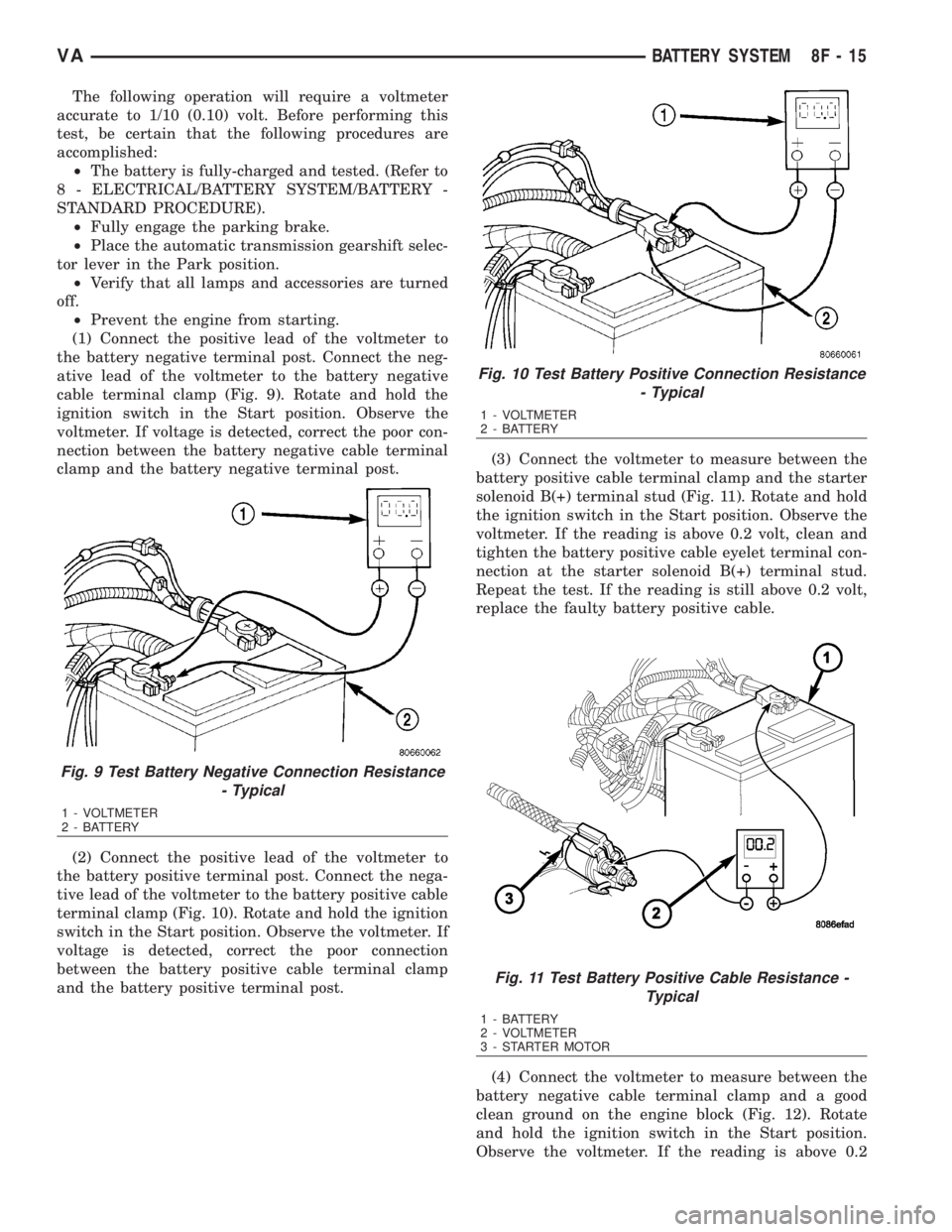
(1) Connect the positive lead of the voltmeter to
the battery negative terminal post. Connect the neg-
ative lead of the voltmeter to the battery negative
cable terminal clamp (Fig. 9). Rotate and hold the
ignition switch in the Start position. Observe the
voltmeter. If voltage is detected, correct the poor con-
nection between the battery negative cable terminal
clamp and the battery negative terminal post.
(2) Connect the positive lead of the voltmeter to
the battery positive terminal post. Connect the nega-
tive lead of the voltmeter to the battery positive cable
terminal clamp (Fig. 10). Rotate and hold the ignition
switch in the Start position. Observe the voltmeter. If
voltage is detected, correct the poor connection
between the battery positive cable terminal clamp
and the battery positive terminal post.(3) Connect the voltmeter to measure between the
battery positive cable terminal clamp and the starter
solenoid B(+) terminal stud (Fig. 11). Rotate and hold
the ignition switch in the Start position. Observe the
voltmeter. If the reading is above 0.2 volt, clean and
tighten the battery positive cable eyelet terminal con-
nection at the starter solenoid B(+) terminal stud.
Repeat the test. If the reading is still above 0.2 volt,
replace the faulty battery positive cable.
(4) Connect the voltmeter to measure between the
battery negative cable terminal clamp and a good
clean ground on the engine block (Fig. 12). Rotate
and hold the ignition switch in the Start position.
Observe the voltmeter. If the reading is above 0.2
Fig. 9 Test Battery Negative Connection Resistance
- Typical
1 - VOLTMETER
2 - BATTERY
Fig. 10 Test Battery Positive Connection Resistance
- Typical
1 - VOLTMETER
2 - BATTERY
Fig. 11 Test Battery Positive Cable Resistance -
Typical
1 - BATTERY
2 - VOLTMETER
3 - STARTER MOTOR
VABATTERY SYSTEM 8F - 15
Page 893 of 2305

STARTING SYSTEM
TABLE OF CONTENTS
page page
STARTING SYSTEM
DESCRIPTION.........................28
OPERATION...........................28
DIAGNOSIS AND TESTING - STARTING
SYSTEM............................29
SPECIFICATIONS
TORQUE - STARTER - DIESEL...........33
SPECIFICATIONS - STARTER MOTOR -
DIESEL.............................33STARTER MOTOR
DIAGNOSIS AND TESTING - STARTER
MOTOR .............................33
REMOVAL.............................34
INSTALLATION.........................35
STARTER MOTOR RELAY
DESCRIPTION.........................35
REMOVAL.............................35
INSTALLATION.........................36
STARTING SYSTEM
DESCRIPTION
The starting system consists of:
²Starter relay
²Starter motor (including an integral starter sole-
noid)
Other components to be considered as part of start-
ing system are:
²Battery
²Battery cables
²Ignition switch and key lock cylinder
²Park/neutral position switch (automatic trans-
mission)
²Wire harnesses and connections.
The Battery, Starting, and Charging systems oper-
ate in conjunction with one another, and must be
tested as a complete system. For correct operation of
starting/charging systems, all components used in
these 3 systems must perform within specifications.
When attempting to diagnose any of these systems, it
is important that you keep their interdependency in
mind.
The diagnostic procedures used in each of these
groups include the most basic conventional diagnostic
methods, to the more sophisticated On-Board Diag-
nostics (OBD) built into the Engine Control Module
(ECM). Use of an induction-type milliampere amme-
ter, volt/ohmmeter, battery charger, carbon pile rheo-
stat (load tester), and 12-volt test lamp may be
required.
Certain starting system components are monitored
by the ECM and may produce a Diagnostic Trouble
Code (DTC).
OPERATION
The starting system components form two separate
circuits. A high-amperage feed circuit that feeds the
starter motor high-amperage, and a low-amperagecontrol circuit that operates on less than 20 amperes.
The high-amperage feed circuit components include
the battery, the battery cables, the contact disc por-
tion of the starter solenoid, and the starter motor
itself. The low-amperage control circuit components
include the ignition switch, the park/neutral position
switch (automatic transmission), the starter relay,
the electromagnetic windings of the starter solenoid,
and the connecting wire harness components.
If the vehicle is equipped with an automatic trans-
mission, battery voltage is supplied through the low-
amperage control circuit to the coil battery terminal
of the starter relay when the ignition switch is
turned to the momentary Start position. The park/
neutral position switch is installed in series between
the starter relay coil ground terminal and ground.
This normally open switch prevents the starter relay
from being energized and the starter motor from
operating unless the automatic transmission gear
selector is in the Neutral or Park positions.
When the starter relay coil is energized, the nor-
mally open relay contacts close. The relay contacts
connect the relay common feed terminal to the relay
normally open terminal. The closed relay contacts
energize the starter solenoid coil windings.
The energized solenoid pull-in coil pulls in the sole-
noid plunger. The solenoid plunger pulls the shift
lever in the starter motor. This engages the starter
overrunning clutch and pinion gear with the starter
ring gear on the manual transmission flywheel or on
the automatic transmission torque converter or
torque converter drive plate.
As the solenoid plunger reaches the end of its
travel, the solenoid contact disc completes the high-
amperage starter feed circuit and energizes the sole-
noid plunger hold-in coil. Current now flows between
the solenoid battery terminal and the starter motor,
energizing the starter.
Once the engine starts, the overrunning clutch pro-
tects the starter motor from damage by allowing the
8F - 28 STARTING SYSTEMVA