2006 MERCEDES-BENZ SPRINTER starter
[x] Cancel search: starterPage 585 of 2305
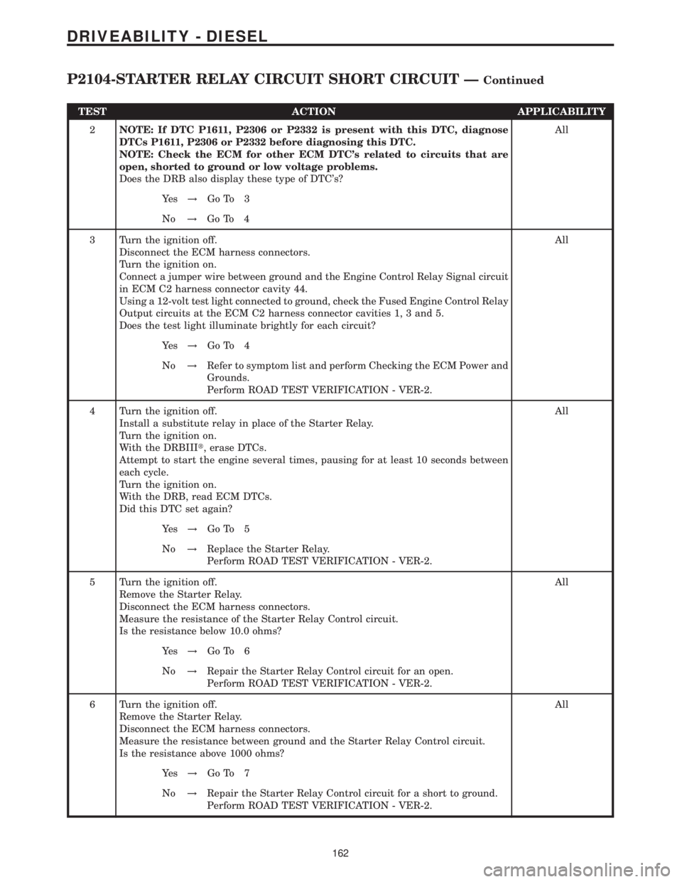
TEST ACTION APPLICABILITY
2NOTE: If DTC P1611, P2306 or P2332 is present with this DTC, diagnose
DTCs P1611, P2306 or P2332 before diagnosing this DTC.
NOTE: Check the ECM for other ECM DTC's related to circuits that are
open, shorted to ground or low voltage problems.
Does the DRB also display these type of DTC's?All
Ye s!Go To 3
No!Go To 4
3 Turn the ignition off.
Disconnect the ECM harness connectors.
Turn the ignition on.
Connect a jumper wire between ground and the Engine Control Relay Signal circuit
in ECM C2 harness connector cavity 44.
Using a 12-volt test light connected to ground, check the Fused Engine Control Relay
Output circuits at the ECM C2 harness connector cavities 1, 3 and 5.
Does the test light illuminate brightly for each circuit?All
Ye s!Go To 4
No!Refer to symptom list and perform Checking the ECM Power and
Grounds.
Perform ROAD TEST VERIFICATION - VER-2.
4 Turn the ignition off.
Install a substitute relay in place of the Starter Relay.
Turn the ignition on.
With the DRBIIIt, erase DTCs.
Attempt to start the engine several times, pausing for at least 10 seconds between
each cycle.
Turn the ignition on.
With the DRB, read ECM DTCs.
Did this DTC set again?All
Ye s!Go To 5
No!Replace the Starter Relay.
Perform ROAD TEST VERIFICATION - VER-2.
5 Turn the ignition off.
Remove the Starter Relay.
Disconnect the ECM harness connectors.
Measure the resistance of the Starter Relay Control circuit.
Is the resistance below 10.0 ohms?All
Ye s!Go To 6
No!Repair the Starter Relay Control circuit for an open.
Perform ROAD TEST VERIFICATION - VER-2.
6 Turn the ignition off.
Remove the Starter Relay.
Disconnect the ECM harness connectors.
Measure the resistance between ground and the Starter Relay Control circuit.
Is the resistance above 1000 ohms?All
Ye s!Go To 7
No!Repair the Starter Relay Control circuit for a short to ground.
Perform ROAD TEST VERIFICATION - VER-2.
162
DRIVEABILITY - DIESEL
P2104-STARTER RELAY CIRCUIT SHORT CIRCUIT ÐContinued
Page 586 of 2305
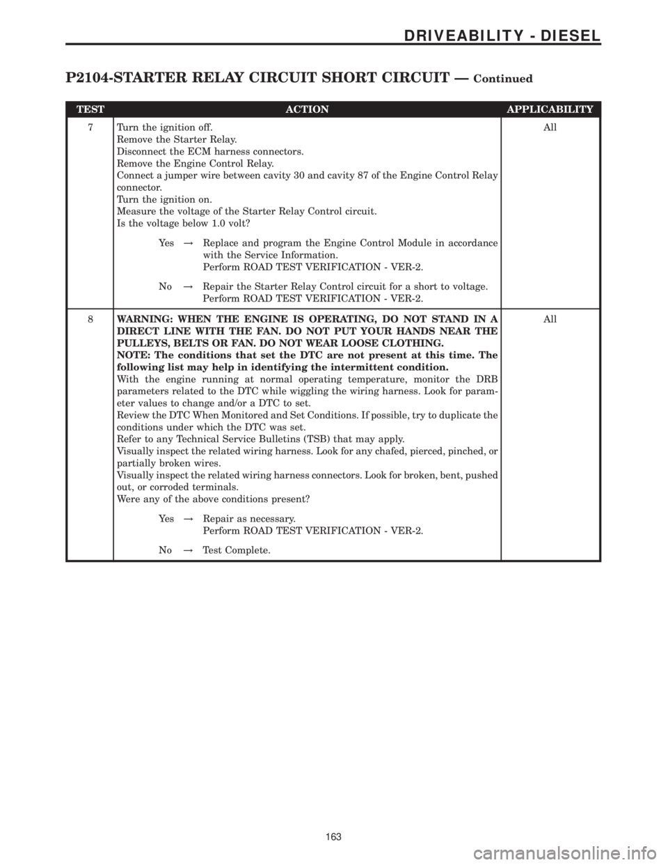
TEST ACTION APPLICABILITY
7 Turn the ignition off.
Remove the Starter Relay.
Disconnect the ECM harness connectors.
Remove the Engine Control Relay.
Connect a jumper wire between cavity 30 and cavity 87 of the Engine Control Relay
connector.
Turn the ignition on.
Measure the voltage of the Starter Relay Control circuit.
Is the voltage below 1.0 volt?All
Ye s!Replace and program the Engine Control Module in accordance
with the Service Information.
Perform ROAD TEST VERIFICATION - VER-2.
No!Repair the Starter Relay Control circuit for a short to voltage.
Perform ROAD TEST VERIFICATION - VER-2.
8WARNING: WHEN THE ENGINE IS OPERATING, DO NOT STAND IN A
DIRECT LINE WITH THE FAN. DO NOT PUT YOUR HANDS NEAR THE
PULLEYS, BELTS OR FAN. DO NOT WEAR LOOSE CLOTHING.
NOTE: The conditions that set the DTC are not present at this time. The
following list may help in identifying the intermittent condition.
With the engine running at normal operating temperature, monitor the DRB
parameters related to the DTC while wiggling the wiring harness. Look for param-
eter values to change and/or a DTC to set.
Review the DTC When Monitored and Set Conditions. If possible, try to duplicate the
conditions under which the DTC was set.
Refer to any Technical Service Bulletins (TSB) that may apply.
Visually inspect the related wiring harness. Look for any chafed, pierced, pinched, or
partially broken wires.
Visually inspect the related wiring harness connectors. Look for broken, bent, pushed
out, or corroded terminals.
Were any of the above conditions present?All
Ye s!Repair as necessary.
Perform ROAD TEST VERIFICATION - VER-2.
No!Test Complete.
163
DRIVEABILITY - DIESEL
P2104-STARTER RELAY CIRCUIT SHORT CIRCUIT ÐContinued
Page 637 of 2305
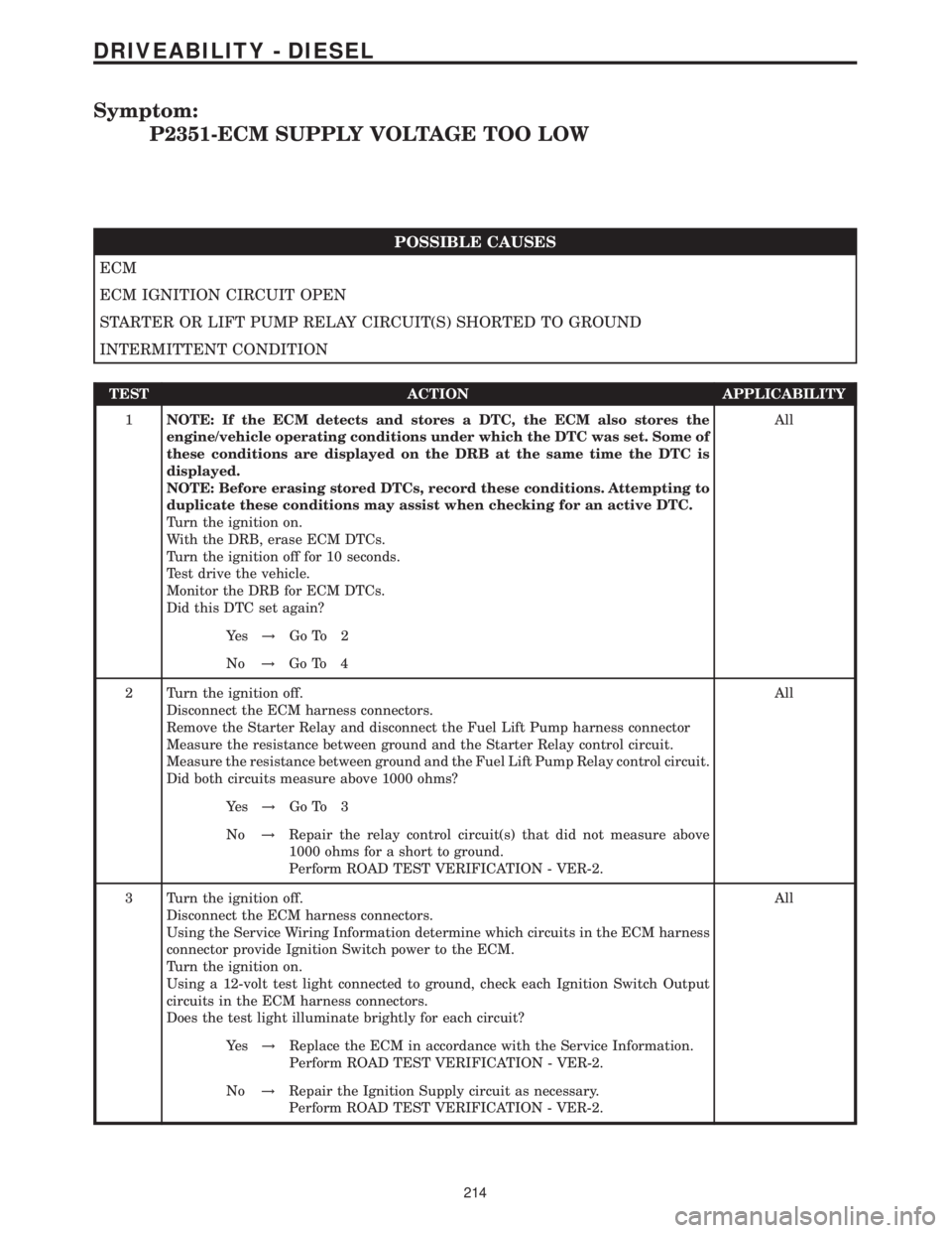
Symptom:
P2351-ECM SUPPLY VOLTAGE TOO LOW
POSSIBLE CAUSES
ECM
ECM IGNITION CIRCUIT OPEN
STARTER OR LIFT PUMP RELAY CIRCUIT(S) SHORTED TO GROUND
INTERMITTENT CONDITION
TEST ACTION APPLICABILITY
1NOTE: If the ECM detects and stores a DTC, the ECM also stores the
engine/vehicle operating conditions under which the DTC was set. Some of
these conditions are displayed on the DRB at the same time the DTC is
displayed.
NOTE: Before erasing stored DTCs, record these conditions. Attempting to
duplicate these conditions may assist when checking for an active DTC.
Turn the ignition on.
With the DRB, erase ECM DTCs.
Turn the ignition off for 10 seconds.
Test drive the vehicle.
Monitor the DRB for ECM DTCs.
Did this DTC set again?All
Ye s!Go To 2
No!Go To 4
2 Turn the ignition off.
Disconnect the ECM harness connectors.
Remove the Starter Relay and disconnect the Fuel Lift Pump harness connector
Measure the resistance between ground and the Starter Relay control circuit.
Measure the resistance between ground and the Fuel Lift Pump Relay control circuit.
Did both circuits measure above 1000 ohms?All
Ye s!Go To 3
No!Repair the relay control circuit(s) that did not measure above
1000 ohms for a short to ground.
Perform ROAD TEST VERIFICATION - VER-2.
3 Turn the ignition off.
Disconnect the ECM harness connectors.
Using the Service Wiring Information determine which circuits in the ECM harness
connector provide Ignition Switch power to the ECM.
Turn the ignition on.
Using a 12-volt test light connected to ground, check each Ignition Switch Output
circuits in the ECM harness connectors.
Does the test light illuminate brightly for each circuit?All
Ye s!Replace the ECM in accordance with the Service Information.
Perform ROAD TEST VERIFICATION - VER-2.
No!Repair the Ignition Supply circuit as necessary.
Perform ROAD TEST VERIFICATION - VER-2.
214
DRIVEABILITY - DIESEL
Page 659 of 2305
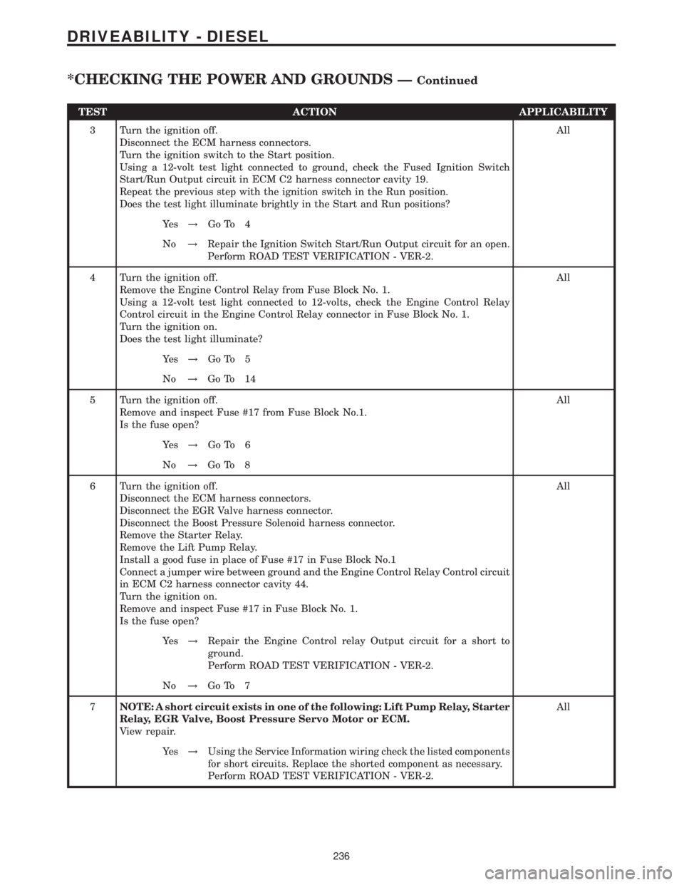
TEST ACTION APPLICABILITY
3 Turn the ignition off.
Disconnect the ECM harness connectors.
Turn the ignition switch to the Start position.
Using a 12-volt test light connected to ground, check the Fused Ignition Switch
Start/Run Output circuit in ECM C2 harness connector cavity 19.
Repeat the previous step with the ignition switch in the Run position.
Does the test light illuminate brightly in the Start and Run positions?All
Ye s!Go To 4
No!Repair the Ignition Switch Start/Run Output circuit for an open.
Perform ROAD TEST VERIFICATION - VER-2.
4 Turn the ignition off.
Remove the Engine Control Relay from Fuse Block No. 1.
Using a 12-volt test light connected to 12-volts, check the Engine Control Relay
Control circuit in the Engine Control Relay connector in Fuse Block No. 1.
Turn the ignition on.
Does the test light illuminate?All
Ye s!Go To 5
No!Go To 14
5 Turn the ignition off.
Remove and inspect Fuse #17 from Fuse Block No.1.
Is the fuse open?All
Ye s!Go To 6
No!Go To 8
6 Turn the ignition off.
Disconnect the ECM harness connectors.
Disconnect the EGR Valve harness connector.
Disconnect the Boost Pressure Solenoid harness connector.
Remove the Starter Relay.
Remove the Lift Pump Relay.
Install a good fuse in place of Fuse #17 in Fuse Block No.1
Connect a jumper wire between ground and the Engine Control Relay Control circuit
in ECM C2 harness connector cavity 44.
Turn the ignition on.
Remove and inspect Fuse #17 in Fuse Block No. 1.
Is the fuse open?All
Ye s!Repair the Engine Control relay Output circuit for a short to
ground.
Perform ROAD TEST VERIFICATION - VER-2.
No!Go To 7
7NOTE: A short circuit exists in one of the following: Lift Pump Relay, Starter
Relay, EGR Valve, Boost Pressure Servo Motor or ECM.
View repair.All
Ye s!Using the Service Information wiring check the listed components
for short circuits. Replace the shorted component as necessary.
Perform ROAD TEST VERIFICATION - VER-2.
236
DRIVEABILITY - DIESEL
*CHECKING THE POWER AND GROUNDS ÐContinued
Page 665 of 2305
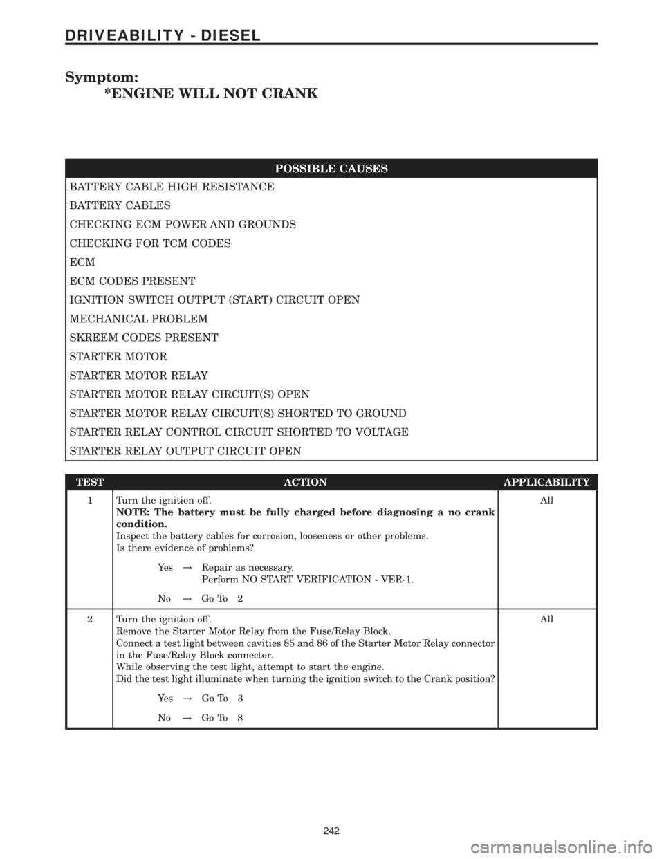
Symptom:
*ENGINE WILL NOT CRANK
POSSIBLE CAUSES
BATTERY CABLE HIGH RESISTANCE
BATTERY CABLES
CHECKING ECM POWER AND GROUNDS
CHECKING FOR TCM CODES
ECM
ECM CODES PRESENT
IGNITION SWITCH OUTPUT (START) CIRCUIT OPEN
MECHANICAL PROBLEM
SKREEM CODES PRESENT
STARTER MOTOR
STARTER MOTOR RELAY
STARTER MOTOR RELAY CIRCUIT(S) OPEN
STARTER MOTOR RELAY CIRCUIT(S) SHORTED TO GROUND
STARTER RELAY CONTROL CIRCUIT SHORTED TO VOLTAGE
STARTER RELAY OUTPUT CIRCUIT OPEN
TEST ACTION APPLICABILITY
1 Turn the ignition off.
NOTE: The battery must be fully charged before diagnosing a no crank
condition.
Inspect the battery cables for corrosion, looseness or other problems.
Is there evidence of problems?All
Ye s!Repair as necessary.
Perform NO START VERIFICATION - VER-1.
No!Go To 2
2 Turn the ignition off.
Remove the Starter Motor Relay from the Fuse/Relay Block.
Connect a test light between cavities 85 and 86 of the Starter Motor Relay connector
in the Fuse/Relay Block connector.
While observing the test light, attempt to start the engine.
Did the test light illuminate when turning the ignition switch to the Crank position?All
Ye s!Go To 3
No!Go To 8
242
DRIVEABILITY - DIESEL
Page 666 of 2305
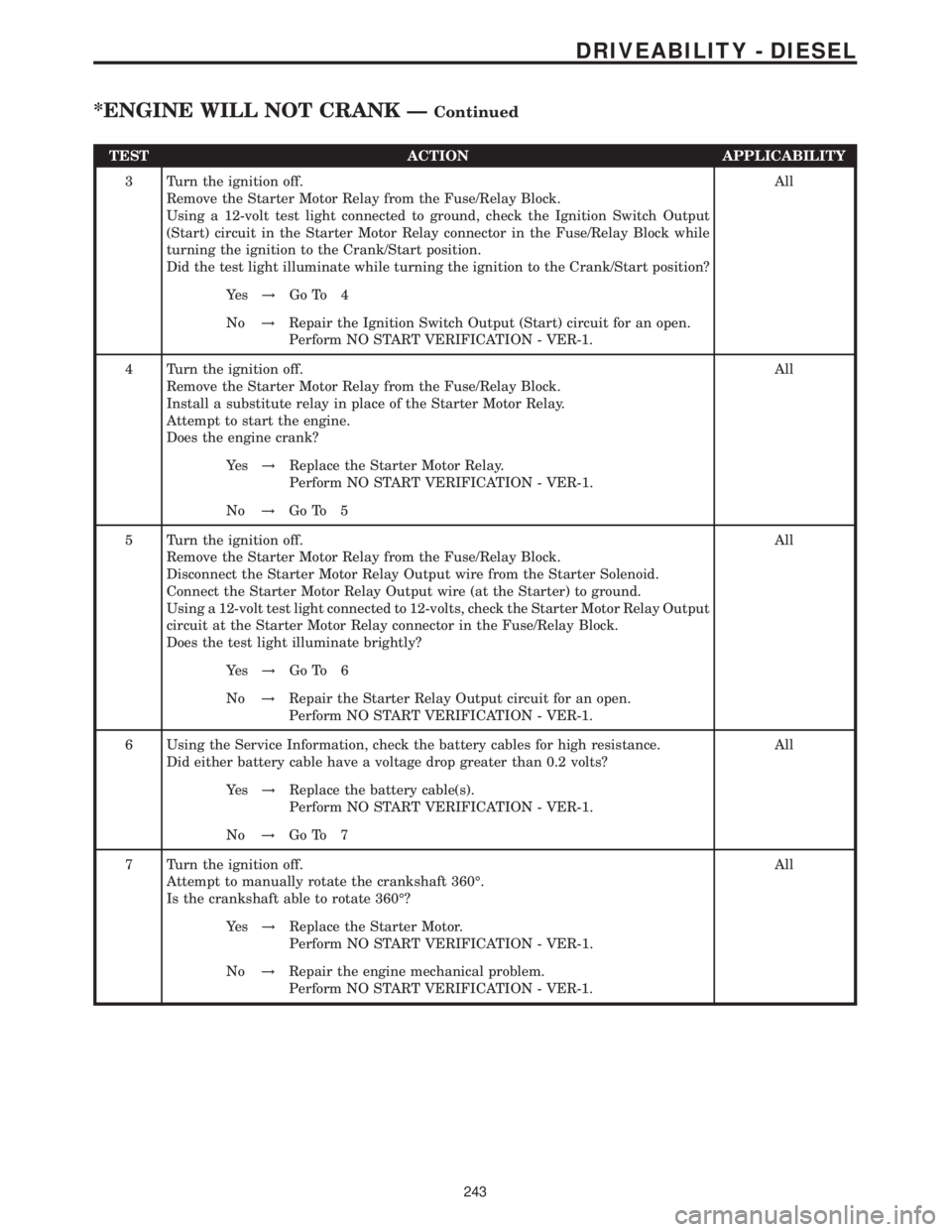
TEST ACTION APPLICABILITY
3 Turn the ignition off.
Remove the Starter Motor Relay from the Fuse/Relay Block.
Using a 12-volt test light connected to ground, check the Ignition Switch Output
(Start) circuit in the Starter Motor Relay connector in the Fuse/Relay Block while
turning the ignition to the Crank/Start position.
Did the test light illuminate while turning the ignition to the Crank/Start position?All
Ye s!Go To 4
No!Repair the Ignition Switch Output (Start) circuit for an open.
Perform NO START VERIFICATION - VER-1.
4 Turn the ignition off.
Remove the Starter Motor Relay from the Fuse/Relay Block.
Install a substitute relay in place of the Starter Motor Relay.
Attempt to start the engine.
Does the engine crank?All
Ye s!Replace the Starter Motor Relay.
Perform NO START VERIFICATION - VER-1.
No!Go To 5
5 Turn the ignition off.
Remove the Starter Motor Relay from the Fuse/Relay Block.
Disconnect the Starter Motor Relay Output wire from the Starter Solenoid.
Connect the Starter Motor Relay Output wire (at the Starter) to ground.
Using a 12-volt test light connected to 12-volts, check the Starter Motor Relay Output
circuit at the Starter Motor Relay connector in the Fuse/Relay Block.
Does the test light illuminate brightly?All
Ye s!Go To 6
No!Repair the Starter Relay Output circuit for an open.
Perform NO START VERIFICATION - VER-1.
6 Using the Service Information, check the battery cables for high resistance.
Did either battery cable have a voltage drop greater than 0.2 volts?All
Ye s!Replace the battery cable(s).
Perform NO START VERIFICATION - VER-1.
No!Go To 7
7 Turn the ignition off.
Attempt to manually rotate the crankshaft 360É.
Is the crankshaft able to rotate 360É?All
Ye s!Replace the Starter Motor.
Perform NO START VERIFICATION - VER-1.
No!Repair the engine mechanical problem.
Perform NO START VERIFICATION - VER-1.
243
DRIVEABILITY - DIESEL
*ENGINE WILL NOT CRANK ÐContinued
Page 667 of 2305
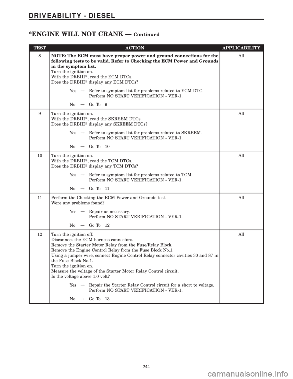
TEST ACTION APPLICABILITY
8NOTE: The ECM must have proper power and ground connections for the
following tests to be valid. Refer to Checking the ECM Power and Grounds
in the symptom list.
Turn the ignition on.
With the DRBIIIt, read the ECM DTCs.
Does the DRBIIItdisplay any ECM DTCs?All
Ye s!Refer to symptom list for problems related to ECM DTC.
Perform NO START VERIFICATION - VER-1.
No!Go To 9
9 Turn the ignition on.
With the DRBIIIt, read the SKREEM DTCs.
Does the DRBIIItdisplay any SKREEM DTCs?All
Ye s!Refer to symptom list for problems related to SKREEM.
Perform NO START VERIFICATION - VER-1.
No!Go To 10
10 Turn the ignition on.
With the DRBIIIt, read the TCM DTCs.
Does the DRBIIItdisplay any TCM DTCs?All
Ye s!Refer to symptom list for problems related to TCM.
Perform NO START VERIFICATION - VER-1.
No!Go To 11
11 Perform the Checking the ECM Power and Grounds test.
Were any problems found?All
Ye s!Repair as necessary.
Perform NO START VERIFICATION - VER-1.
No!Go To 12
12 Turn the ignition off.
Disconnect the ECM harness connectors.
Remove the Starter Motor Relay from the Fuse/Relay Block
Remove the Engine Control Relay from the Fuse Block No.1.
Using a jumper wire, connect Engine Control Relay connector cavities 30 and 87 in
the Fuse Block No.1.
Turn the ignition on.
Measure the voltage of the Starter Motor Relay Control circuit.
Is the voltage above 1.0 volt?All
Ye s!Repair the Starter Relay Control circuit for a short to voltage.
Perform NO START VERIFICATION - VER-1.
No!Go To 13
244
DRIVEABILITY - DIESEL
*ENGINE WILL NOT CRANK ÐContinued
Page 668 of 2305
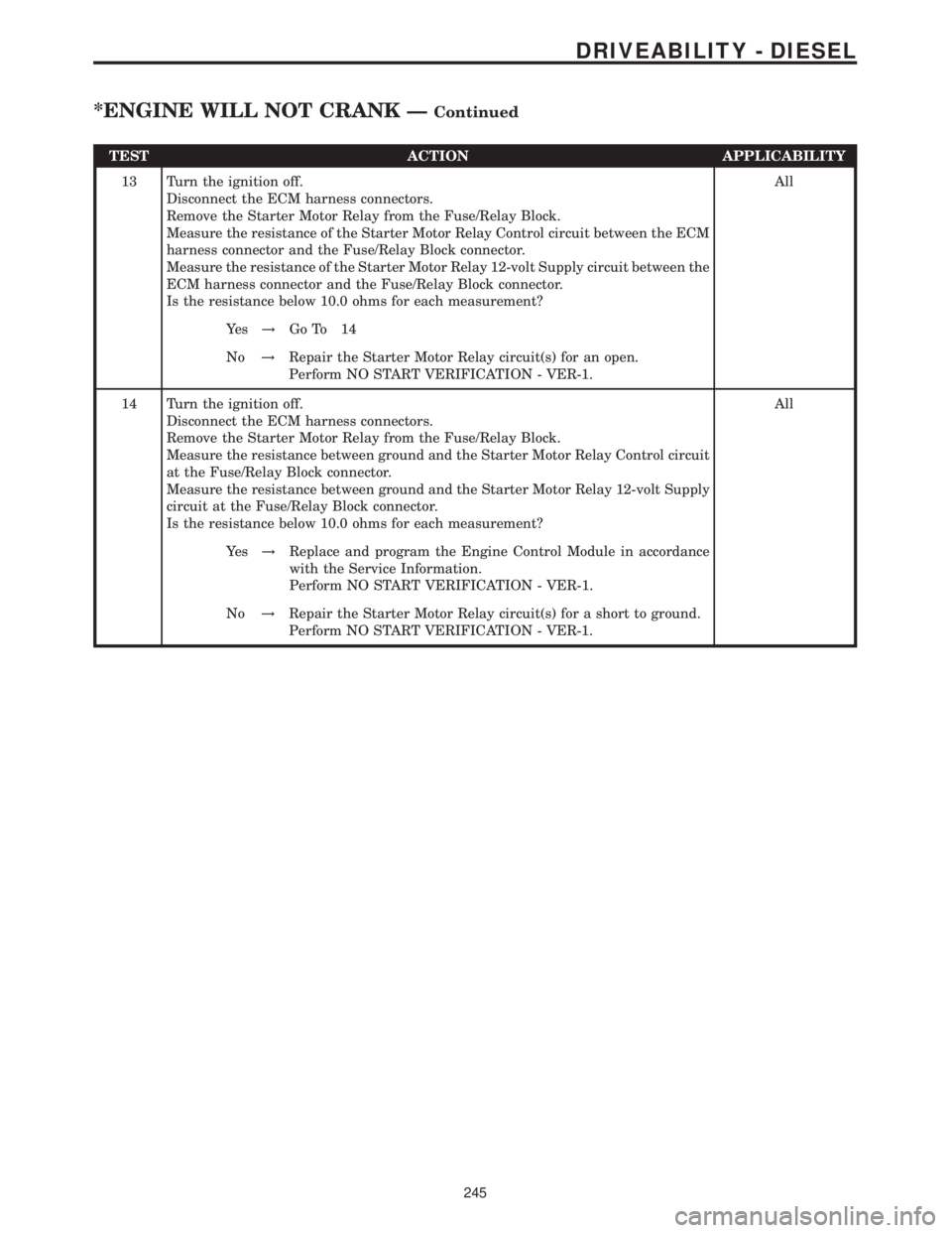
TEST ACTION APPLICABILITY
13 Turn the ignition off.
Disconnect the ECM harness connectors.
Remove the Starter Motor Relay from the Fuse/Relay Block.
Measure the resistance of the Starter Motor Relay Control circuit between the ECM
harness connector and the Fuse/Relay Block connector.
Measure the resistance of the Starter Motor Relay 12-volt Supply circuit between the
ECM harness connector and the Fuse/Relay Block connector.
Is the resistance below 10.0 ohms for each measurement?All
Ye s!Go To 14
No!Repair the Starter Motor Relay circuit(s) for an open.
Perform NO START VERIFICATION - VER-1.
14 Turn the ignition off.
Disconnect the ECM harness connectors.
Remove the Starter Motor Relay from the Fuse/Relay Block.
Measure the resistance between ground and the Starter Motor Relay Control circuit
at the Fuse/Relay Block connector.
Measure the resistance between ground and the Starter Motor Relay 12-volt Supply
circuit at the Fuse/Relay Block connector.
Is the resistance below 10.0 ohms for each measurement?All
Ye s!Replace and program the Engine Control Module in accordance
with the Service Information.
Perform NO START VERIFICATION - VER-1.
No!Repair the Starter Motor Relay circuit(s) for a short to ground.
Perform NO START VERIFICATION - VER-1.
245
DRIVEABILITY - DIESEL
*ENGINE WILL NOT CRANK ÐContinued