2006 MERCEDES-BENZ SPRINTER engine oil
[x] Cancel search: engine oilPage 859 of 2305

ECM Control Strategy The engine control module
is involved with a variety of functions such as: (Fig.
3)
²Individual injector activation
²Engine idle speed control to ensure smooth
engine idling independent of engine load
²Ride comfort function such as anti jerk control:
The CDI control module detects irregularities in
engine speed (resulting, for example, from load
changes or gear shift) from the signal supplied by the
crankshaft position sensor and reduces them by
adjusting the quantity injected into each of the cylin-
ders
²Constant RPM (high idle feature) for ambulance
vehicle bodies equipped with electrical appliances
²Starter control, immobilizer, cruise control, kick
down, air conditioner
²Maintenance computer ASSYST (optional)
²Glow plug for pre-heating, post heating and
intermittent heating
²Error code memory/diagnostics, communication
interface for diagnosis and handling the fault codes
²The maximum vehicle speed is programmable
from 19±82 m.p.h. The standard is 82 m.p.h.
Fig. 2 ECM
1 - MASS AIR FLOW SENSOR 8 - CHARGE AIR PRESSURE SENSOR
2 - TURBOCHARGER SERVO MOTOR 9 - CHARGE AIR TEMPERATURE SENSOR
3 - CAMSHAFT POSITION SENSOR 10 - COOLANT TEMPERATURE SENSOR
4 - ENGINE OIL SENSOR 11 - FUEL RAIL PRESSURE SENSOR
5 - CRANKSHAFT POSITION SENSOR 12 - FUEL TEMPERATURE SENSOR
6 - PRESSURE REGULATOR VALVE 13 - FUEL QUANTITY CONTROL VALVE
7 - EGR VALVE 14 - AIR INTAKE PRESSURE SENSOR
8E - 4 ELECTRONIC CONTROL MODULESVA
Page 883 of 2305
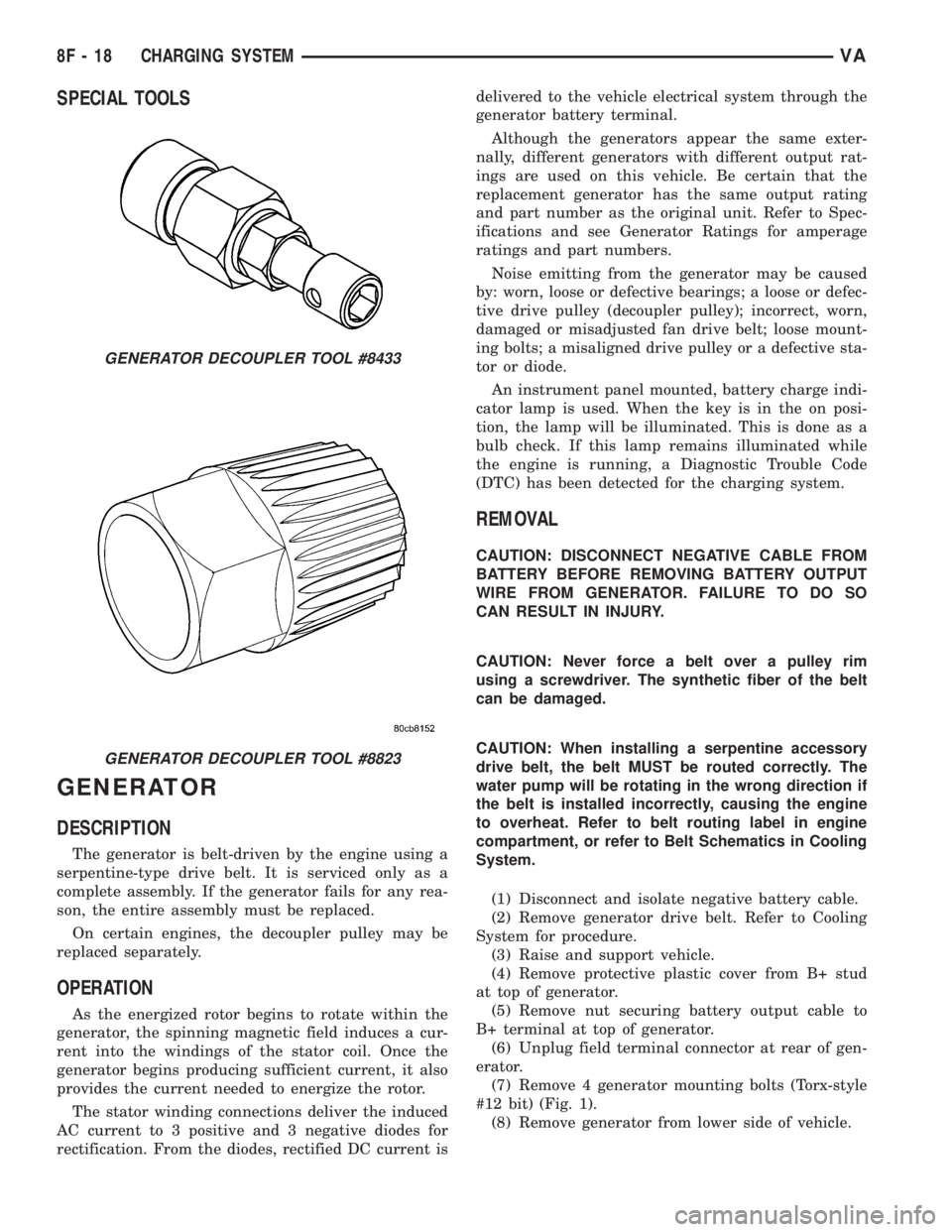
SPECIAL TOOLS
GENERATOR
DESCRIPTION
The generator is belt-driven by the engine using a
serpentine-type drive belt. It is serviced only as a
complete assembly. If the generator fails for any rea-
son, the entire assembly must be replaced.
On certain engines, the decoupler pulley may be
replaced separately.
OPERATION
As the energized rotor begins to rotate within the
generator, the spinning magnetic field induces a cur-
rent into the windings of the stator coil. Once the
generator begins producing sufficient current, it also
provides the current needed to energize the rotor.
The stator winding connections deliver the induced
AC current to 3 positive and 3 negative diodes for
rectification. From the diodes, rectified DC current isdelivered to the vehicle electrical system through the
generator battery terminal.
Although the generators appear the same exter-
nally, different generators with different output rat-
ings are used on this vehicle. Be certain that the
replacement generator has the same output rating
and part number as the original unit. Refer to Spec-
ifications and see Generator Ratings for amperage
ratings and part numbers.
Noise emitting from the generator may be caused
by: worn, loose or defective bearings; a loose or defec-
tive drive pulley (decoupler pulley); incorrect, worn,
damaged or misadjusted fan drive belt; loose mount-
ing bolts; a misaligned drive pulley or a defective sta-
tor or diode.
An instrument panel mounted, battery charge indi-
cator lamp is used. When the key is in the on posi-
tion, the lamp will be illuminated. This is done as a
bulb check. If this lamp remains illuminated while
the engine is running, a Diagnostic Trouble Code
(DTC) has been detected for the charging system.
REMOVAL
CAUTION: DISCONNECT NEGATIVE CABLE FROM
BATTERY BEFORE REMOVING BATTERY OUTPUT
WIRE FROM GENERATOR. FAILURE TO DO SO
CAN RESULT IN INJURY.
CAUTION: Never force a belt over a pulley rim
using a screwdriver. The synthetic fiber of the belt
can be damaged.
CAUTION: When installing a serpentine accessory
drive belt, the belt MUST be routed correctly. The
water pump will be rotating in the wrong direction if
the belt is installed incorrectly, causing the engine
to overheat. Refer to belt routing label in engine
compartment, or refer to Belt Schematics in Cooling
System.
(1) Disconnect and isolate negative battery cable.
(2) Remove generator drive belt. Refer to Cooling
System for procedure.
(3) Raise and support vehicle.
(4) Remove protective plastic cover from B+ stud
at top of generator.
(5) Remove nut securing battery output cable to
B+ terminal at top of generator.
(6) Unplug field terminal connector at rear of gen-
erator.
(7) Remove 4 generator mounting bolts (Torx-style
#12 bit) (Fig. 1).
(8) Remove generator from lower side of vehicle.
GENERATOR DECOUPLER TOOL #8433
GENERATOR DECOUPLER TOOL #8823
8F - 18 CHARGING SYSTEMVA
Page 893 of 2305

STARTING SYSTEM
TABLE OF CONTENTS
page page
STARTING SYSTEM
DESCRIPTION.........................28
OPERATION...........................28
DIAGNOSIS AND TESTING - STARTING
SYSTEM............................29
SPECIFICATIONS
TORQUE - STARTER - DIESEL...........33
SPECIFICATIONS - STARTER MOTOR -
DIESEL.............................33STARTER MOTOR
DIAGNOSIS AND TESTING - STARTER
MOTOR .............................33
REMOVAL.............................34
INSTALLATION.........................35
STARTER MOTOR RELAY
DESCRIPTION.........................35
REMOVAL.............................35
INSTALLATION.........................36
STARTING SYSTEM
DESCRIPTION
The starting system consists of:
²Starter relay
²Starter motor (including an integral starter sole-
noid)
Other components to be considered as part of start-
ing system are:
²Battery
²Battery cables
²Ignition switch and key lock cylinder
²Park/neutral position switch (automatic trans-
mission)
²Wire harnesses and connections.
The Battery, Starting, and Charging systems oper-
ate in conjunction with one another, and must be
tested as a complete system. For correct operation of
starting/charging systems, all components used in
these 3 systems must perform within specifications.
When attempting to diagnose any of these systems, it
is important that you keep their interdependency in
mind.
The diagnostic procedures used in each of these
groups include the most basic conventional diagnostic
methods, to the more sophisticated On-Board Diag-
nostics (OBD) built into the Engine Control Module
(ECM). Use of an induction-type milliampere amme-
ter, volt/ohmmeter, battery charger, carbon pile rheo-
stat (load tester), and 12-volt test lamp may be
required.
Certain starting system components are monitored
by the ECM and may produce a Diagnostic Trouble
Code (DTC).
OPERATION
The starting system components form two separate
circuits. A high-amperage feed circuit that feeds the
starter motor high-amperage, and a low-amperagecontrol circuit that operates on less than 20 amperes.
The high-amperage feed circuit components include
the battery, the battery cables, the contact disc por-
tion of the starter solenoid, and the starter motor
itself. The low-amperage control circuit components
include the ignition switch, the park/neutral position
switch (automatic transmission), the starter relay,
the electromagnetic windings of the starter solenoid,
and the connecting wire harness components.
If the vehicle is equipped with an automatic trans-
mission, battery voltage is supplied through the low-
amperage control circuit to the coil battery terminal
of the starter relay when the ignition switch is
turned to the momentary Start position. The park/
neutral position switch is installed in series between
the starter relay coil ground terminal and ground.
This normally open switch prevents the starter relay
from being energized and the starter motor from
operating unless the automatic transmission gear
selector is in the Neutral or Park positions.
When the starter relay coil is energized, the nor-
mally open relay contacts close. The relay contacts
connect the relay common feed terminal to the relay
normally open terminal. The closed relay contacts
energize the starter solenoid coil windings.
The energized solenoid pull-in coil pulls in the sole-
noid plunger. The solenoid plunger pulls the shift
lever in the starter motor. This engages the starter
overrunning clutch and pinion gear with the starter
ring gear on the manual transmission flywheel or on
the automatic transmission torque converter or
torque converter drive plate.
As the solenoid plunger reaches the end of its
travel, the solenoid contact disc completes the high-
amperage starter feed circuit and energizes the sole-
noid plunger hold-in coil. Current now flows between
the solenoid battery terminal and the starter motor,
energizing the starter.
Once the engine starts, the overrunning clutch pro-
tects the starter motor from damage by allowing the
8F - 28 STARTING SYSTEMVA
Page 894 of 2305
starter pinion gear to spin faster than the pinion
shaft. When the driver releases the ignition switch to
the On position, the starter relay coil is de-energized.
This causes the relay contacts to open. When the
relay contacts open, the starter solenoid plunger
hold-in coil is de-energized.
When the solenoid plunger hold-in coil is de-ener-
gized, the solenoid plunger return spring returns the
plunger to its relaxed position. This causes the con-
tact disc to open the starter feed circuit, and the shift
lever to disengage the overrunning clutch and pinion
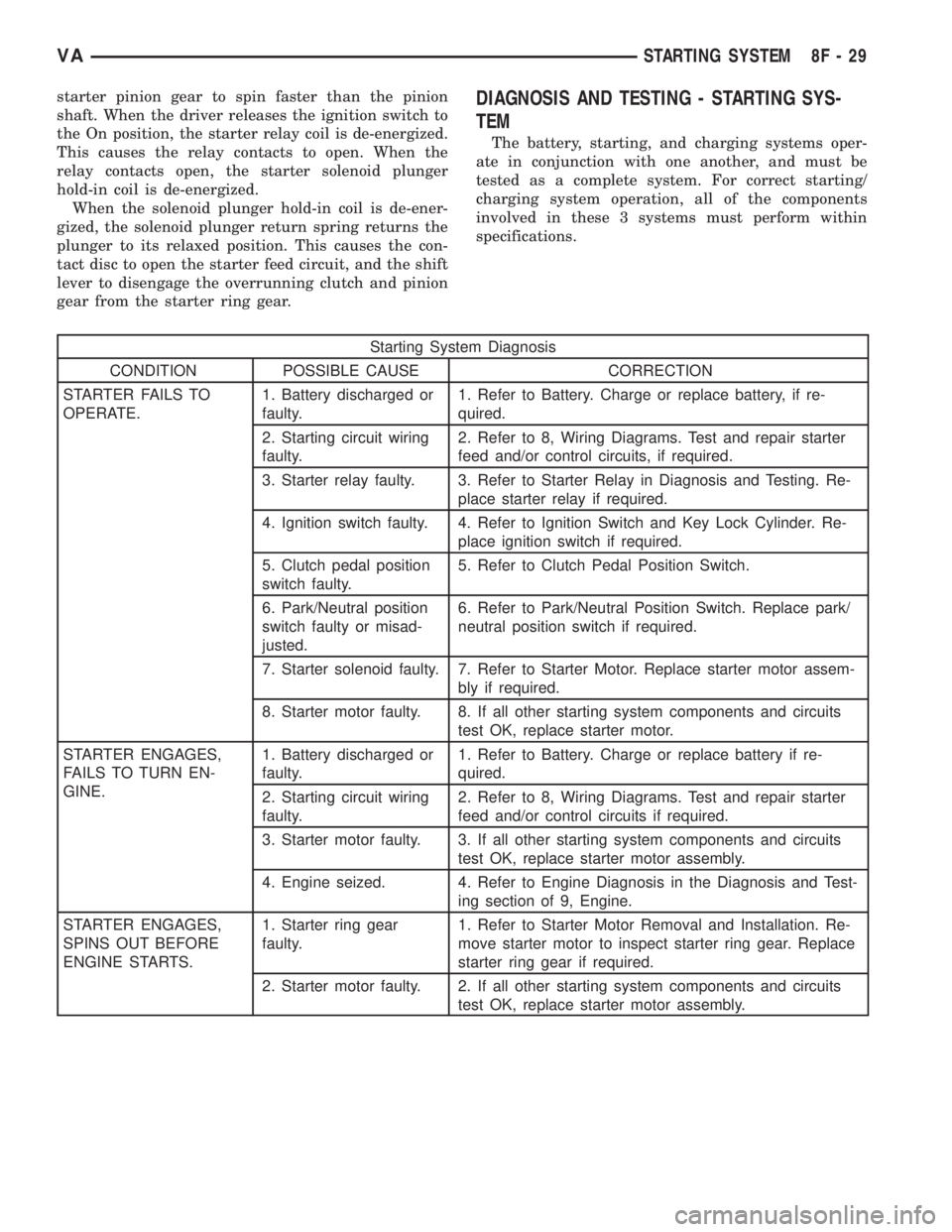
gear from the starter ring gear.DIAGNOSIS AND TESTING - STARTING SYS-
TEM
The battery, starting, and charging systems oper-
ate in conjunction with one another, and must be
tested as a complete system. For correct starting/
charging system operation, all of the components
involved in these 3 systems must perform within
specifications.
Starting System Diagnosis
CONDITION POSSIBLE CAUSE CORRECTION
STARTER FAILS TO
OPERATE.1. Battery discharged or
faulty.1. Refer to Battery. Charge or replace battery, if re-
quired.
2. Starting circuit wiring
faulty.2. Refer to 8, Wiring Diagrams. Test and repair starter
feed and/or control circuits, if required.
3. Starter relay faulty. 3. Refer to Starter Relay in Diagnosis and Testing. Re-
place starter relay if required.
4. Ignition switch faulty. 4. Refer to Ignition Switch and Key Lock Cylinder. Re-
place ignition switch if required.
5. Clutch pedal position
switch faulty.5. Refer to Clutch Pedal Position Switch.
6. Park/Neutral position
switch faulty or misad-
justed.6. Refer to Park/Neutral Position Switch. Replace park/
neutral position switch if required.
7. Starter solenoid faulty. 7. Refer to Starter Motor. Replace starter motor assem-
bly if required.
8. Starter motor faulty. 8. If all other starting system components and circuits
test OK, replace starter motor.
STARTER ENGAGES,
FAILS TO TURN EN-
GINE.1. Battery discharged or
faulty.1. Refer to Battery. Charge or replace battery if re-
quired.
2. Starting circuit wiring
faulty.2. Refer to 8, Wiring Diagrams. Test and repair starter
feed and/or control circuits if required.
3. Starter motor faulty. 3. If all other starting system components and circuits
test OK, replace starter motor assembly.
4. Engine seized. 4. Refer to Engine Diagnosis in the Diagnosis and Test-
ing section of 9, Engine.
STARTER ENGAGES,
SPINS OUT BEFORE
ENGINE STARTS.1. Starter ring gear
faulty.1. Refer to Starter Motor Removal and Installation. Re-
move starter motor to inspect starter ring gear. Replace
starter ring gear if required.
2. Starter motor faulty. 2. If all other starting system components and circuits
test OK, replace starter motor assembly.
VASTARTING SYSTEM 8F - 29
Page 898 of 2305
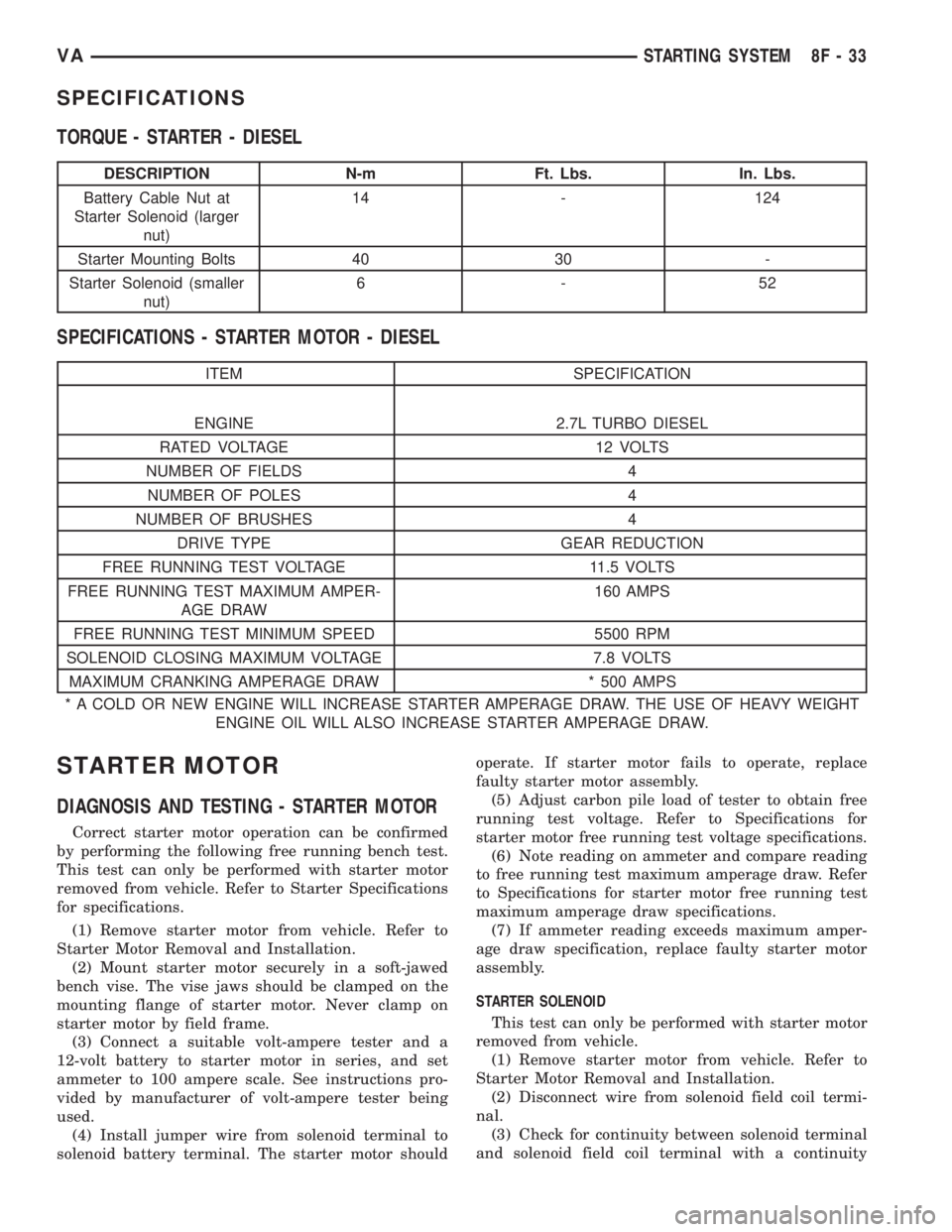
SPECIFICATIONS
TORQUE - STARTER - DIESEL
DESCRIPTION N-m Ft. Lbs. In. Lbs.
Battery Cable Nut at
Starter Solenoid (larger
nut)14 - 124
Starter Mounting Bolts 40 30 -
Starter Solenoid (smaller
nut)6-52
SPECIFICATIONS - STARTER MOTOR - DIESEL
ITEM SPECIFICATION
ENGINE 2.7L TURBO DIESEL
RATED VOLTAGE 12 VOLTS
NUMBER OF FIELDS 4
NUMBER OF POLES 4
NUMBER OF BRUSHES 4
DRIVE TYPE GEAR REDUCTION
FREE RUNNING TEST VOLTAGE 11.5 VOLTS
FREE RUNNING TEST MAXIMUM AMPER-
AGE DRAW160 AMPS
FREE RUNNING TEST MINIMUM SPEED 5500 RPM
SOLENOID CLOSING MAXIMUM VOLTAGE 7.8 VOLTS
MAXIMUM CRANKING AMPERAGE DRAW * 500 AMPS
* A COLD OR NEW ENGINE WILL INCREASE STARTER AMPERAGE DRAW. THE USE OF HEAVY WEIGHT
ENGINE OIL WILL ALSO INCREASE STARTER AMPERAGE DRAW.
STARTER MOTOR
DIAGNOSIS AND TESTING - STARTER MOTOR
Correct starter motor operation can be confirmed
by performing the following free running bench test.
This test can only be performed with starter motor
removed from vehicle. Refer to Starter Specifications
for specifications.
(1) Remove starter motor from vehicle. Refer to
Starter Motor Removal and Installation.
(2) Mount starter motor securely in a soft-jawed
bench vise. The vise jaws should be clamped on the
mounting flange of starter motor. Never clamp on
starter motor by field frame.
(3) Connect a suitable volt-ampere tester and a
12-volt battery to starter motor in series, and set
ammeter to 100 ampere scale. See instructions pro-
vided by manufacturer of volt-ampere tester being
used.
(4) Install jumper wire from solenoid terminal to
solenoid battery terminal. The starter motor shouldoperate. If starter motor fails to operate, replace
faulty starter motor assembly.
(5) Adjust carbon pile load of tester to obtain free
running test voltage. Refer to Specifications for
starter motor free running test voltage specifications.
(6) Note reading on ammeter and compare reading
to free running test maximum amperage draw. Refer
to Specifications for starter motor free running test
maximum amperage draw specifications.
(7) If ammeter reading exceeds maximum amper-
age draw specification, replace faulty starter motor
assembly.
STARTER SOLENOID
This test can only be performed with starter motor
removed from vehicle.
(1) Remove starter motor from vehicle. Refer to
Starter Motor Removal and Installation.
(2) Disconnect wire from solenoid field coil termi-
nal.
(3) Check for continuity between solenoid terminal
and solenoid field coil terminal with a continuity
VASTARTING SYSTEM 8F - 33
Page 899 of 2305
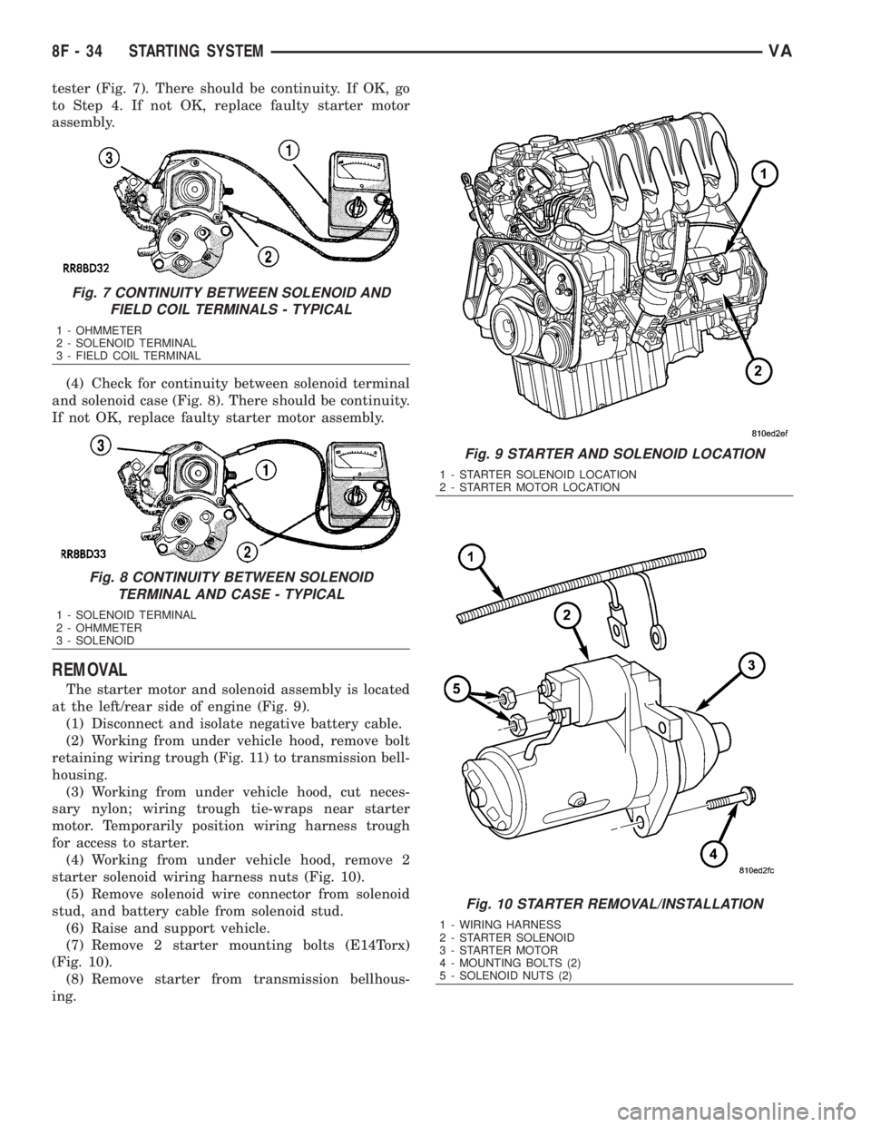
tester (Fig. 7). There should be continuity. If OK, go
to Step 4. If not OK, replace faulty starter motor
assembly.
(4) Check for continuity between solenoid terminal
and solenoid case (Fig. 8). There should be continuity.
If not OK, replace faulty starter motor assembly.
REMOVAL
The starter motor and solenoid assembly is located
at the left/rear side of engine (Fig. 9).
(1) Disconnect and isolate negative battery cable.
(2) Working from under vehicle hood, remove bolt
retaining wiring trough (Fig. 11) to transmission bell-
housing.
(3) Working from under vehicle hood, cut neces-
sary nylon; wiring trough tie-wraps near starter
motor. Temporarily position wiring harness trough
for access to starter.
(4) Working from under vehicle hood, remove 2
starter solenoid wiring harness nuts (Fig. 10).
(5) Remove solenoid wire connector from solenoid
stud, and battery cable from solenoid stud.
(6) Raise and support vehicle.
(7) Remove 2 starter mounting bolts (E14Torx)
(Fig. 10).
(8) Remove starter from transmission bellhous-
ing.
Fig. 7 CONTINUITY BETWEEN SOLENOID AND
FIELD COIL TERMINALS - TYPICAL
1 - OHMMETER
2 - SOLENOID TERMINAL
3 - FIELD COIL TERMINAL
Fig. 8 CONTINUITY BETWEEN SOLENOID
TERMINAL AND CASE - TYPICAL
1 - SOLENOID TERMINAL
2 - OHMMETER
3 - SOLENOID
Fig. 9 STARTER AND SOLENOID LOCATION
1 - STARTER SOLENOID LOCATION
2 - STARTER MOTOR LOCATION
Fig. 10 STARTER REMOVAL/INSTALLATION
1 - WIRING HARNESS
2 - STARTER SOLENOID
3 - STARTER MOTOR
4 - MOUNTING BOLTS (2)
5 - SOLENOID NUTS (2)
8F - 34 STARTING SYSTEMVA
Page 918 of 2305

IGNITION CONTROL
TABLE OF CONTENTS
page page
IGNITION CONTROL
OPERATION - GLOW PLUG................1
SPECIAL TOOLS........................1
GLOW PLUG
REMOVAL.............................1
INSTALLATION..........................1GLOW PLUG RELAY
DESCRIPTION..........................1
OPERATION............................2
DIAGNOSIS AND TESTING - GLOW PLUG
RELAYS..............................2
IGNITION CONTROL
OPERATION - GLOW PLUG
Pre - Glowing
With the key in the On position, the glow plug out-
put stage and the indicator lamp are actuated by the
ECM. The pre-heating time is calculated by the ECM
in line with the coolant temperature. The glow plug
output stage switches the current through the glow
plugs. The glow plug indicator lamp goes out after a
pre-glow period has elapsed. Component or cable fail-
ures in the pre-glow system are indicated by the glow
plug lamp and stored in the ECM.
Glow Output Stage
With the ignition key in the On position a signal is
transmitted from the ECM to the glow plug output
stager. If no data is exchanged with the ECM the
glow plug stage is terminated after two seconds. The
glow plug out put stage constantly signals the cur-
rent operating state (ON/OFF) and any system
faults. The following faults are recognized by the out
put stage and transmitted to the ECM:
²Open circuit in one or more of the glow plug
leads
²Short circuit in the glow plug circuit
²Out put stage fault or temperature related shut-
off
If a failure in the glow plug system occurs, the
glow plug indicator lamp will be illuminated only as
long as the fault is current. If the failure is no longer
present, the glow plug indicator lamp will be
switched off but a code will be stored in the ECM.
After Glow
Once the engine has started, the ECM determines
the after glow time depending on cooling tempera-
ture. During this time the glow plugs continue to be
actuated by the glow plug output stage. This results
in improved smooth running after a cold start and
improved warming up properties, elimination of blueexhaust after a cold start up and a more stable cold
starting speed.
If no signal is received from the coolant tempera-
ture sensor the signal from the oil sensor is used as a
substitute.
SPECIAL TOOLS
GLOW PLUG
REMOVAL
(1) Disconnect the negative battery cable.
(2) Remove the engine cover.
(3) Use special tool #9286 pliers to unplug the
glow plug wiring harness connector(s) at the glow
plug.
(4) Remove the glow plug(s) (Fig. 1).
INSTALLATION
(1) Screw glow plug(s) into cylinder head and
tighten to 12 N´m (115 lbs. in) (Fig. 1).
(2) Connect the glow plug wiring harness connec-
tor(s)
(3) Install the engine cover.
(4) Connect negative battery cable.
GLOW PLUG RELAY
DESCRIPTION
The glow plug relay supplies battery voltage to the
glow plug through a timed cycle that is related to
coolant temperature. The glow plug relay is located
under the battery. The purpose of a glow plug system
GLOW PLUG PLIERS
VAIGNITION CONTROL 8I - 1
Page 920 of 2305
INSTRUMENT CLUSTER
TABLE OF CONTENTS
page page
INSTRUMENT CLUSTER
DESCRIPTION..........................2
OPERATION............................5
DIAGNOSIS AND TESTING - INSTRUMENT
CLUSTER............................7
STANDARD PROCEDURE
CLUSTER PROGRAMMING...............7
REMOVAL.............................8
INSTALLATION..........................9
ABS INDICATOR
DESCRIPTION..........................9
OPERATION...........................10
ADR INDICATOR
DESCRIPTION.........................10
OPERATION...........................10
AIRBAG INDICATOR
DESCRIPTION.........................11
OPERATION...........................11
AMBIENT TEMPERATURE INDICATOR
DESCRIPTION.........................11
OPERATION...........................12
BRAKE INDICATOR
DESCRIPTION.........................12
OPERATION...........................12
BRAKE WEAR INDICATOR
DESCRIPTION.........................13
OPERATION...........................13
CHARGING INDICATOR
DESCRIPTION.........................14
OPERATION...........................14
CLOCK
DESCRIPTION.........................14
OPERATION...........................14
COOLANT LOW INDICATOR
DESCRIPTION.........................15
OPERATION...........................15
ENGINE TEMPERATURE GAUGE
DESCRIPTION.........................15
OPERATION...........................16
ESP INDICATOR
DESCRIPTION.........................16
OPERATION...........................16
FUEL FILTER CLOGGED INDICATOR
DESCRIPTION.........................17
OPERATION...........................17
FUEL GAUGE
DESCRIPTION.........................17
OPERATION...........................18
GEAR SELECTOR INDICATOR
DESCRIPTION.........................18
OPERATION...........................18HIGH BEAM INDICATOR
DESCRIPTION.........................19
OPERATION...........................19
LOW FUEL INDICATOR
DESCRIPTION.........................19
OPERATION...........................19
LOW OIL LEVEL INDICATOR
DESCRIPTION.........................20
OPERATION...........................20
MAINTENANCE INDICATOR
DESCRIPTION.........................20
OPERATION...........................21
MALFUNCTION INDICATOR LAMP (MIL)
DESCRIPTION.........................21
OPERATION...........................21
MULTI-FUNCTION INDICATOR
DESCRIPTION.........................22
OPERATION...........................22
ODOMETER
DESCRIPTION.........................22
OPERATION...........................23
PARK BRAKE INDICATOR
DESCRIPTION.........................23
OPERATION...........................24
SEATBELT INDICATOR
DESCRIPTION.........................24
OPERATION...........................24
SPEEDOMETER
DESCRIPTION.........................25
OPERATION...........................25
TACHOMETER
DESCRIPTION.........................25
OPERATION...........................25
TRACTION CONTROL INDICATOR
DESCRIPTION.........................26
OPERATION...........................26
TRACTION CONTROL MALFUNCTION
INDICATOR
DESCRIPTION.........................27
OPERATION...........................27
TURN SIGNAL INDICATOR
DESCRIPTION.........................27
OPERATION...........................27
WAIT-TO-START INDICATOR
DESCRIPTION.........................28
OPERATION...........................28
WASHER FLUID INDICATOR
DESCRIPTION.........................29
OPERATION...........................29
WATER-IN-FUEL INDICATOR
DESCRIPTION.........................29
OPERATION...........................29
VAINSTRUMENT CLUSTER 8J - 1