2006 MERCEDES-BENZ SPRINTER engine oil
[x] Cancel search: engine oilPage 639 of 2305
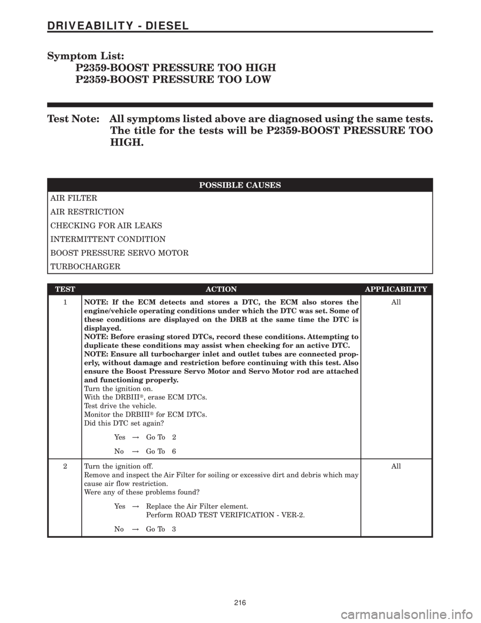
Symptom List:
P2359-BOOST PRESSURE TOO HIGH
P2359-BOOST PRESSURE TOO LOW
Test Note: All symptoms listed above are diagnosed using the same tests.
The title for the tests will be P2359-BOOST PRESSURE TOO
HIGH.
POSSIBLE CAUSES
AIR FILTER
AIR RESTRICTION
CHECKING FOR AIR LEAKS
INTERMITTENT CONDITION
BOOST PRESSURE SERVO MOTOR
TURBOCHARGER
TEST ACTION APPLICABILITY
1NOTE: If the ECM detects and stores a DTC, the ECM also stores the
engine/vehicle operating conditions under which the DTC was set. Some of
these conditions are displayed on the DRB at the same time the DTC is
displayed.
NOTE: Before erasing stored DTCs, record these conditions. Attempting to
duplicate these conditions may assist when checking for an active DTC.
NOTE: Ensure all turbocharger inlet and outlet tubes are connected prop-
erly, without damage and restriction before continuing with this test. Also
ensure the Boost Pressure Servo Motor and Servo Motor rod are attached
and functioning properly.
Turn the ignition on.
With the DRBIIIt, erase ECM DTCs.
Test drive the vehicle.
Monitor the DRBIIItfor ECM DTCs.
Did this DTC set again?All
Ye s!Go To 2
No!Go To 6
2 Turn the ignition off.
Remove and inspect the Air Filter for soiling or excessive dirt and debris which may
cause air flow restriction.
Were any of these problems found?All
Ye s!Replace the Air Filter element.
Perform ROAD TEST VERIFICATION - VER-2.
No!Go To 3
216
DRIVEABILITY - DIESEL
Page 670 of 2305
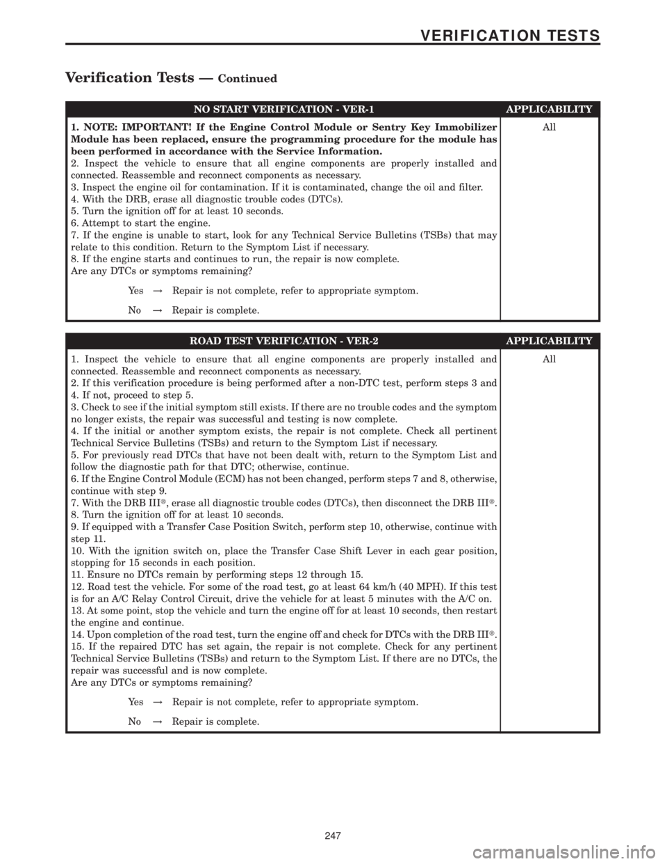
NO START VERIFICATION - VER-1 APPLICABILITY
1. NOTE: IMPORTANT! If the Engine Control Module or Sentry Key Immobilizer
Module has been replaced, ensure the programming procedure for the module has
been performed in accordance with the Service Information.
2. Inspect the vehicle to ensure that all engine components are properly installed and
connected. Reassemble and reconnect components as necessary.
3. Inspect the engine oil for contamination. If it is contaminated, change the oil and filter.
4. With the DRB, erase all diagnostic trouble codes (DTCs).
5. Turn the ignition off for at least 10 seconds.
6. Attempt to start the engine.
7. If the engine is unable to start, look for any Technical Service Bulletins (TSBs) that may
relate to this condition. Return to the Symptom List if necessary.
8. If the engine starts and continues to run, the repair is now complete.
Are any DTCs or symptoms remaining?All
Ye s!Repair is not complete, refer to appropriate symptom.
No!Repair is complete.
ROAD TEST VERIFICATION - VER-2 APPLICABILITY
1. Inspect the vehicle to ensure that all engine components are properly installed and
connected. Reassemble and reconnect components as necessary.
2. If this verification procedure is being performed after a non-DTC test, perform steps 3 and
4. If not, proceed to step 5.
3. Check to see if the initial symptom still exists. If there are no trouble codes and the symptom
no longer exists, the repair was successful and testing is now complete.
4. If the initial or another symptom exists, the repair is not complete. Check all pertinent
Technical Service Bulletins (TSBs) and return to the Symptom List if necessary.
5. For previously read DTCs that have not been dealt with, return to the Symptom List and
follow the diagnostic path for that DTC; otherwise, continue.
6. If the Engine Control Module (ECM) has not been changed, perform steps 7 and 8, otherwise,
continue with step 9.
7. With the DRB IIIt, erase all diagnostic trouble codes (DTCs), then disconnect the DRB IIIt.
8. Turn the ignition off for at least 10 seconds.
9. If equipped with a Transfer Case Position Switch, perform step 10, otherwise, continue with
step 11.
10. With the ignition switch on, place the Transfer Case Shift Lever in each gear position,
stopping for 15 seconds in each position.
11. Ensure no DTCs remain by performing steps 12 through 15.
12. Road test the vehicle. For some of the road test, go at least 64 km/h (40 MPH). If this test
is for an A/C Relay Control Circuit, drive the vehicle for at least 5 minutes with the A/C on.
13. At some point, stop the vehicle and turn the engine off for at least 10 seconds, then restart
the engine and continue.
14. Upon completion of the road test, turn the engine off and check for DTCs with the DRB IIIt.
15. If the repaired DTC has set again, the repair is not complete. Check for any pertinent
Technical Service Bulletins (TSBs) and return to the Symptom List. If there are no DTCs, the
repair was successful and is now complete.
Are any DTCs or symptoms remaining?All
Ye s!Repair is not complete, refer to appropriate symptom.
No!Repair is complete.
247
VERIFICATION TESTS
Verification Tests ÐContinued
Page 682 of 2305

ENGINE CONTROL MODULE C1 (OBD)CAV CIRCUIT FUNCTION
1 16BL FUEL INJECTOR NO. 1 HIGH-SIDE CONTROL
2 16BL/WT FUEL INJECTOR NO. 4 HIGH-SIDE CONTROL
3 16DG FUEL INJECTOR NO. 3 HIGH-SIDE CONTROL
4 20RD/WT FUEL PRESSURE SOLENOID 12 VOLT SUPPLY
8 18BL/GY FUEL TEMPERATURE SENSOR SIGNAL
10 20RD/YL ENGINE OIL SENSOR 5 VOLT SUPPLY
11 20GY/BL ENGINE OIL SENSOR SIGNAL
12 20BR/RD INTAKE PRESSURE SENSOR GROUND
13 20VT/DG INTAKE PRESSURE SENSOR SIGNAL
14 20BR/DG CAMSHAFT POSITION SENSOR GROUND
15 20DG/BK O2 1/1 PUMP CELL SIGNAL
20 18BK/YL WATER IN FUEL SENSOR SIGNAL
21 18BK/RD CRANKCASE HEATER SIGNAL
25 16BK FUEL INJECTOR NO. 2 HIGH-SIDE CONTROL
26 16BK/WT FUEL INJECTOR NO. 5 HIGH-SIDE CONTROL
28 18RD/BK FUEL QUANTITY SOLENOID 12 VOLT SUPPLY
31 20YL/BL MASS AIR FLOW SENSOR GROUND
32 18DG/BK FUEL TEMPERATURE SENSOR GROUND
35 20BR/BK SENSOR GROUND
36 20VT/RD INTAKE PRESSURE SENSOR 5 VOLT SUPPLY
37 20RD/BL CAMSHAFT POSITION SENSOR 5 VOLT SUPPLY
38 20YL/GY CAMSHAFT POSITION SENSOR SIGNAL
39 20GY O2 1/1 SENSOR CELL SIGNAL
40 20GY/WT O2 1/1 VIRTUAL GROUND
49 16BK/VT FUEL INJECTOR NO. 4 LOW-SIDE CONTROL
50 16BK/DG FUEL INJECTOR NO. 3 LOW-SIDE CONTROL
51 16BK/YL FUEL INJECTOR NO. 5 LOW-SIDE CONTROL
52 20BK/WT FUEL PRESSURE SOLENOID CONTROL
55 18BR WATER IN FUEL SENSOR GROUND
56 20BR/WT ENGINE COOLANT TEMPERATURE SENSOR GROUND
57 20DG/RD ENGINE COOLANT TEMPERATURE SENSOR SIGNAL
59 20DG/VT FUEL PRESSURE SENSOR SIGNAL
61 20BR/VT MASS AIR FLOW SENSOR 5 VOLT SUPPLY
62 20DG/YL O2 1/1 PUMP CELL CONTROL
72 20GY/BL O2 1/1 HEATER CONTROL
73 16BK/RD FUEL INJECTOR NO. 1 LOW-SIDE CONTROL
74 16BK/BL FUEL INJECTOR NO. 2 LOW-SIDE CONTROL
76 18BR/YL FUEL QUANTITY SOLENOID CONTROL
79 18BR/RD WATER IN FUEL SENSOR 12 VOLT SUPPLY
84 20BR/GY FUEL PRESSURE SENSOR GROUND
85 20YL/DG MASS AIR FLOW SENSOR SIGNAL
86 20RD/DG FUEL PRESSURE SENSOR 5 VOLT SUPPLY
87 20DG/WT CRANKSHAFT POSITION SENSOR SIGNAL NO. 1
88 20DG CRANKSHAFT POSITION SENSOR SIGNAL NO. 2
90 20DG/WT EGR VALVE CONTROL
91 18BK/BR CRANKCASE HEATER GROUND
93 16YL/DG BOOST PRESSURE SERVOMOTOR CONTROL
C
O
N
N
E
C
T
O
R
P
I
N
O
U
T
S
259
CONNECTOR PINOUTS
Page 684 of 2305

ENGINE OIL SENSOR - BLACKCAV CIRCUIT FUNCTION
1 20GY/BL ENGINE OIL SENSOR SIGNAL
2 20BR/BK SENSOR GROUND
3 20RD/YL ENGINE OIL SENSOR 5 VOLT SUPPLY
FUEL INJECTOR NO. 1 - BLACKCAV CIRCUIT FUNCTION
1 14BK/BL (EXCEPT OBD) FUEL INJECTOR NO. 1 CONTROL
1 16BK/RD (OBD) FUEL INJECTOR NO. 1 LOW-SIDE CONTROL
2 14BK (EXCEPT OBD) COMMON INJECTOR DRIVER NO. 1
2 16BL (OBD) FUEL INJECTOR NO. 1 HIGH-SIDE CONTROL
FUEL INJECTOR NO. 2 - BLACKCAV CIRCUIT FUNCTION
1 14BK/VT (EXCEPT OBD) FUEL INJECTOR NO. 2 CONTROL
1 16BK/BL (OBD) FUEL INJECTOR NO. 2 LOW-SIDE CONTROL
2 14BL (EXCEPT OBD) COMMON INJECTOR DRIVER NO. 2
2 16BK (OBD) FUEL INJECTOR NO. 2 HIGH-SIDE CONTROL
FUEL INJECTOR NO. 3 - BLACKCAV CIRCUIT FUNCTION
1 14BK/RD (EXCEPT OBD) FUEL INJECTOR NO. 3 CONTROL
1 16BK/DG (OBD) FUEL INJECTOR NO. 3 LOW-SIDE CONTROL
2 14BK (EXCEPT OBD) COMMON INJECTOR DRIVER NO. 1
2 16DG (OBD) FUEL INJECTOR NO. 3 HIGH-SIDE CONTROL
C
O
N
N
E
C
T
O
R
P
I
N
O
U
T
S
261
CONNECTOR PINOUTS
Page 708 of 2305
FASTENER IDENTIFICATION
DESCRIPTION
The SAE bolt strength grades range from grade 2
to grade 8. The higher the grade number, the greater
the bolt strength. Identification is determined by the
line marks on the top of each bolt head. The actual
bolt strength grade corresponds to the number of line
marks plus 2. The most commonly used metric bolt
strength classes are 9.8 and 10.9. The metric
strength class identification number is imprinted on
the head of the bolt. The higher the class number,
the greater the bolt strength. Some metric nuts are
imprinted with a single-digit strength class on the
nut face. Refer to the Fastener Identification and
Fastener Strength Charts (Fig. 2) and (Fig. 3).
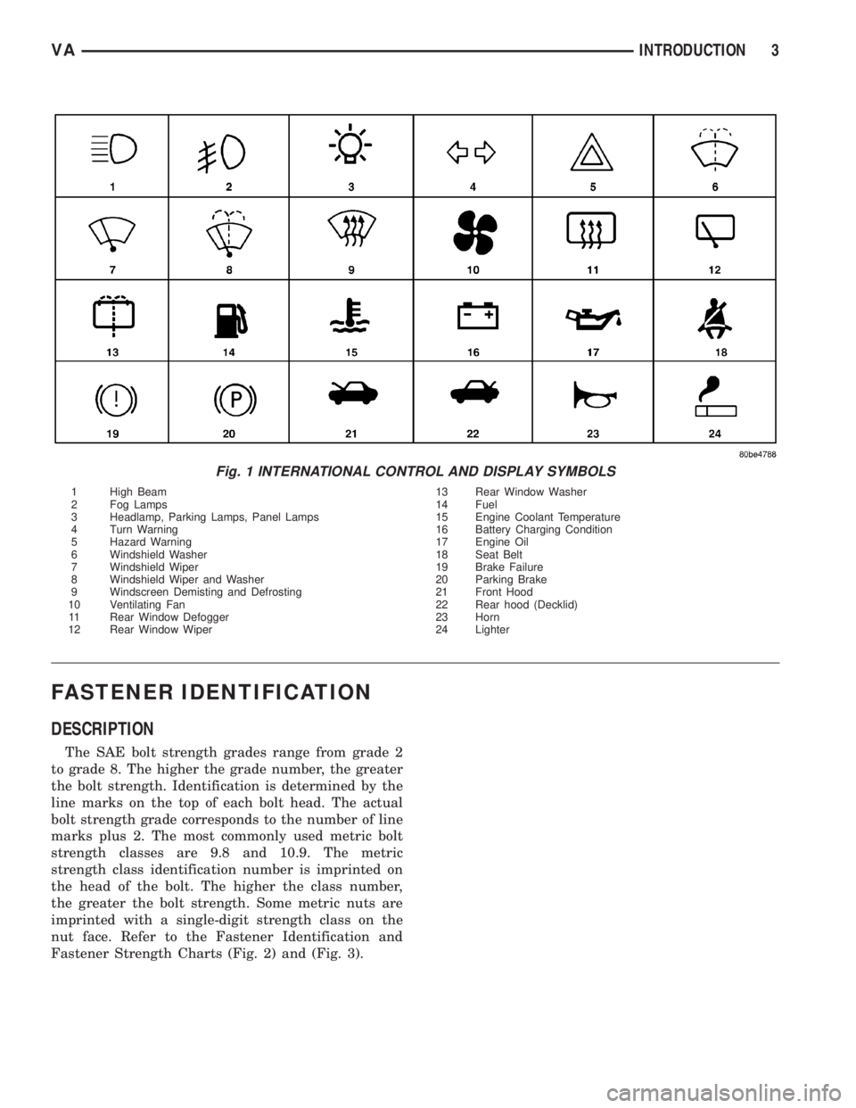
Fig. 1 INTERNATIONAL CONTROL AND DISPLAY SYMBOLS
1 High Beam 13 Rear Window Washer
2 Fog Lamps 14 Fuel
3 Headlamp, Parking Lamps, Panel Lamps 15 Engine Coolant Temperature
4 Turn Warning 16 Battery Charging Condition
5 Hazard Warning 17 Engine Oil
6 Windshield Washer 18 Seat Belt
7 Windshield Wiper 19 Brake Failure
8 Windshield Wiper and Washer 20 Parking Brake
9 Windscreen Demisting and Defrosting 21 Front Hood
10 Ventilating Fan 22 Rear hood (Decklid)
11 Rear Window Defogger 23 Horn
12 Rear Window Wiper 24 Lighter
VAINTRODUCTION 3
Page 716 of 2305
LUBRICATION & MAINTENANCE
TABLE OF CONTENTS
page page
FLUID TYPES
DESCRIPTION
PARTS AND LUBRICANT
RECOMMENDATIONS...................1
AUTOMATIC TRANSMISSION FLUID - NAG1 . 1
AXLE FLUID..........................2
BRAKE FLUID.........................2
HOAT COOLANT.......................2
ENGINE OIL - DIESEL ENGINES...........3
FUEL REQUIREMENTS - DIESEL ENGINE . . . 4
POWER STEERING FLUID...............5
OPERATION - AUTOMATIC TRANSMISSION
FLUID...............................5
FLUID CAPACITIES
SPECIFICATIONS - FLUID CAPACITIES.......5FLUID FILL/CHECK LOCATIONS
INSPECTION - FLUID FILL/CHECK
LOCATIONS..........................5
HOISTING
STANDARD PROCEDURE - HOISTING........5
JUMP STARTING
STANDARD PROCEDURE - JUMP STARTING . . 6
TOWING
STANDARD PROCEDURE - TOWING.........7
MAINTENANCE SCHEDULES
DESCRIPTION..........................8
INTERNATIONAL SYMBOLS
DESCRIPTION..........................9
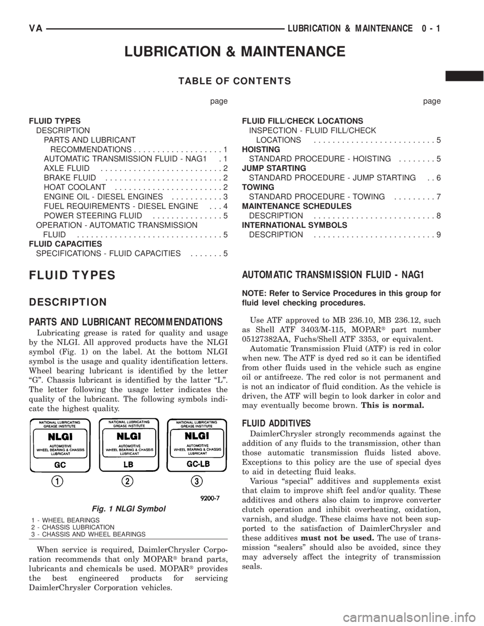
FLUID TYPES
DESCRIPTION
PARTS AND LUBRICANT RECOMMENDATIONS
Lubricating grease is rated for quality and usage
by the NLGI. All approved products have the NLGI
symbol (Fig. 1) on the label. At the bottom NLGI
symbol is the usage and quality identification letters.
Wheel bearing lubricant is identified by the letter
ªGº. Chassis lubricant is identified by the latter ªLº.
The letter following the usage letter indicates the
quality of the lubricant. The following symbols indi-
cate the highest quality.
When service is required, DaimlerChrysler Corpo-
ration recommends that only MOPARtbrand parts,
lubricants and chemicals be used. MOPARtprovides
the best engineered products for servicing
DaimlerChrysler Corporation vehicles.
AUTOMATIC TRANSMISSION FLUID - NAG1
NOTE: Refer to Service Procedures in this group for
fluid level checking procedures.
Use ATF approved to MB 236.10, MB 236.12, such
as Shell ATF 3403/M-115, MOPARtpart number
05127382AA, Fuchs/Shell ATF 3353, or equivalent.
Automatic Transmission Fluid (ATF) is red in color
when new. The ATF is dyed red so it can be identified
from other fluids used in the vehicle such as engine
oil or antifreeze. The red color is not permanent and
is not an indicator of fluid condition. As the vehicle is
driven, the ATF will begin to look darker in color and
may eventually become brown.This is normal.
FLUID ADDITIVES
DaimlerChrysler strongly recommends against the
addition of any fluids to the transmission, other than
those automatic transmission fluids listed above.
Exceptions to this policy are the use of special dyes
to aid in detecting fluid leaks.
Various ªspecialº additives and supplements exist
that claim to improve shift feel and/or quality. These
additives and others also claim to improve converter
clutch operation and inhibit overheating, oxidation,
varnish, and sludge. These claims have not been sup-
ported to the satisfaction of DaimlerChrysler and
these additivesmust not be used.The use of trans-
mission ªsealersº should also be avoided, since they
may adversely affect the integrity of transmission
seals.
Fig. 1 NLGI Symbol
1 - WHEEL BEARINGS
2 - CHASSIS LUBRICATION
3 - CHASSIS AND WHEEL BEARINGS
VALUBRICATION & MAINTENANCE 0 - 1
Page 717 of 2305
AXLE FLUID
Use oils approved to MB 235.0 or 235.6, such as
Shell Spirax MB90, Caltex Hypoid LD, or MOPARt
part number 4874469, or equivalent. An API GL-5/
MIL-2105-E SAE 90 Hypoid Gear Oil may be substi-
tuted. Reduced axle durability may result if an
unapproved product is used.
BRAKE FLUID
Use brake fluid approved to MB 331.0, such as
Intac B026D, MOPARtBrake & Clutch Fluid, part
number 04549625AC, or equivalent. If the approved
product is not available, use a DOT 4 brake fluid:
minimum dry boiling point (ERBP) 500ÉF, minimum
wet boiling point (WERBP) 356ÉF, maximum viscos-
ity 1500 mm
2/s, conforming to FMVSS 116 and ISO
4925.
HOAT COOLANT
WARNING: ANTIFREEZE IS AN ETHYLENE-GLYCOL
BASE COOLANT AND IS HARMFUL IF SWAL-
LOWED OR INHALED. IF SWALLOWED, DRINK
TWO GLASSES OF WATER AND INDUCE VOMIT-
ING. IF INHALED, MOVE TO FRESH AIR AREA.
SEEK MEDICAL ATTENTION IMMEDIATELY. DO NOT
STORE IN OPEN OR UNMARKED CONTAINERS.
WASH SKIN AND CLOTHING THOROUGHLY AFTER
COMING IN CONTACT WITH ETHYLENE-GLYCOL.
KEEP OUT OF REACH OF CHILDREN. DISPOSE OF
GLYCOL BASE COOLANT PROPERLY, CONTACT
YOUR DEALER OR GOVERNMENT AGENCY FOR
LOCATION OF COLLECTION CENTER IN YOUR
AREA. DO NOT OPEN A COOLING SYSTEM WHEN
THE ENGINE IS AT OPERATING TEMPERATURE OR
HOT UNDER PRESSURE, PERSONAL INJURY CAN
RESULT. AVOID RADIATOR COOLING FAN WHEN
ENGINE COMPARTMENT RELATED SERVICE IS
PERFORMED, PERSONAL INJURY CAN RESULT.
CAUTION: Use of Propylene-Glycol based coolants
is not recommended, as they provide less freeze
protection and less corrosion protection.
The cooling system is designed around the coolant.
The coolant must accept heat from engine metal, in
the cylinder head area near the exhaust valves and
engine block. Then coolant carries the heat to the
radiator where the tube/fin radiator can transfer the
heat to the air.
The use of aluminum cylinder blocks, cylinder
heads, and water pumps requires special corrosion
protection. Use coolant approved to MB 325.0, such
as EURO Peak Coolant/Anti-freeze (OLD WORLD
INDUSTRIES), Zerex G05 or G48 (The Valvoline
Company), Glysantin G05 (BASF AG), MOPARtpart
number 05066386AA, or an equivalent Extended LifeCoolant with the HOAT inhibitor system. This cool-
ant offers the best engine cooling without corrosion
when mixed with 50% anti-freeze and 50% distilled
water to obtain a freeze point of -37ÉC (-34ÉF). If it
loses color or becomes contaminated, drain, flush,
and replace with fresh properly mixed coolant solu-
tion.
CAUTION: This coolant may not be mixed with any
other type of antifreeze. Mixing of coolants other
than specified (non-HOAT), may result in engine
damage that may not be covered under the new
vehicle warranty, and decreased corrosion protec-
tion.
CAUTION: Do not use coolant additives that are
claimed to improve engine cooling.
COOLANT PERFORMANCE
The required ethylene-glycol (antifreeze) and water
mixture depends upon climate and vehicle operating
conditions. The coolant performance of various mix-
tures follows:
Pure Water-Water can absorb more heat than a
mixture of water and ethylene-glycol. This is for pur-
pose of heat transfer only. Water also freezes at a
higher temperature and allows corrosion.
100 percent Ethylene-Glycol-The corrosion
inhibiting additives in ethylene-glycol need the pres-
ence of water to dissolve. Without water, additives
form deposits in system. These act as insulation
causing temperature to rise. The increased tempera-
ture can result in engine detonation. In addition, 100
percent ethylene-glycol freezes at -22ÉC (-8ÉF).
50/50 Ethylene-Glycol and Water-Is the recom-
mended mixture, it provides protection against freez-
ing to -37ÉC (-34ÉF). The antifreeze concentration
must alwaysbe a minimum of 44 percent, year-
round in all climates. If percentage is lower, engine
parts may be eroded by cavitation. Maximum protec-
tion against freezing is provided with a 68 percent
antifreeze concentration, which prevents freezing
down to -67.7ÉC (-90ÉF). A higher percentage will
freeze at a warmer temperature. Also, a higher per-
centage of antifreeze can cause the engine to over-
heat because specific heat of antifreeze is lower than
that of water.
CAUTION: Richer antifreeze mixtures cannot be
measured with normal field equipment and can
cause problems associated with 100 percent ethyl-
ene-glycol.
0 - 2 LUBRICATION & MAINTENANCEVA
Page 718 of 2305
ENGINE OIL - DIESEL ENGINES
SAE VISCOSITY GRADE
CAUTION: Low viscosity oils must have the proper
API quality.
Only use engine oils that are labeled on the con-
tainer as meeting API (American Petroleum Insti-
tute) and/or DaimlerChrysler specifications MB
228.3, 228.5, 229.3, and 229.5, such as MOPARtSAE
15W-40 HD Diesel Engine Oil (e.g. MOPARtPart
No. 03798231AD), or equivalent.
Do not add any materials (other than leak detec-
tion dyes) to the engine oil. Engine oil is an engi-
neered product and it's performance may be impaired
by supplemental additives.
When topping off engine oil, only use oil of the
same quality grade and SAE classification.
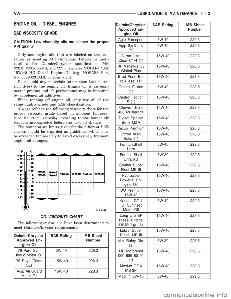
Always refer to the following viscosity chart for the
proper viscosity grade based on ambient tempera-
ture. Select oil viscosity according to the lowest air
temperature expected before the next oil change.
The temperature limits given for the different SAE
classes should be regarded as guidelines which may
be exceeded temporarily to avoid excessively frequent
engine oil changes.
The following engine oils have been determined to
meet DaimlerChrysler requirements:
DaimlerChrysler
Approved En-
gine OilSAE Rating MB Sheet
Number
76 Pure Syn-
thetic Motor Oil5W-40 229.3
76 Royal Triton
QLT15W-40 228.3
Agip All Guard
Motor Oil15W-40 228.3
DaimlerChrysler
Approved En-
gine OilSAE Rating MB Sheet
Number
Agip Eurosport 5W-40 229.3
Agip Synthetic
PC5W-40 229.3
Akron Ultra
Clear C1-4 (1)15W-40 228.3
BP Vanellus C6
Global Plus10W-40 228.3
Brad Penn Eu-
ro-Diesel LD15W-40 228.3
Castrol Elixion
(1)5W-40 228.5
Castrol Tection
S (1)15W-40 228.3
Chevron Delo
400 Multigrade15W-40 228.3
Diesel Special
Benz M&A15W-40 228.3
Dislub Premium 15W-40 228.3
Exxon XD-3
Extra (1)15W-40 228.3
FormulaShell
Ultra5W-40 229.3
FormulaShell
Ultra AB5W-30 229.5
Gonher Super
Fleet MB-III15W-40 228.3
Hydroclear
Power-D En-
gine Oil15W-40 228.3
IDO Premium
15W-4015W-40 228.3
Kendall GT-1
Full Synthetic
Motor Oil5W-40 229.3
Long Life EF
Diesel Engine
Oil Multigrade15W-40 228.3
Lubral Super
Diesel MB-III15W-40 228.3
Max Raloy Die-
sel5W-30 228.5
MB Motorenæl
000 989 60 01
1310W-40 228.5
Mexlub CF-4
MB-3P15W-40 228.3
Mobil 1 0W-40 0W-40 229.5
OIL VISCOSITY CHART
VALUBRICATION & MAINTENANCE 0 - 3