2006 MERCEDES-BENZ SPRINTER mirror
[x] Cancel search: mirrorPage 1955 of 2305
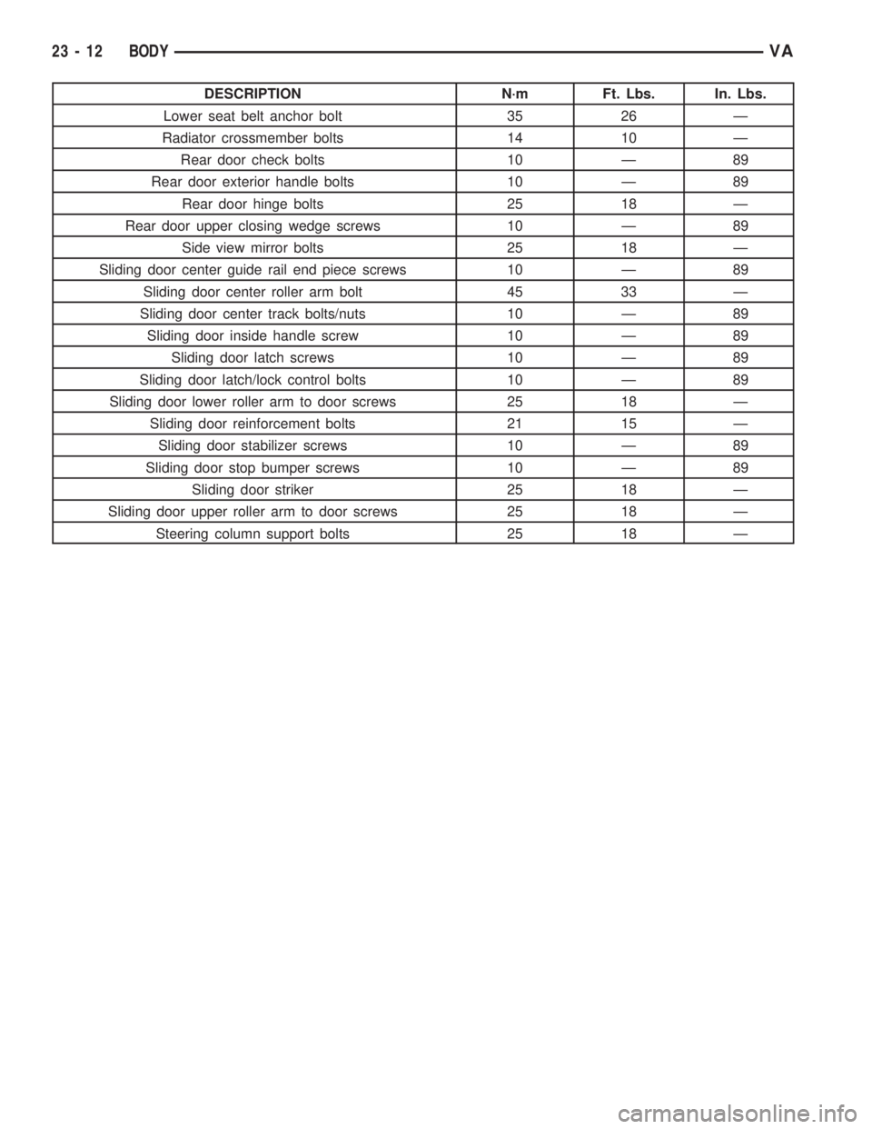
DESCRIPTION N´m Ft. Lbs. In. Lbs.
Lower seat belt anchor bolt 35 26 Ð
Radiator crossmember bolts 14 10 Ð
Rear door check bolts 10 Ð 89
Rear door exterior handle bolts 10 Ð 89
Rear door hinge bolts 25 18 Ð
Rear door upper closing wedge screws 10 Ð 89
Side view mirror bolts 25 18 Ð
Sliding door center guide rail end piece screws 10 Ð 89
Sliding door center roller arm bolt 45 33 Ð
Sliding door center track bolts/nuts 10 Ð 89
Sliding door inside handle screw 10 Ð 89
Sliding door latch screws 10 Ð 89
Sliding door latch/lock control bolts 10 Ð 89
Sliding door lower roller arm to door screws 25 18 Ð
Sliding door reinforcement bolts 21 15 Ð
Sliding door stabilizer screws 10 Ð 89
Sliding door stop bumper screws 10 Ð 89
Sliding door striker 25 18 Ð
Sliding door upper roller arm to door screws 25 18 Ð
Steering column support bolts 25 18 Ð
23 - 12 BODYVA
Page 1957 of 2305
(3) Install bracket onto check and install bracket
bolt/nut.
(4) Tighten bracket bolt/nut to 6 N´m (53 in. lbs.).
(5) Install check bracket onto a-pillar.
(6) Apply Loctitet243 sealant check strap bolts
and install bolts.
(7) Tighten the M8 bolts to 35 N´m (26 ft. lbs.) or
tighten the M6 bolts to 10 N´m (89 in. lbs.).
(8) Install trim panel. (Refer to 23 - BODY/DOOR -
FRONT/TRIM PANEL - INSTALLATION)
(9) Connect battery negative cable.
DOOR
REMOVAL
(1) Disconnect and isolate battery negative cable.
(2) Remove mirror. (Refer to 23 - BODY/EXTERI-
OR/SIDE VIEW MIRROR - REMOVAL)
(3) Position aside the wiring boot and disconnect
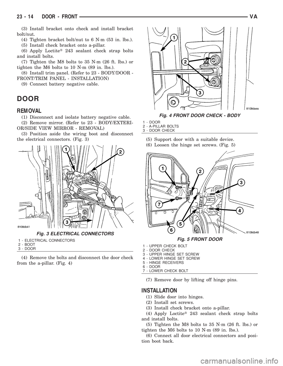
the electrical connectors. (Fig. 3)
(4) Remove the bolts and disconnect the door check
from the a-pillar. (Fig. 4)(5) Support door with a suitable device.
(6) Loosen the hinge set screws. (Fig. 5)
(7) Remove door by lifting off hinge pins.
INSTALLATION
(1) Slide door into hinges.
(2) Install set screws.
(3) Install check bracket onto a-pillar.
(4) Apply Loctitet243 sealant check strap bolts
and install bolts.
(5) Tighten the M8 bolts to 35 N´m (26 ft. lbs.) or
tighten the M6 bolts to 10 N´m (89 in. lbs.).
(6) Connect all door electrical connectors and posi-
tion boot back.
Fig. 3 ELECTRICAL CONNECTORS
1 - ELECTRICAL CONNECTORS
2 - BOOT
3 - DOOR
Fig. 4 FRONT DOOR CHECK - BODY
1 - DOOR
2 - A-PILLAR BOLTS
3 - DOOR CHECK
Fig. 5 FRONT DOOR
1 - UPPER CHECK BOLT
2 - DOOR CHECK
3 - UPPER HINGE SET SCREW
4 - LOWER HINGE SET SCREW
5 - HINGE RECEIVERS
6 - DOOR
7 - LOWER CHECK BOLT
23 - 14 DOOR - FRONTVA
Page 1958 of 2305
(7) Install mirror. (Refer to 23 - BODY/EXTERI-
OR/SIDE VIEW MIRROR - INSTALLATION)
(8) Adjust door if required. (Refer to 23 - BODY/
DOOR - FRONT/DOOR - ADJUSTMENTS)
(9) Connect battery negative cable.
ADJUSTMENTS
ADJUSTMENT
NOTE: Door adjustment measurements should be
taken from stationary or welded body panels like
the roof, rocker or quarter panels.
²During adjustment procedures, it is recom-
mended that all the hinge fasteners be loosened
except for the upper most fasteners. Adjustments
can be made using the upper bolts to hold the door
with final torque of the fasteners occurring after
correct door positioning is achieved.
²A suitable body sealant should be used when
removing or moving the hinges.
(1) Check door alignment. (Refer to 23 - BODY/
BODY STRUCTURE/GAP AND FLUSH - SPECIFI-
CATIONS)
(2) If adjustment is required, remove latch striker.
(Refer to 23 - BODY/DOOR - FRONT/LATCH
STRIKER - REMOVAL)
(3) Remove side view mirror. (Refer to 23 - BODY/
EXTERIOR/SIDE VIEW MIRROR - REMOVAL)
(4) Loosen hinge bolts and adjust door gap and
align ridge pattern as necessary.
(5) Tighten hinge bolts to 25 N´m (18 ft. lbs.).
(6) Install latch striker and adjust flush measure-
ment as necessary. (Refer to 23 - BODY/DOOR -
FRONT/LATCH STRIKER - INSTALLATION)
(7) Install side view mirror. (Refer to 23 - BODY/
EXTERIOR/SIDE VIEW MIRROR - INSTALLA-
TION)
DOOR GLASS
REMOVAL
(1) Remove the regulator. (Refer to 23 - BODY/
DOOR - FRONT/WINDOW REGULATOR - POWER
or MANUAL - REMOVAL)
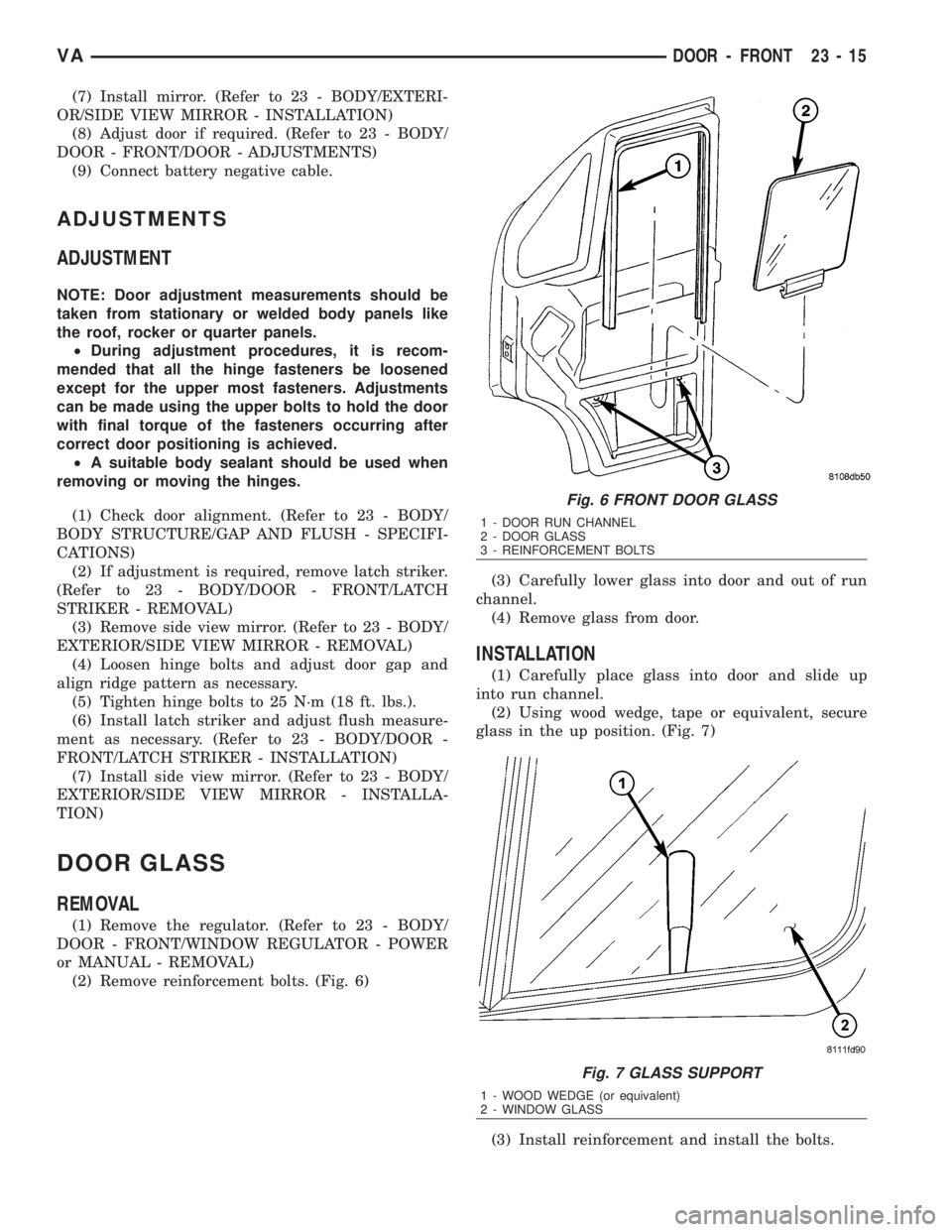
(2) Remove reinforcement bolts. (Fig. 6)(3) Carefully lower glass into door and out of run
channel.
(4) Remove glass from door.
INSTALLATION
(1) Carefully place glass into door and slide up
into run channel.
(2) Using wood wedge, tape or equivalent, secure
glass in the up position. (Fig. 7)
(3) Install reinforcement and install the bolts.
Fig. 6 FRONT DOOR GLASS
1 - DOOR RUN CHANNEL
2 - DOOR GLASS
3 - REINFORCEMENT BOLTS
Fig. 7 GLASS SUPPORT
1 - WOOD WEDGE (or equivalent)
2 - WINDOW GLASS
VADOOR - FRONT 23 - 15
Page 1960 of 2305
(4) Tighten bolt to 10 N´m (89 in. lbs.).
HINGE
REMOVAL
NOTE: It is not necessary to remove the door to
replace the hinges if they are replaced one at a
time.
(1) Using a grease pencil or equivalent, mark the
position of the hinge on the door.
(2) Remove side view mirror. (Refer to 23 - BODY/
EXTERIOR/SIDE VIEW MIRROR - REMOVAL)
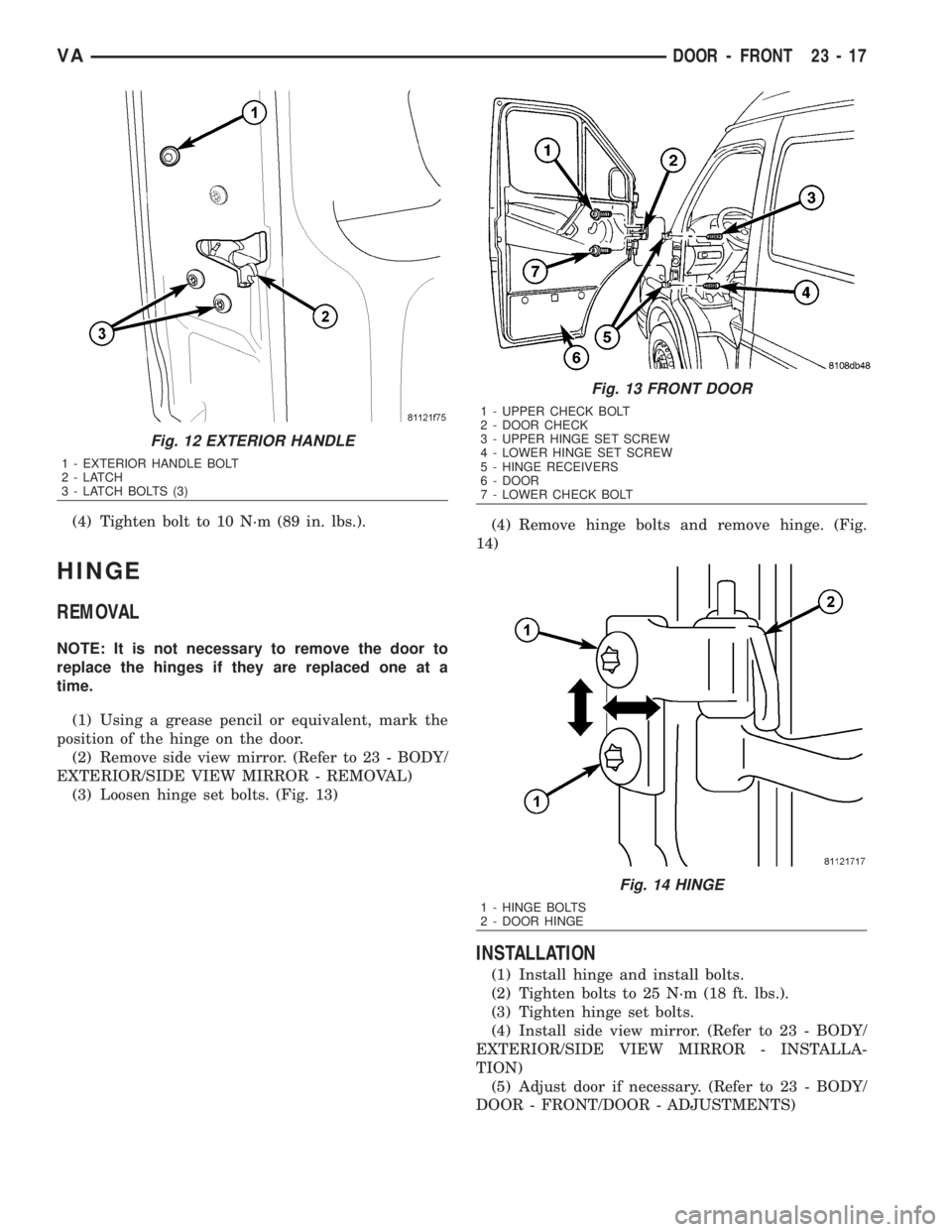
(3) Loosen hinge set bolts. (Fig. 13)(4) Remove hinge bolts and remove hinge. (Fig.
14)
INSTALLATION
(1) Install hinge and install bolts.
(2) Tighten bolts to 25 N´m (18 ft. lbs.).
(3) Tighten hinge set bolts.
(4) Install side view mirror. (Refer to 23 - BODY/
EXTERIOR/SIDE VIEW MIRROR - INSTALLA-
TION)
(5) Adjust door if necessary. (Refer to 23 - BODY/
DOOR - FRONT/DOOR - ADJUSTMENTS)
Fig. 12 EXTERIOR HANDLE
1 - EXTERIOR HANDLE BOLT
2-LATCH
3 - LATCH BOLTS (3)
Fig. 13 FRONT DOOR
1 - UPPER CHECK BOLT
2 - DOOR CHECK
3 - UPPER HINGE SET SCREW
4 - LOWER HINGE SET SCREW
5 - HINGE RECEIVERS
6 - DOOR
7 - LOWER CHECK BOLT
Fig. 14 HINGE
1 - HINGE BOLTS
2 - DOOR HINGE
VADOOR - FRONT 23 - 17
Page 1991 of 2305
EXTERIOR
TABLE OF CONTENTS
page page
FUEL FILL DOOR
REMOVAL.............................48
INSTALLATION.........................48
GRILLE
REMOVAL.............................48
INSTALLATION.........................48
LICENSE PLATE BRACKET
REMOVAL.............................48
INSTALLATION.........................48RADIATOR CROSSMEMBER
REMOVAL.............................49
INSTALLATION.........................49
SIDE VIEW MIRROR
REMOVAL.............................49
INSTALLATION.........................50
SIDE VIEW MIRROR - GLASS
REMOVAL.............................50
INSTALLATION.........................50
FUEL FILL DOOR
REMOVAL
(1) Open passenger compartment door.
(2) Open fuel fill door.
(3) Using a trim stick C-4755 or equivalent, dis-
connect the filler cap tether.
(4) Remove two bolts and remove filler door.
INSTALLATION
(1) Install the door and bolts.
(2) Connect filler cap tether.
(3) Close doors.
GRILLE
REMOVAL
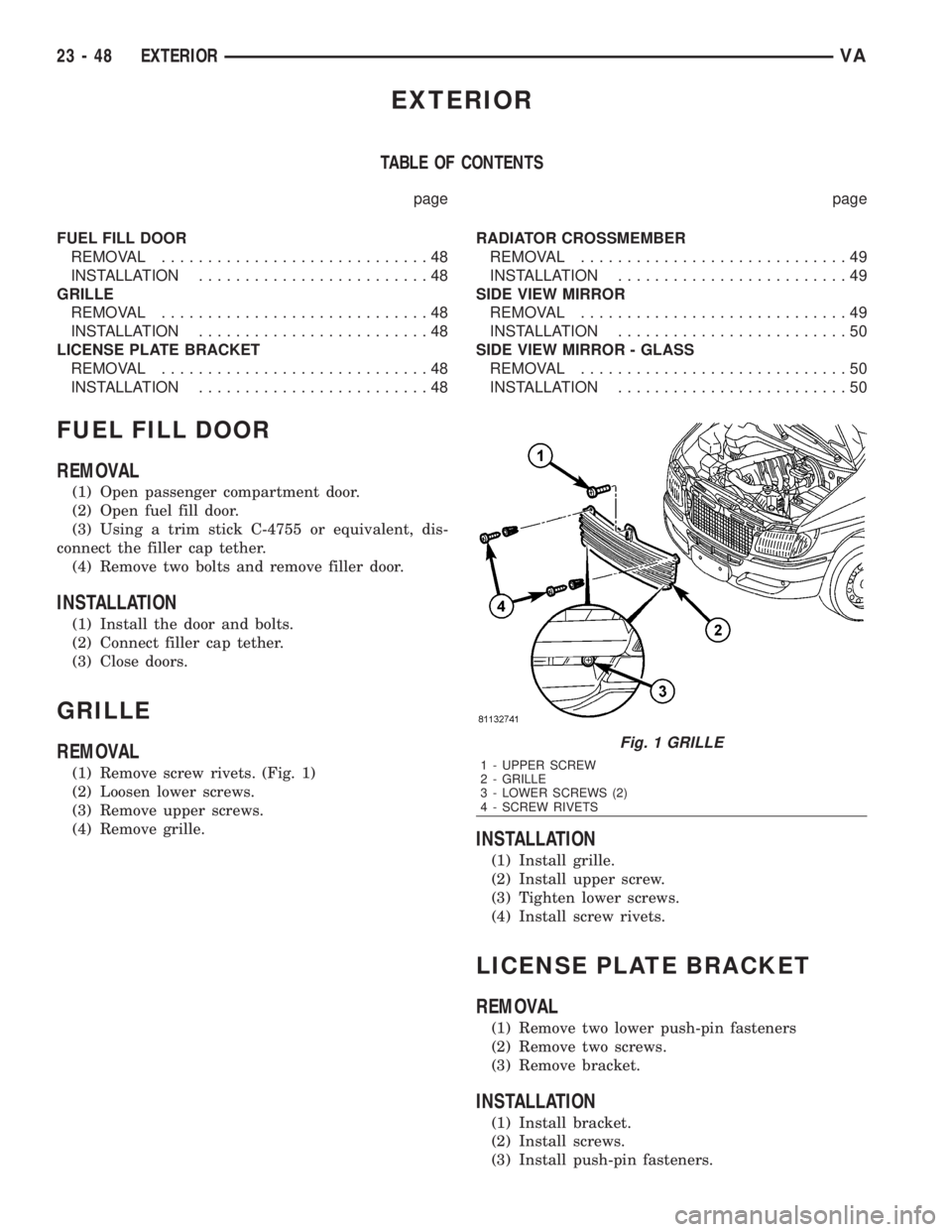
(1) Remove screw rivets. (Fig. 1)
(2) Loosen lower screws.
(3) Remove upper screws.
(4) Remove grille.
INSTALLATION
(1) Install grille.
(2) Install upper screw.
(3) Tighten lower screws.
(4) Install screw rivets.
LICENSE PLATE BRACKET
REMOVAL
(1) Remove two lower push-pin fasteners
(2) Remove two screws.
(3) Remove bracket.
INSTALLATION
(1) Install bracket.
(2) Install screws.
(3) Install push-pin fasteners.
Fig. 1 GRILLE
1 - UPPER SCREW
2 - GRILLE
3 - LOWER SCREWS (2)
4 - SCREW RIVETS
23 - 48 EXTERIORVA
Page 1992 of 2305
RADIATOR CROSSMEMBER
REMOVAL
(1) Remove grille. (Refer to 23 - BODY/EXTERI-
OR/GRILLE - REMOVAL)
(2) Remove headlamps. (Refer to 8 - ELECTRI-
CAL/LAMPS/LIGHTING - EXTERIOR/FRONT
LAMP UNIT - REMOVAL)
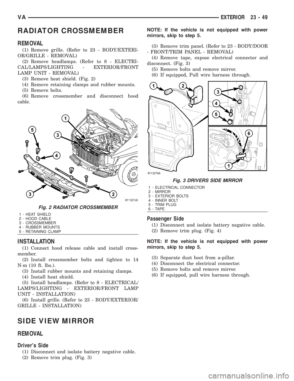
(3) Remove heat shield. (Fig. 2)
(4) Remove retaining clamps and rubber mounts.
(5) Remove bolts.
(6) Remove crossmember and disconnect hood
cable.
INSTALLATION
(1) Connect hood release cable and install cross-
member.
(2) Install crossmember bolts and tighten to 14
N´m (10 ft. lbs.).
(3) Install rubber mounts and retaining clamps.
(4) Install heat shield.
(5) Install headlamps. (Refer to 8 - ELECTRICAL/
LAMPS/LIGHTING - EXTERIOR/FRONT LAMP
UNIT - INSTALLATION)
(6) Install grille. (Refer to 23 - BODY/EXTERIOR/
GRILLE - INSTALLATION)
SIDE VIEW MIRROR
REMOVAL
Driver's Side
(1) Disconnect and isolate battery negative cable.
(2) Remove trim plug. (Fig. 3)NOTE: If the vehicle is not equipped with power
mirrors, skip to step 5.
(3) Remove trim panel. (Refer to 23 - BODY/DOOR
- FRONT/TRIM PANEL - REMOVAL)
(4) Remove tape, expose electrical connector and
disconnect. (Fig. 3)
(5) Remove bolts and remove mirror.
(6) If equipped, Pull wire harness through.
Passenger Side
(1) Disconnect and isolate battery negative cable.
(2) Remove trim plug. (Fig. 4)
NOTE: If the vehicle is not equipped with power
mirrors, skip to step 5.
(3) Separate dust boot from a-pillar.
(4) Disconnect the electrical connector.
(5) Remove bolts and remove mirror.
(6) If equipped, pull wire harness through.
Fig. 2 RADIATOR CROSSMEMBER
1 - HEAT SHIELD
2 - HOOD CABLE
3 - CROSSMEMBER
4 - RUBBER MOUNTS
5 - RETAINING CLAMP
Fig. 3 DRIVERS SIDE MIRROR
1 - ELECTRICAL CONNECTOR
2 - MIRROR
3 - EXTERIOR BOLTS
4 - INNER BOLT
5 - TRIM PLUG
6 - TAPE
VAEXTERIOR 23 - 49
Page 1993 of 2305
INSTALLATION
Driver's Side
(1) If equipped, pull wire harness through door.
(2) Install mirror and bolts.
(3) Tighten the bolts to 25 N´m (18 ft. lbs.).
NOTE: If vehicle is not equipped with power mir-
rors, skip to step 6.
(4) Connect electrical connector and replace tape.
(5) Install trim panel. (Refer to 23 - BODY/DOOR -
FRONT/TRIM PANEL - INSTALLATION)
(6) Install trim plug.
(7) Connect battery negative cable.
Passenger Side
(1) If equipped, pull wire harness through door.
(2) Install mirror and bolts.
(3) Tighten the bolts to 25 N´m (18 ft. lbs.).
NOTE: If vehicle is not equipped with power mir-
rors, skip to step 6.
(4) Connect the electrical connector.
(5) Connect dust boot to a-pillar.
(6) Install trim plug.
(7) Connect battery negative cable.
SIDE VIEW MIRROR - GLASS
REMOVAL
(1) Disconnect and isolate battery negative cable.
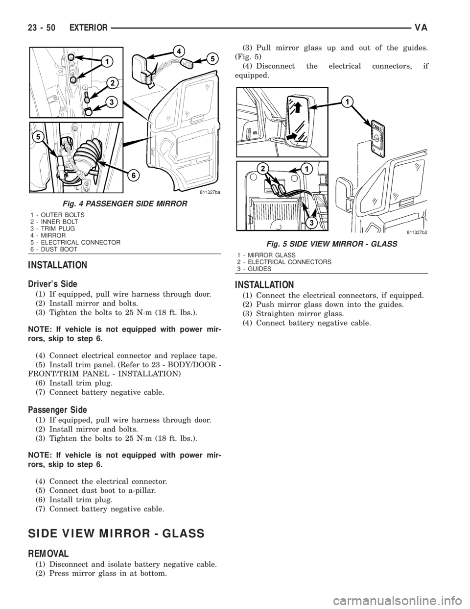
(2) Press mirror glass in at bottom.(3) Pull mirror glass up and out of the guides.
(Fig. 5)
(4) Disconnect the electrical connectors, if
equipped.
INSTALLATION
(1) Connect the electrical connectors, if equipped.
(2) Push mirror glass down into the guides.
(3) Straighten mirror glass.
(4) Connect battery negative cable.
Fig. 4 PASSENGER SIDE MIRROR
1 - OUTER BOLTS
2 - INNER BOLT
3 - TRIM PLUG
4 - MIRROR
5 - ELECTRICAL CONNECTOR
6 - DUST BOOT
Fig. 5 SIDE VIEW MIRROR - GLASS
1 - MIRROR GLASS
2 - ELECTRICAL CONNECTORS
3 - GUIDES
23 - 50 EXTERIORVA
Page 2013 of 2305
INTERIOR
TABLE OF CONTENTS
page page
INTERIOR
CAUTION.............................70
A-PILLAR TRIM
REMOVAL.............................70
INSTALLATION.........................71
ASSIST HANDLE
REMOVAL.............................71
INSTALLATION.........................71
B-PILLAR TRIM
REMOVAL.............................71
INSTALLATION.........................72
BULKHEAD TRIM PANEL
REMOVAL.............................72
INSTALLATION.........................72
CARPETS AND FLOOR MATS
REMOVAL.............................72
INSTALLATION.........................73
COWL TRIM
REMOVAL.............................73
INSTALLATION.........................73
D-PILLAR TRIM
REMOVAL.............................73INSTALLATION.........................73
HEADLINER
REMOVAL.............................73
INSTALLATION.........................74
QUARTER TRIM PANEL
REMOVAL.............................74
INSTALLATION.........................75
REAR VIEW MIRROR
REMOVAL.............................75
INSTALLATION
INSTALLATION.......................75
INSTALLATION - REAR VIEW MIRROR
SUPPORT BRACKET...................75
STEPWELL SCUFF PADS
REMOVAL.............................75
INSTALLATION.........................76
SUN VISOR
REMOVAL.............................76
INSTALLATION.........................76
INTERIOR
CAUTION
CAUTION:: Do not attempt to remove interior trim
panels/moldings without first removing the neces-
sary adjacent panels. To avoid damaging the pan-
els, ensure that all the screws and clips are
removed before attempting to remove an interior
trim panel/molding. Trim panels are somewhat flex-
ible but can be damaged if handled improperly.
A - PILLAR TRIM
REMOVAL
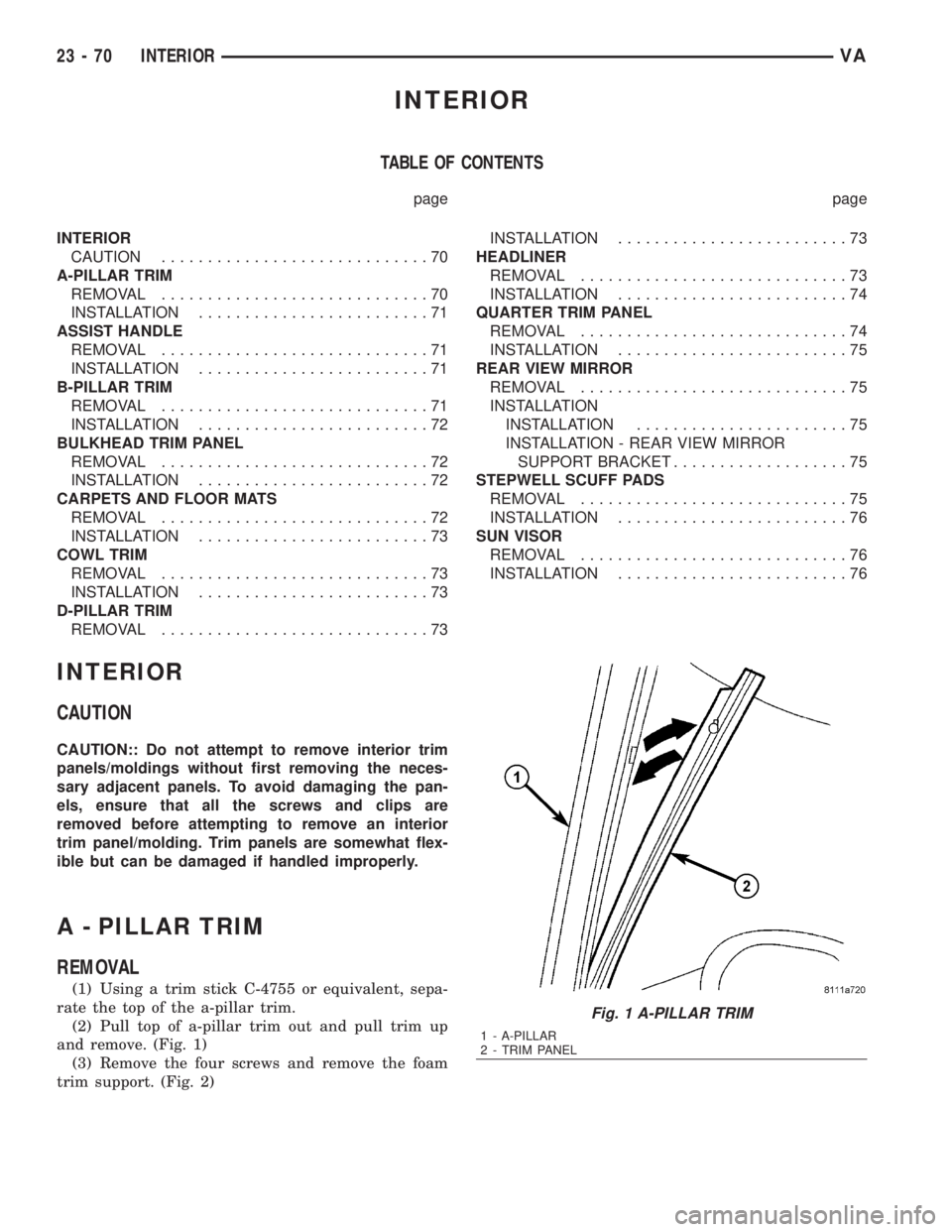
(1) Using a trim stick C-4755 or equivalent, sepa-
rate the top of the a-pillar trim.
(2) Pull top of a-pillar trim out and pull trim up
and remove. (Fig. 1)
(3) Remove the four screws and remove the foam
trim support. (Fig. 2)
Fig. 1 A-PILLAR TRIM
1 - A-PILLAR
2 - TRIM PANEL
23 - 70 INTERIORVA