2006 MERCEDES-BENZ SPRINTER mirror
[x] Cancel search: mirrorPage 1438 of 2305
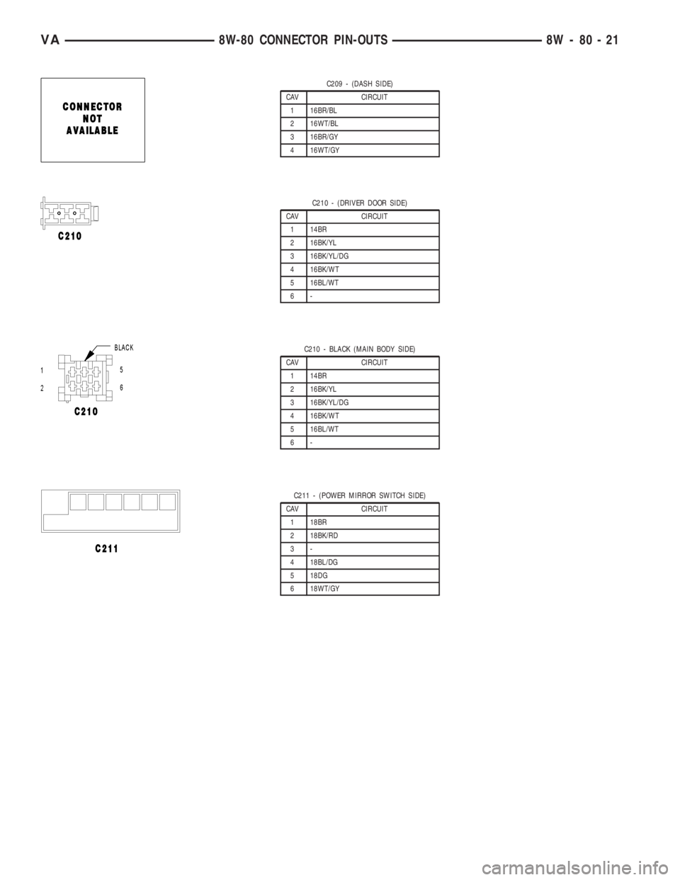
C209 - (DASH SIDE)
CAV CIRCUIT
1 16BR/BL
2 16WT/BL
3 16BR/GY
4 16WT/GY
C210 - (DRIVER DOOR SIDE)
CAV CIRCUIT
1 14BR
2 16BK/YL
3 16BK/YL/DG
4 16BK/WT
5 16BL/WT
6-
C210 - BLACK (MAIN BODY SIDE)
CAV CIRCUIT
1 14BR
2 16BK/YL
3 16BK/YL/DG
4 16BK/WT
5 16BL/WT
6-
C211 - (POWER MIRROR SWITCH SIDE)
CAV CIRCUIT
1 18BR
2 18BK/RD
3-
4 18BL/DG
5 18DG
6 18WT/GY
VA8W-80 CONNECTOR PIN-OUTS 8W - 80 - 21
Page 1439 of 2305
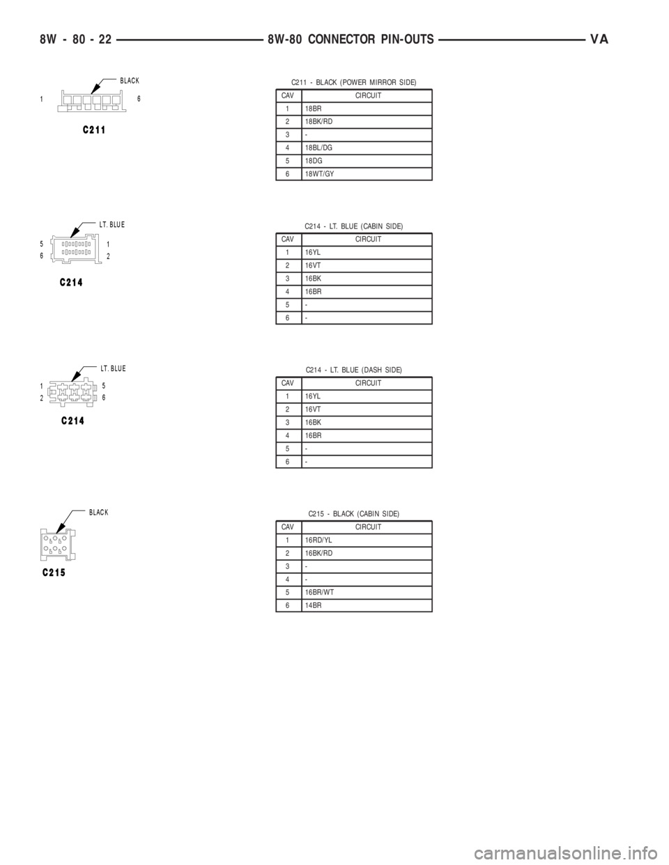
C211 - BLACK (POWER MIRROR SIDE)
CAV CIRCUIT
1 18BR
2 18BK/RD
3-
4 18BL/DG
5 18DG
6 18WT/GY
C214 - LT. BLUE (CABIN SIDE)
CAV CIRCUIT
1 16YL
2 16VT
3 16BK
4 16BR
5-
6-
C214 - LT. BLUE (DASH SIDE)
CAV CIRCUIT
1 16YL
2 16VT
3 16BK
4 16BR
5-
6-
C215 - BLACK (CABIN SIDE)
CAV CIRCUIT
1 16RD/YL
2 16BK/RD
3-
4-
5 16BR/WT
6 14BR
8W - 80 - 22 8W-80 CONNECTOR PIN-OUTSVA
Page 1484 of 2305
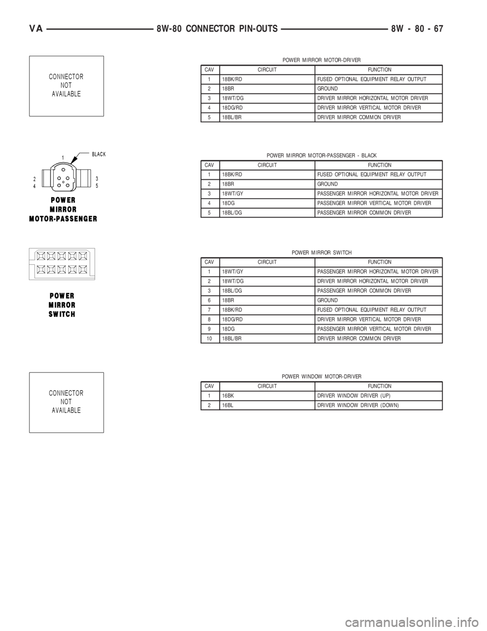
POWER MIRROR MOTOR-DRIVER
CAV CIRCUIT FUNCTION
1 18BK/RD FUSED OPTIONAL EQUIPMENT RELAY OUTPUT
2 18BR GROUND
3 18WT/DG DRIVER MIRROR HORIZONTAL MOTOR DRIVER
4 18DG/RD DRIVER MIRROR VERTICAL MOTOR DRIVER
5 18BL/BR DRIVER MIRROR COMMON DRIVER
POWER MIRROR MOTOR-PASSENGER - BLACK
CAV CIRCUIT FUNCTION
1 18BK/RD FUSED OPTIONAL EQUIPMENT RELAY OUTPUT
2 18BR GROUND
3 18WT/GY PASSENGER MIRROR HORIZONTAL MOTOR DRIVER
4 18DG PASSENGER MIRROR VERTICAL MOTOR DRIVER
5 18BL/DG PASSENGER MIRROR COMMON DRIVER
POWER MIRROR SWITCH
CAV CIRCUIT FUNCTION
1 18WT/GY PASSENGER MIRROR HORIZONTAL MOTOR DRIVER
2 18WT/DG DRIVER MIRROR HORIZONTAL MOTOR DRIVER
3 18BL/DG PASSENGER MIRROR COMMON DRIVER
6 18BR GROUND
7 18BK/RD FUSED OPTIONAL EQUIPMENT RELAY OUTPUT
8 18DG/RD DRIVER MIRROR VERTICAL MOTOR DRIVER
9 18DG PASSENGER MIRROR VERTICAL MOTOR DRIVER
10 18BL/BR DRIVER MIRROR COMMON DRIVER
POWER WINDOW MOTOR-DRIVER
CAV CIRCUIT FUNCTION
1 16BK DRIVER WINDOW DRIVER (UP)
2 16BL DRIVER WINDOW DRIVER (DOWN)
VA8W-80 CONNECTOR PIN-OUTS 8W - 80 - 67
Page 1510 of 2305
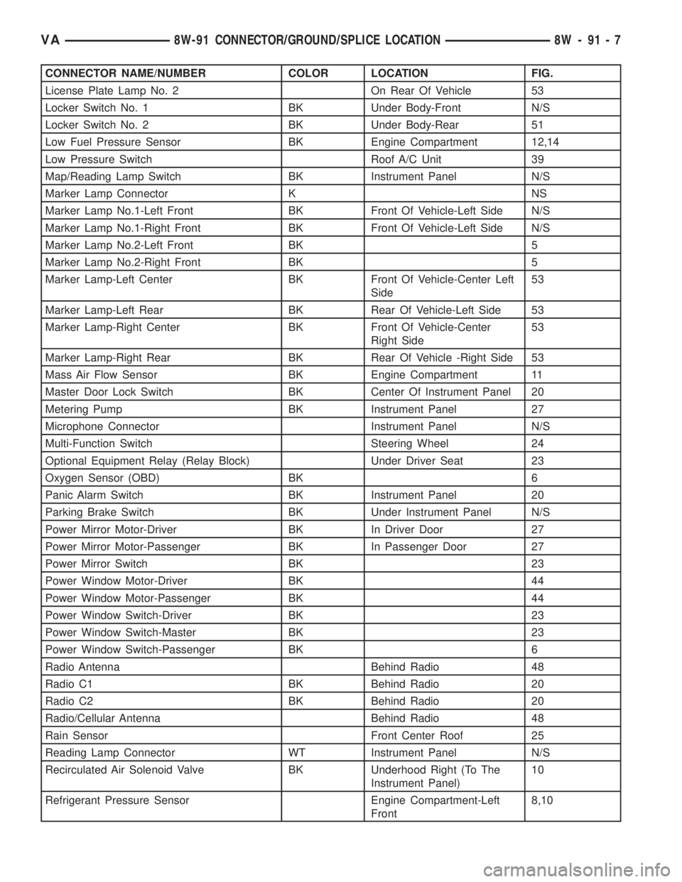
CONNECTOR NAME/NUMBER COLOR LOCATION FIG.
License Plate Lamp No. 2 On Rear Of Vehicle 53
Locker Switch No. 1 BK Under Body-Front N/S
Locker Switch No. 2 BK Under Body-Rear 51
Low Fuel Pressure Sensor BK Engine Compartment 12,14
Low Pressure Switch Roof A/C Unit 39
Map/Reading Lamp Switch BK Instrument Panel N/S
Marker Lamp Connector K NS
Marker Lamp No.1-Left Front BK Front Of Vehicle-Left Side N/S
Marker Lamp No.1-Right Front BK Front Of Vehicle-Left Side N/S
Marker Lamp No.2-Left Front BK 5
Marker Lamp No.2-Right Front BK 5
Marker Lamp-Left Center BK Front Of Vehicle-Center Left
Side53
Marker Lamp-Left Rear BK Rear Of Vehicle-Left Side 53
Marker Lamp-Right Center BK Front Of Vehicle-Center
Right Side53
Marker Lamp-Right Rear BK Rear Of Vehicle -Right Side 53
Mass Air Flow Sensor BK Engine Compartment 11
Master Door Lock Switch BK Center Of Instrument Panel 20
Metering Pump BK Instrument Panel 27
Microphone Connector Instrument Panel N/S
Multi-Function Switch Steering Wheel 24
Optional Equipment Relay (Relay Block) Under Driver Seat 23
Oxygen Sensor (OBD) BK 6
Panic Alarm Switch BK Instrument Panel 20
Parking Brake Switch BK Under Instrument Panel N/S
Power Mirror Motor-Driver BK In Driver Door 27
Power Mirror Motor-Passenger BK In Passenger Door 27
Power Mirror Switch BK 23
Power Window Motor-Driver BK 44
Power Window Motor-Passenger BK 44
Power Window Switch-Driver BK 23
Power Window Switch-Master BK 23
Power Window Switch-Passenger BK 6
Radio Antenna Behind Radio 48
Radio C1 BK Behind Radio 20
Radio C2 BK Behind Radio 20
Radio/Cellular Antenna Behind Radio 48
Rain Sensor Front Center Roof 25
Reading Lamp Connector WT Instrument Panel N/S
Recirculated Air Solenoid Valve BK Underhood Right (To The
Instrument Panel)10
Refrigerant Pressure Sensor Engine Compartment-Left
Front8,10
VA8W-91 CONNECTOR/GROUND/SPLICE LOCATION 8W - 91 - 7
Page 1543 of 2305
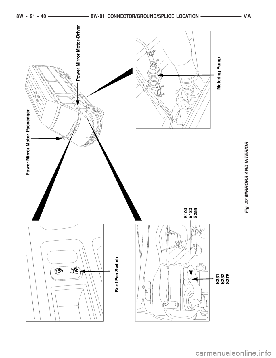
Fig. 27 MIRRORS AND INTERIOR
8W - 91 - 40 8W-91 CONNECTOR/GROUND/SPLICE LOCATIONVA
Page 1786 of 2305
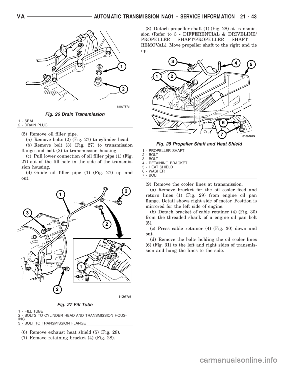
(5) Remove oil filler pipe.
(a) Remove bolts (2) (Fig. 27) to cylinder head.
(b) Remove bolt (3) (Fig. 27) to transmission
flange and bolt (2) to transmission housing.
(c) Pull lower connection of oil filler pipe (1) (Fig.
27) out of the fill hole in the side of the transmis-
sion housing.
(d) Guide oil filler pipe (1) (Fig. 27) up and
out.
(6) Remove exhaust heat shield (5) (Fig. 28).
(7) Remove retaining bracket (4) (Fig. 28).(8) Detach propeller shaft (1) (Fig. 28) at transmis-
sion (Refer to 3 - DIFFERENTIAL & DRIVELINE/
PROPELLER SHAFT/PROPELLER SHAFT -
REMOVAL). Move propeller shaft to the right and tie
up.
(9) Remove the cooler lines at transmission.
(a) Remove bracket for the oil cooler feed and
return lines (1) (Fig. 29) from engine oil pan
flange. Detail shows right side of motor. Position is
mirrored for the left side of engine.
(b) Detach bracket of cable retainer (4) (Fig. 30)
from the threaded shank of a engine oil pan bolt
(5).
(c) Press cable retainer (4) (Fig. 30) down and
out.
(d) Remove the bolts holding the oil cooler lines
(6) (Fig. 31) to the left and right sides of transmis-
sion and hang the lines to the side.
Fig. 26 Drain Transmission
1 - SEAL
2 - DRAIN PLUG
Fig. 27 Fill Tube
1 - FILL TUBE
2 - BOLTS TO CYLINDER HEAD AND TRANSMISSION HOUS-
ING
3 - BOLT TO TRANSMISSION FLANGE
Fig. 28 Propeller Shaft and Heat Shield
1 - PROPELLER SHAFT
2 - BOLT
3 - BOLT
4 - RETAINING BRACKET
5 - HEAT SHIELD
6 - WASHER
7 - BOLT
VAAUTOMATIC TRANSMISSION NAG1 - SERVICE INFORMATION 21 - 43
Page 1805 of 2305
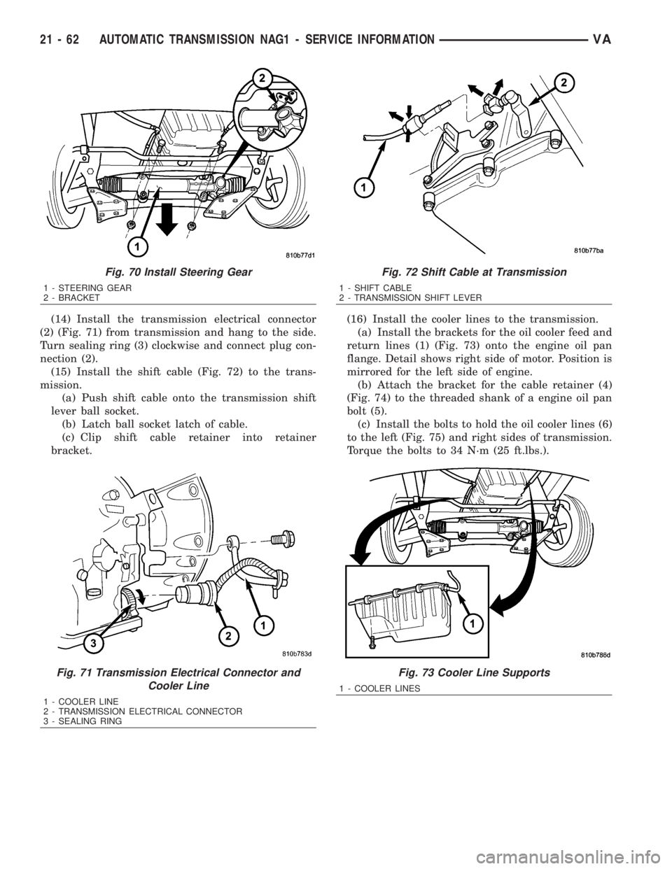
(14) Install the transmission electrical connector
(2) (Fig. 71) from transmission and hang to the side.
Turn sealing ring (3) clockwise and connect plug con-
nection (2).
(15) Install the shift cable (Fig. 72) to the trans-
mission.
(a) Push shift cable onto the transmission shift
lever ball socket.
(b) Latch ball socket latch of cable.
(c) Clip shift cable retainer into retainer
bracket.(16) Install the cooler lines to the transmission.
(a) Install the brackets for the oil cooler feed and
return lines (1) (Fig. 73) onto the engine oil pan
flange. Detail shows right side of motor. Position is
mirrored for the left side of engine.
(b) Attach the bracket for the cable retainer (4)
(Fig. 74) to the threaded shank of a engine oil pan
bolt (5).
(c) Install the bolts to hold the oil cooler lines (6)
to the left (Fig. 75) and right sides of transmission.
Torque the bolts to 34 N´m (25 ft.lbs.).
Fig. 70 Install Steering Gear
1 - STEERING GEAR
2 - BRACKET
Fig. 71 Transmission Electrical Connector and
Cooler Line
1 - COOLER LINE
2 - TRANSMISSION ELECTRICAL CONNECTOR
3 - SEALING RING
Fig. 72 Shift Cable at Transmission
1 - SHIFT CABLE
2 - TRANSMISSION SHIFT LEVER
Fig. 73 Cooler Line Supports
1 - COOLER LINES
21 - 62 AUTOMATIC TRANSMISSION NAG1 - SERVICE INFORMATIONVA
Page 1945 of 2305
aligned and sealed. If component alignment or seal-
ing is necessary, refer to the appropriate section of
this group for proper procedures.
WATER LEAK TESTS
WARNING: DO NOT USE ELECTRIC SHOP LIGHTS
OR TOOLS IN WATER TEST AREA. PERSONAL
INJURY CAN RESULT.
When the conditions causing a water leak have
been determined, simulate the conditions as closely
as possible.
²If a leak occurs with the vehicle parked in a
steady light rain, flood the leak area with an open-
ended garden hose.
²If a leak occurs while driving at highway speeds
in a steady rain, test the leak area with a reasonable
velocity stream or fan spray of water. Direct the
spray in a direction comparable to actual conditions.
²If a leak occurs when the vehicle is parked on an
incline, hoist the end or side of the vehicle to simu-
late this condition. This method can be used when
the leak occurs when the vehicle accelerates, stops or
turns. If the leak occurs on acceleration, hoist the
front of the vehicle. If the leak occurs when braking,
hoist the back of the vehicle. If the leak occurs on left
turns, hoist the left side of the vehicle. If the leak
occurs on right turns, hoist the right side of the vehi-
cle. For hoisting recommendations (Refer to LUBRI-
CATION & MAINTENANCE/HOISTING -
STANDARD PROCEDURE).
WATER LEAK DETECTION
To detect a water leak point-of-entry, do a water
test and watch for water tracks or droplets forming
on the inside of the vehicle. If necessary, remove inte-
rior trim covers or panels to gain visual access to the
leak area. If the hose cannot be positioned without
being held, have someone help do the water test.
Some water leaks must be tested for a considerable
length of time to become apparent. When a leak
appears, find the highest point of the water track or
drop. The highest point usually will show the point of
entry. After leak point has been found, repair the
leak and water test to verify that the leak has
stopped.
Locating the entry point of water that is leaking
into a cavity between panels can be difficult. The
trapped water may splash or run from the cavity,
often at a distance from the entry point. Most water
leaks of this type become apparent after accelerating,
stopping, turning, or when on an incline.
MIRROR INSPECTION METHOD
When a leak point area is visually obstructed, use
a suitable mirror to gain visual access. A mirror canalso be used to deflect light to a limited-access area
to assist in locating a leak point.
BRIGHT LIGHT LEAK TEST METHOD
Some water leaks in the luggage compartment can
be detected without water testing. Position the vehi-
cle in a brightly lit area. From inside the darkened
luggage compartment inspect around seals and body
seams. If necessary, have a helper direct a drop light
over the suspected leak areas around the luggage
compartment. If light is visible through a normally
sealed location, water could enter through the open-
ing.
PRESSURIZED LEAK TEST METHOD
When a water leak into the passenger compart-
ment cannot be detected by water testing, pressurize
the passenger compartment and soap test exterior of
the vehicle. To pressurize the passenger compart-
ment, close all doors and windows, start engine, and
set heater control to high blower in HEAT position. If
engine can not be started, connect a charger to the
battery to ensure adequate voltage to the blower.
With interior pressurized, apply dish detergent solu-
tion to suspected leak area on the exterior of the
vehicle. Apply detergent solution with spray device or
soft bristle brush. If soap bubbles occur at a body
seam, joint, seal or gasket, the leak entry point could
be at that location.
DIAGNOSIS AND TESTING - WIND NOISE
Wind noise is the result of most air leaks. Air leaks
can be caused by poor sealing, improper body compo-
nent alignment, body seam porosity, or missing plugs
in the engine compartment or door hinge pillar areas.
All body sealing points should be airtight in normal
driving conditions. Moving sealing surfaces will not
always seal airtight under all conditions. At times,
side glass or door seals will allow wind noise to be
noticed in the passenger compartment during high
cross winds. Over compensating on door or glass
adjustments to stop wind noise that occurs under
severe conditions can cause premature seal wear and
excessive closing or latching effort. After a repair pro-
cedure has been performed, test vehicle to verify
noise has stopped before returning vehicle to use.
VISUAL INSPECTION BEFORE TESTS
Verify that floor and body plugs are in place and
body components are aligned and sealed. If compo-
nent alignment or sealing is necessary, refer to the
appropriate section of this group for proper proce-
dures.
ROAD TESTING WIND NOISE
(1) Drive the vehicle to verify the general location
of the wind noise.
23 - 2 BODYVA