2006 MERCEDES-BENZ SPRINTER sensor
[x] Cancel search: sensorPage 1029 of 2305
INSTALLATION
The following procedure is for replacement of a
faulty or damaged side curtain airbag. If the airbag
is faulty or damaged, but not deployed, review the
recommended procedures for handling non-deployed
supplemental restraints. (Refer to 8 - ELECTRICAL/
RESTRAINTS - STANDARD PROCEDURE - HAN-
DLING NON-DEPLOYED SUPPLEMENTAL
RESTRAINTS). If the side curtain airbag has been
deployed, review the recommended procedures for
service after a supplemental restraint deployment
before removing the airbag from the vehicle. (Refer to
8 - ELECTRICAL/RESTRAINTS - STANDARD PRO-
CEDURE - SERVICE AFTER A SUPPLEMENTAL
RESTRAINT DEPLOYMENT).
WARNING: To avoid personal injury or death, on
vehicles equipped with airbags, disable the supple-
mental restraint system before attempting any
steering wheel, steering column, airbag, seat belt
tensioner, impact sensor, or instrument panel com-
ponent diagnosis or service. Disconnect and isolate
the battery negative (ground) cable, then wait two
minutes for the system capacitor to discharge
before performing further diagnosis or service. This
is the only sure way to disable the supplemental
restraint system. Failure to take the proper precau-
tions could result in accidental airbag deployment.
WARNING: To avoid personal injury or death, when
removing a deployed airbag, rubber gloves, eye
protection, and a long-sleeved shirt should be
worn. There may be deposits on the airbag unit and
other interior surfaces. In large doses, these depos-
its may cause irritation to the skin and eyes.WARNING: To avoid personal injury or death, use
extreme care to prevent any foreign material from
entering the side curtain airbag, or becoming
entrapped between the side curtain airbag cushion
and the roof rail garnish molding. Failure to
observe this warning could result in occupant inju-
ries upon airbag deployment.
(1) Position the side curtain airbag into the vehicle
as a unit.
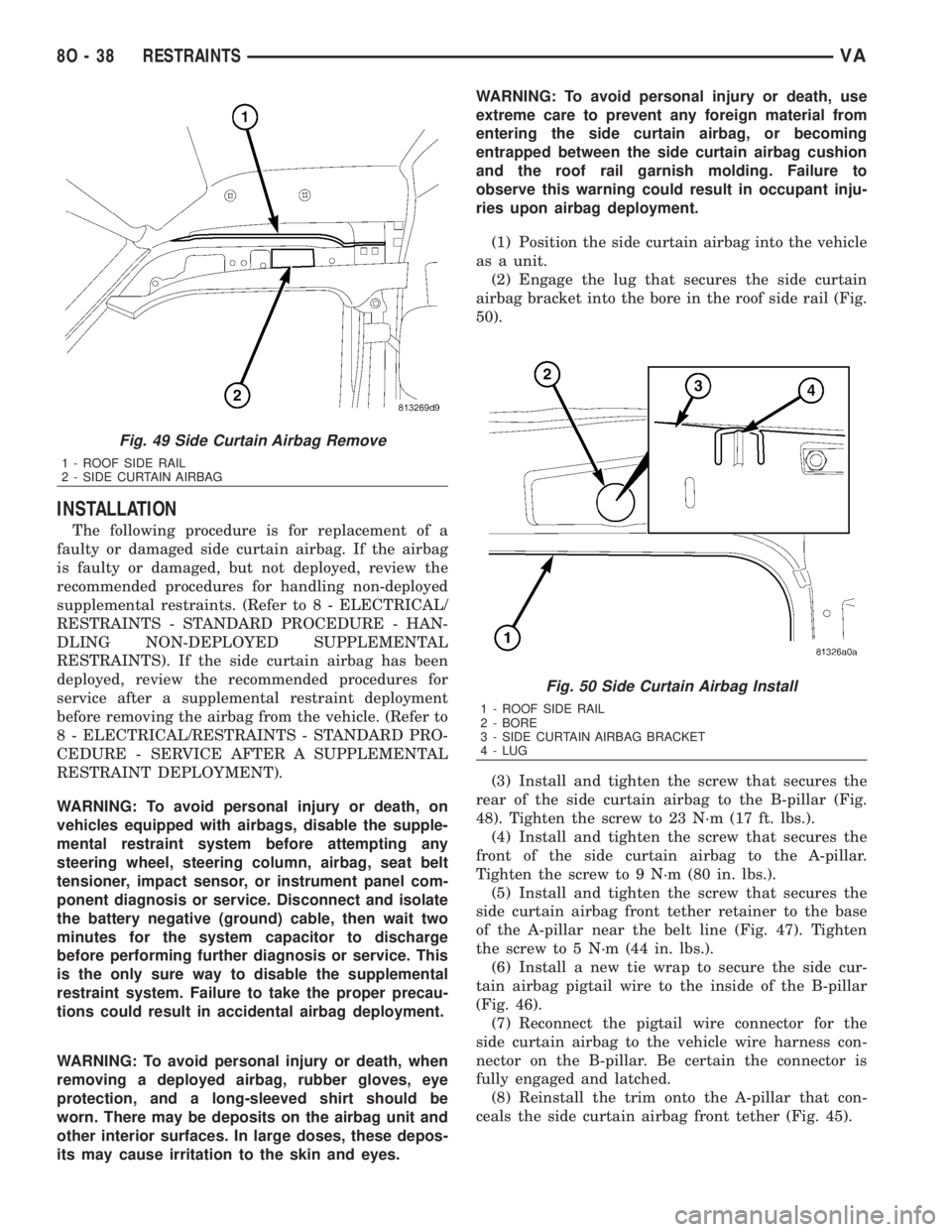
(2) Engage the lug that secures the side curtain
airbag bracket into the bore in the roof side rail (Fig.
50).
(3) Install and tighten the screw that secures the
rear of the side curtain airbag to the B-pillar (Fig.
48). Tighten the screw to 23 N´m (17 ft. lbs.).
(4) Install and tighten the screw that secures the
front of the side curtain airbag to the A-pillar.
Tighten the screw to 9 N´m (80 in. lbs.).
(5) Install and tighten the screw that secures the
side curtain airbag front tether retainer to the base
of the A-pillar near the belt line (Fig. 47). Tighten
the screw to 5 N´m (44 in. lbs.).
(6) Install a new tie wrap to secure the side cur-
tain airbag pigtail wire to the inside of the B-pillar
(Fig. 46).
(7) Reconnect the pigtail wire connector for the
side curtain airbag to the vehicle wire harness con-
nector on the B-pillar. Be certain the connector is
fully engaged and latched.
(8) Reinstall the trim onto the A-pillar that con-
ceals the side curtain airbag front tether (Fig. 45).
Fig. 49 Side Curtain Airbag Remove
1 - ROOF SIDE RAIL
2 - SIDE CURTAIN AIRBAG
Fig. 50 Side Curtain Airbag Install
1 - ROOF SIDE RAIL
2 - BORE
3 - SIDE CURTAIN AIRBAG BRACKET
4 - LUG
8O - 38 RESTRAINTSVA
Page 1030 of 2305
(9) Reinstall the grab handle onto the headliner.
(Refer to 23 - BODY/INTERIOR/ASSIST HANDLE -
INSTALLATION).
(10) Reinstall the trim onto the inside of the B-pil-
lar. (Refer to 23 - BODY/INTERIOR/B-PILLAR TRIM
- INSTALLATION).
(11) Reinstall the pinch welt to the front door
opening (Fig. 44).
(12) Do not reconnect the battery negative cable at
this time. The supplemental restraint system verifi-
cation test procedure should be performed following
service of any supplemental restraint system compo-
nent. (Refer to 8 - ELECTRICAL/RESTRAINTS -
STANDARD PROCEDURE - VERIFICATION TEST).
SIDE IMPACT SENSOR
DESCRIPTION
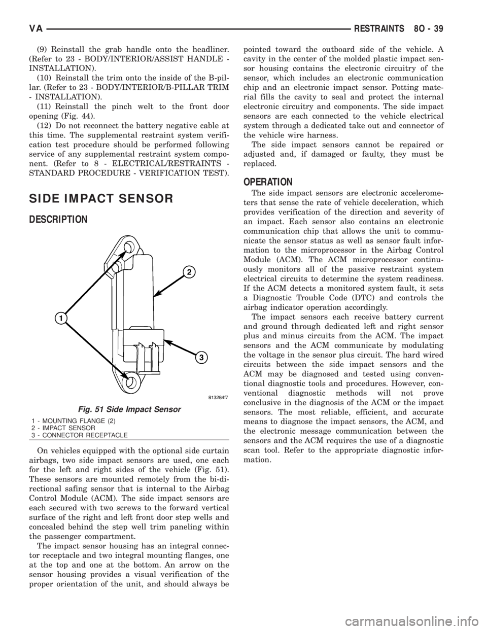
On vehicles equipped with the optional side curtain
airbags, two side impact sensors are used, one each
for the left and right sides of the vehicle (Fig. 51).
These sensors are mounted remotely from the bi-di-
rectional safing sensor that is internal to the Airbag
Control Module (ACM). The side impact sensors are
each secured with two screws to the forward vertical
surface of the right and left front door step wells and
concealed behind the step well trim paneling within
the passenger compartment.
The impact sensor housing has an integral connec-
tor receptacle and two integral mounting flanges, one
at the top and one at the bottom. An arrow on the
sensor housing provides a visual verification of the
proper orientation of the unit, and should always bepointed toward the outboard side of the vehicle. A
cavity in the center of the molded plastic impact sen-
sor housing contains the electronic circuitry of the
sensor, which includes an electronic communication
chip and an electronic impact sensor. Potting mate-
rial fills the cavity to seal and protect the internal
electronic circuitry and components. The side impact
sensors are each connected to the vehicle electrical
system through a dedicated take out and connector of
the vehicle wire harness.
The side impact sensors cannot be repaired or
adjusted and, if damaged or faulty, they must be
replaced.
OPERATION
The side impact sensors are electronic accelerome-
ters that sense the rate of vehicle deceleration, which
provides verification of the direction and severity of
an impact. Each sensor also contains an electronic
communication chip that allows the unit to commu-
nicate the sensor status as well as sensor fault infor-
mation to the microprocessor in the Airbag Control
Module (ACM). The ACM microprocessor continu-
ously monitors all of the passive restraint system
electrical circuits to determine the system readiness.
If the ACM detects a monitored system fault, it sets
a Diagnostic Trouble Code (DTC) and controls the
airbag indicator operation accordingly.
The impact sensors each receive battery current
and ground through dedicated left and right sensor
plus and minus circuits from the ACM. The impact
sensors and the ACM communicate by modulating
the voltage in the sensor plus circuit. The hard wired
circuits between the side impact sensors and the
ACM may be diagnosed and tested using conven-
tional diagnostic tools and procedures. However, con-
ventional diagnostic methods will not prove
conclusive in the diagnosis of the ACM or the impact
sensors. The most reliable, efficient, and accurate
means to diagnose the impact sensors, the ACM, and
the electronic message communication between the
sensors and the ACM requires the use of a diagnostic
scan tool. Refer to the appropriate diagnostic infor-
mation.
Fig. 51 Side Impact Sensor
1 - MOUNTING FLANGE (2)
2 - IMPACT SENSOR
3 - CONNECTOR RECEPTACLE
VARESTRAINTS 8O - 39
Page 1031 of 2305
REMOVAL
WARNING: To avoid personal injury or death, on
vehicles equipped with airbags, disable the supple-
mental restraint system before attempting any
steering wheel, steering column, airbag, seat belt
tensioner, impact sensor, or instrument panel com-
ponent diagnosis or service. Disconnect and isolate
the battery negative (ground) cable, then wait two
minutes for the system capacitor to discharge
before performing further diagnosis or service. This
is the only sure way to disable the supplemental
restraint system. Failure to take the proper precau-
tions could result in accidental airbag deployment.
WARNING: To avoid personal injury or death, never
strike or drop the side impact sensor, as it can
damage the impact sensor or affect its calibration.
The side impact sensor enables the system to
deploy the side curtain airbags. If an impact sensor
is accidentally dropped during service, the sensor
must be scrapped and replaced with a new unit.
Failure to observe this warning could result in acci-
dental, incomplete, or improper supplemental
restraint deployment.
(1) Disconnect and isolate the battery negative
cable. Wait two minutes for the system capacitor to
discharge before further service.
(2) Remove the trim paneling from the interior of
the front door step well. (Refer to 23 - BODY/INTE-
RIOR/STEPWELL SCUFF PADS - REMOVAL).
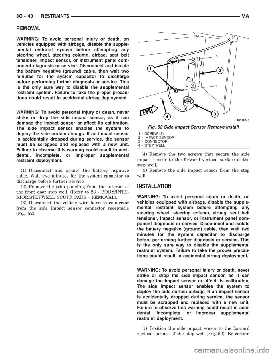
(3) Disconnect the vehicle wire harness connector
from the side impact sensor connector receptacle
(Fig. 52).(4) Remove the two screws that secure the side
impact sensor to the forward vertical surface of the
step well.
(5) Remove the side impact sensor from the step
well.
INSTALLATION
WARNING: To avoid personal injury or death, on
vehicles equipped with airbags, disable the supple-
mental restraint system before attempting any
steering wheel, steering column, airbag, seat belt
tensioner, impact sensor, or instrument panel com-
ponent diagnosis or service. Disconnect and isolate
the battery negative (ground) cable, then wait two
minutes for the system capacitor to discharge
before performing further diagnosis or service. This
is the only sure way to disable the supplemental
restraint system. Failure to take the proper precau-
tions could result in accidental airbag deployment.
WARNING: To avoid personal injury or death, never
strike or drop the side impact sensor, as it can
damage the impact sensor or affect its calibration.
The side impact sensor enables the system to
deploy the side curtain airbags. If an impact sensor
is accidentally dropped during service, the sensor
must be scrapped and replaced with a new unit.
Failure to observe this warning could result in acci-
dental, incomplete, or improper supplemental
restraint deployment.
(1) Position the side impact sensor to the forward
vertical surface of the step well (Fig. 52). Be certain
Fig. 52 Side Impact Sensor Remove/Install
1 - SCREW (2)
2 - IMPACT SENSOR
3 - CONNECTOR
4 - STEP WELL
8O - 40 RESTRAINTSVA
Page 1032 of 2305

that the arrow on the sensor housing is pointed
toward the outboard side of the vehicle.
(2) Install and tighten the two screws that secure
the side impact sensor to the step well.
(3) Reconnect the vehicle wire harness connector
for the side impact sensor to the sensor connector
receptacle.
(4) Reinstall the trim paneling to the interior of
the front door step well. (Refer to 23 - BODY/INTE-
RIOR/STEPWELL SCUFF PADS - INSTALLATION).
(5) Do not reconnect the battery negative cable at
this time. The supplemental restraint system verifi-
cation test procedure should be performed following
service of any supplemental restraint system compo-
nent. (Refer to 8 - ELECTRICAL/RESTRAINTS -
STANDARD PROCEDURE - VERIFICATION TEST).
VARESTRAINTS 8O - 41
Page 1038 of 2305
VEHICLE THEFT SECURITY
TABLE OF CONTENTS
page page
VEHICLE THEFT SECURITY
DESCRIPTION..........................1
OPERATION............................1
DIAGNOSIS AND TESTING - VEHICLE THEFT
SECURITY............................1
INTRUSION SENSOR
REMOVAL.............................1
INSTALLATION..........................2
SECURITY SYSTEM MODULE
REMOVAL.............................2
INSTALLATION..........................2SENTRY KEY REMOTE ENTRY MODULE
DESCRIPTION..........................2
OPERATION............................3
REMOVAL.............................3
INSTALLATION..........................4
SIREN
REMOVAL.............................4
INSTALLATION..........................4
TRANSPONDER KEY
DESCRIPTION..........................5
OPERATION............................5
VEHICLE THEFT SECURITY
DESCRIPTION
A vehicle theft alarm with a battery powered siren
is available as an option and includes interior moni-
toring, anti-tow away protection and rear window
monitoring based on the heater wires. The alarm is
automatically activated when the central locking sys-
tem is operated.
The alarm will sound when any of the following
occur:
²A door is opened
²A door is unlocked from inside the vehicle
²The hood is opened
²The vehicle is raised at the front or rear
²The trailer wire harness is disconnected
²Movements inside the vehicle
²The central locking is unlocked by a key at any
other door than the driver's door
The alarm is functional about 30 seconds after the
vehicle is locked using the RKE transmitter or the
key in the driver's door. Activation is indicated by the
indicator lights flashing three times and the warning
lamp flashing in the switch. If persons or animals
remain in the locked vehicle, the operator should
switch off the interior monitor to avoid a false alarm.
OPERATION
The anti-theft alarm is activated/deactivated by
locking/unlocking the vehicle with the remote trans-
mitter or with the key at the driver's door. The key
must be held in the locking position for more than
two seconds. Activation is indicated by the turn sig-
nal lights flashing once. Unlocking the vehicle at one
of the other doors will trigger an alarm.
The interior monitoring system included in the
anti-theft alarm is based on ultrasonics and triggersan alarm if an object intrudes the interior of the
vehicle or if any movement is detected inside the
vehicle. For proper and effective protection, all win-
dows and the sunroof must be closed.
To switch off the interior monitoring system and /
or the anti-tow away protection, a switch with LED
indicator light is provided in the switch panel. An
alarm button enables the operator to trigger an
alarm manually and to lock all doors if they are
closed. Triggering an alarm makes the horn sound
and the turn signals flash until the alarm is switched
off.
The anti-theft alarm control unit includes a gradi-
ent indicator as anti-tow away protection. The gradi-
ent indicator triggers an audible and visual alarm if
the vehicle is lifted (to tow away or to remove the
wheels). The alarm remains effective even if the bat-
tery is disconnected as the horn is powered by its
own battery. The interior monitoring system should
be switched off if people and/or animals are left in
the vehicle.
DIAGNOSIS AND TESTING - VEHICLE THEFT
SECURITY
Any diagnosis of the Vehicle Theft Security
system should begin with the use of a diagnos-
tic scan tool. Refer to the appropriate diagnos-
tic information.
INTRUSION SENSOR
REMOVAL
(1) Disconnect and isolate the battery negative
cable.
(2) Insert the tip of a small flat-bladed screwdriver
into the notch on one edge of the dome lamp/intru-
sion sensor unit housing to depress the retainer clip
VAVEHICLE THEFT SECURITY 8Q - 1
Page 1039 of 2305
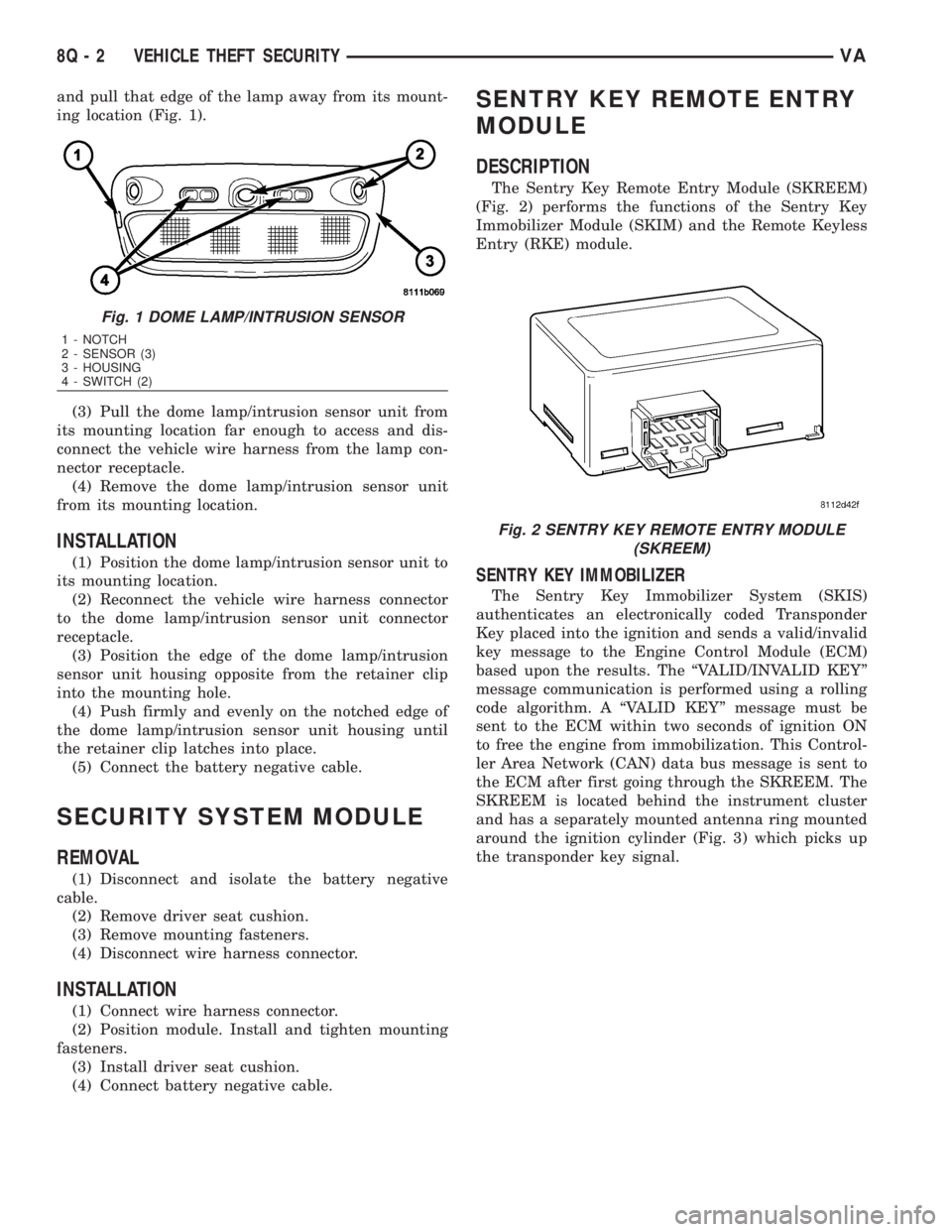
and pull that edge of the lamp away from its mount-
ing location (Fig. 1).
(3) Pull the dome lamp/intrusion sensor unit from
its mounting location far enough to access and dis-
connect the vehicle wire harness from the lamp con-
nector receptacle.
(4) Remove the dome lamp/intrusion sensor unit
from its mounting location.
INSTALLATION
(1) Position the dome lamp/intrusion sensor unit to
its mounting location.
(2) Reconnect the vehicle wire harness connector
to the dome lamp/intrusion sensor unit connector
receptacle.
(3) Position the edge of the dome lamp/intrusion
sensor unit housing opposite from the retainer clip
into the mounting hole.
(4) Push firmly and evenly on the notched edge of
the dome lamp/intrusion sensor unit housing until
the retainer clip latches into place.
(5) Connect the battery negative cable.
SECURITY SYSTEM MODULE
REMOVAL
(1) Disconnect and isolate the battery negative
cable.
(2) Remove driver seat cushion.
(3) Remove mounting fasteners.
(4) Disconnect wire harness connector.
INSTALLATION
(1) Connect wire harness connector.
(2) Position module. Install and tighten mounting
fasteners.
(3) Install driver seat cushion.
(4) Connect battery negative cable.
SENTRY KEY REMOTE ENTRY
MODULE
DESCRIPTION
The Sentry Key Remote Entry Module (SKREEM)
(Fig. 2) performs the functions of the Sentry Key
Immobilizer Module (SKIM) and the Remote Keyless
Entry (RKE) module.
SENTRY KEY IMMOBILIZER
The Sentry Key Immobilizer System (SKIS)
authenticates an electronically coded Transponder
Key placed into the ignition and sends a valid/invalid
key message to the Engine Control Module (ECM)
based upon the results. The ªVALID/INVALID KEYº
message communication is performed using a rolling
code algorithm. A ªVALID KEYº message must be
sent to the ECM within two seconds of ignition ON
to free the engine from immobilization. This Control-
ler Area Network (CAN) data bus message is sent to
the ECM after first going through the SKREEM. The
SKREEM is located behind the instrument cluster
and has a separately mounted antenna ring mounted
around the ignition cylinder (Fig. 3) which picks up
the transponder key signal.
Fig. 1 DOME LAMP/INTRUSION SENSOR
1 - NOTCH
2 - SENSOR (3)
3 - HOUSING
4 - SWITCH (2)
Fig. 2 SENTRY KEY REMOTE ENTRY MODULE
(SKREEM)
8Q - 2 VEHICLE THEFT SECURITYVA
Page 1044 of 2305

WIPERS / WASHERS
TABLE OF CONTENTS
page page
WIPERS/WASHERS
DESCRIPTION..........................2
OPERATION............................3
DIAGNOSIS AND TESTING - WIPER &
WASHER SYSTEM.....................6
CLEANING - WIPER & WASHER SYSTEM.....9
INSPECTION - WIPER & WASHER SYSTEM . . 10
CHECK VALVE
DESCRIPTION.........................11
OPERATION...........................11
REMOVAL.............................11
INSTALLATION.........................11
RAIN SENSOR
DESCRIPTION.........................12
OPERATION...........................12
STANDARD PROCEDURE
RAIN SENSOR BRACKET REPLACEMENT . . 12
REMOVAL.............................14
INSTALLATION.........................14
RAIN SENSOR CONTROL MODULE
DESCRIPTION.........................15
OPERATION...........................15
REMOVAL.............................15
INSTALLATION.........................16
WASHER FLUID LEVEL SWITCH
DESCRIPTION.........................16
OPERATION...........................16
WASHER HOSES/TUBES
DESCRIPTION.........................18
OPERATION...........................18
WASHER NOZZLE
DESCRIPTION.........................18
OPERATION...........................19
REMOVAL.............................19
INSTALLATION.........................19WASHER PUMP/MOTOR
DESCRIPTION.........................19
OPERATION...........................20
REMOVAL.............................20
INSTALLATION.........................20
WASHER RESERVOIR
DESCRIPTION.........................21
OPERATION...........................21
REMOVAL.............................21
INSTALLATION.........................22
WIPER ARM
DESCRIPTION.........................23
OPERATION...........................24
REMOVAL.............................24
INSTALLATION.........................24
WIPER BLADE
DESCRIPTION.........................26
OPERATION...........................26
REMOVAL.............................26
INSTALLATION.........................27
WIPER LINKAGE
DESCRIPTION.........................28
OPERATION...........................28
REMOVAL.............................28
INSTALLATION.........................31
WIPER MOTOR
DESCRIPTION.........................31
OPERATION...........................32
REMOVAL.............................32
INSTALLATION.........................33
WIPER RELAY
DESCRIPTION.........................34
OPERATION...........................34
REMOVAL.............................35
INSTALLATION.........................35
VAWIPERS/WASHERS 8R - 1
Page 1045 of 2305
WIPERS/WASHERS
DESCRIPTION
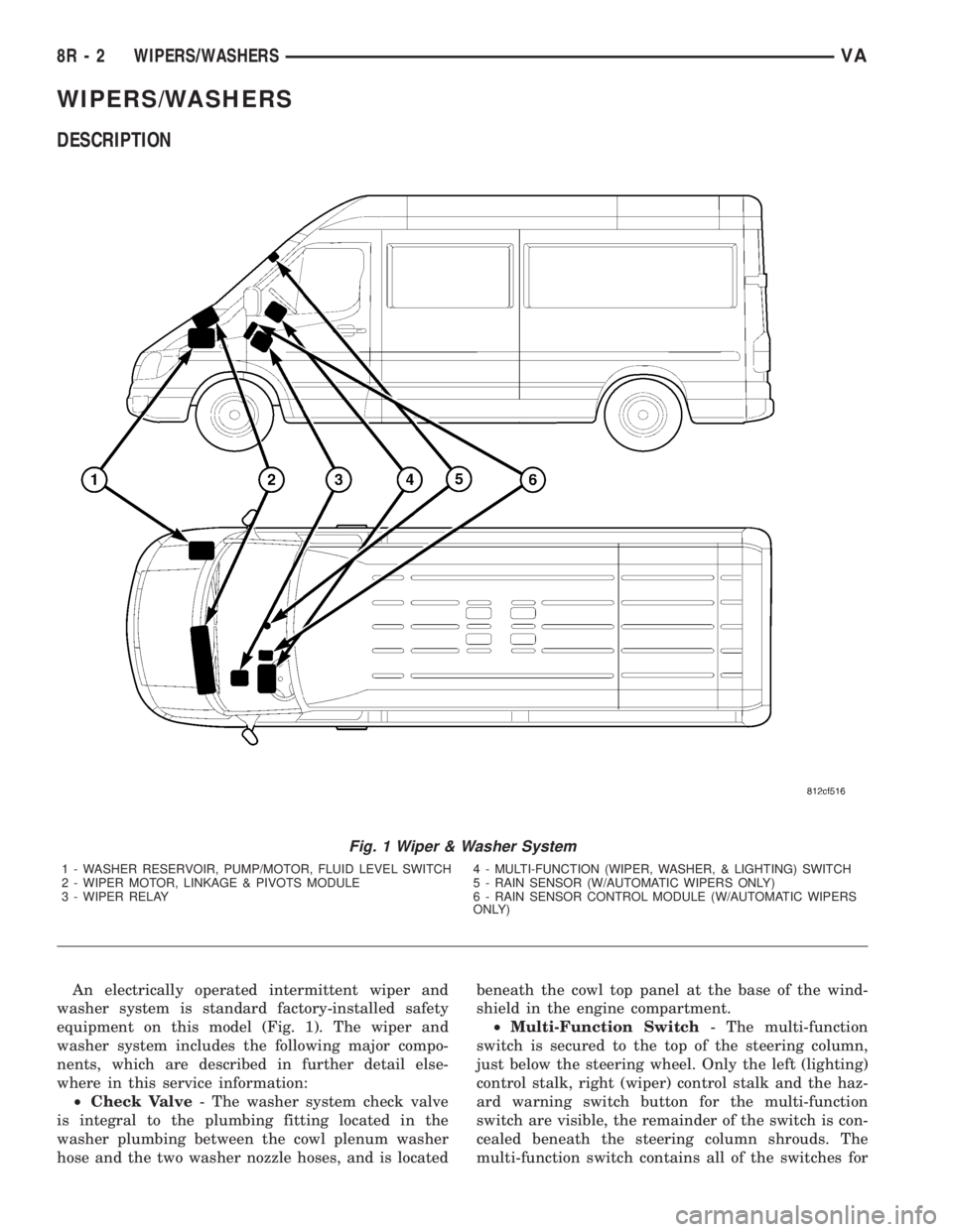
An electrically operated intermittent wiper and
washer system is standard factory-installed safety
equipment on this model (Fig. 1). The wiper and
washer system includes the following major compo-
nents, which are described in further detail else-
where in this service information:
²Check Valve- The washer system check valve
is integral to the plumbing fitting located in the
washer plumbing between the cowl plenum washer
hose and the two washer nozzle hoses, and is locatedbeneath the cowl top panel at the base of the wind-
shield in the engine compartment.
²Multi-Function Switch- The multi-function
switch is secured to the top of the steering column,
just below the steering wheel. Only the left (lighting)
control stalk, right (wiper) control stalk and the haz-
ard warning switch button for the multi-function
switch are visible, the remainder of the switch is con-
cealed beneath the steering column shrouds. The
multi-function switch contains all of the switches for
Fig. 1 Wiper & Washer System
1 - WASHER RESERVOIR, PUMP/MOTOR, FLUID LEVEL SWITCH 4 - MULTI-FUNCTION (WIPER, WASHER, & LIGHTING) SWITCH
2 - WIPER MOTOR, LINKAGE & PIVOTS MODULE 5 - RAIN SENSOR (W/AUTOMATIC WIPERS ONLY)
3 - WIPER RELAY 6 - RAIN SENSOR CONTROL MODULE (W/AUTOMATIC WIPERS
ONLY)
8R - 2 WIPERS/WASHERSVA