2006 MERCEDES-BENZ SPRINTER sensor
[x] Cancel search: sensorPage 1046 of 2305
both the wiper and washer systems. (Refer to 8 -
ELECTRICAL/LAMPS/LIGHTING - EXTERIOR/
MULTI-FUNCTION SWITCH - DESCRIPTION)
²Rain Sensor- Vehicles equipped with an
optional automatic wiper feature have an electronic
rain sensor concealed within the base of the rear
view mirror unit on the inside of the laminated wind-
shield glass.
²Rain Sensor Control Module- Vehicles
equipped with an optional automatic wiper feature
have an electronic rain sensor control module located
under the lower instrument panel above the acceler-
ator pedal in the passenger compartment of the vehi-
cle.
²Washer Fluid Level Switch- The optional
washer fluid level switch is integral to a unique ver-
sion of the washer pump/motor unit, which is located
in a dedicated hole on the top of the sump area near
the back of the windshield washer reservoir on the
right front fender wheel house in the engine com-
partment.
²Washer Nozzle- A single washer nozzle with
three separate orifices is secured with integral snap
features to each wiper arm. The hoses for the washer
nozzles are concealed beneath a molded plastic guide
on the underside of each wiper arm and routed to the
engine compartment through unique molded plastic
elbow fittings located near each wiper pivot at the
base of the windshield.
²Washer Pump/Motor- Two different washer
pump/motor units are available for this model. One
version has an integral washer fluid level switch that
provides a hard wired input to the instrument cluster
for control of the optional washer fluid indicator. The
washer pump/motor unit is located in a dedicated
hole on the top of the sump area near the back of the
windshield washer reservoir on the right front fender
wheel house in the engine compartment.
²Washer Reservoir- The washer reservoir is
located on the right front fender wheel house in the
engine compartment. The washer reservoir filler is
accessed from the right front corner of the engine
compartment.
²Wiper Arm- The two unequal length wiper
arms are secured to the two wiper pivots, which
extend through the cowl panel near the base of the
windshield. The longer arm is installed on the left
(driver) side of the windshield.
²Wiper Blade- The two unequal length wiper
blades are secured to the two wiper arms, and are
parked on the glass near the bottom of the wind-
shield when the wiper system is not in operation.
The longer blade is installed on the left (driver) side
of the windshield.
²Wiper Linkage- The wiper pivots are the only
visible components of the wiper linkage. The remain-
der of the linkage is concealed within the engine
compartment just behind the hood opening. Thewiper linkage module includes the two wiper drive
links, the wiper motor crank arm, the two wiper piv-
ots, and the linkage and motor mounting bracket.
²Wiper Motor- The wiper motor is secured to
the wiper linkage module bracket on the underside of
the cowl panel within the engine compartment. The
wiper motor output shaft and crank arm extend
through a clearance hole in the mounting bracket,
where they are connected to a crank arm that drives
the wiper linkage.
²Wiper Relay- The wiper relay is located in a
dedicated receptacle on the lower left surface of the
fuse block underneath the steering column behind
the fuse access panel and the steering column open-
ing panel. The wiper relay is a passive component on
vehicles equipped with the optional automatic wiper
system.
²Wiper, Turn Signals, Engine Start Control
Module- The wiper, turn signals and engine start
control module is integral to the fuse block located
underneath the steering column. The fuse block is
concealed behind the fuse access panel and the steer-
ing column opening panel, where it is secured with
screws to the steering column. The wiper system
functions of this module are passive on vehicles
equipped with the optional automatic wiper system.
Hard wired circuitry connects the wiper and
washer system components to the electrical system of
the vehicle. These hard wired circuits are integral to
several wire harnesses, which are routed throughout
the vehicle and retained by many different methods.
These circuits may be connected to each other, to the
vehicle electrical system and to the wiper and washer
system components through the use of a combination
of soldered splices, splice block connectors, and many
different types of wire harness terminal connectors
and insulators. Refer to the appropriate wiring infor-
mation. The wiring information includes wiring dia-
grams, proper wire and connector repair procedures,
further details on wire harness routing and reten-
tion, as well as pin-out and location views for the
various wire harness connectors, splices and grounds.
OPERATION
The wiper and washer system is designed to pro-
vide the vehicle operator with a convenient, safe, and
reliable means of maintaining visibility through the
windshield glass. The various components of this sys-
tem are designed to convert electrical energy pro-
duced by the vehicle electrical system into the
mechanical action of the wiper blades to wipe the
outside surface of the glass, as well as into the
hydraulic action of the washer system to apply
washer fluid stored in an on-board reservoir to the
area of the glass to be wiped. When combined, these
components provide the means to effectively main-
tain clear visibility for the vehicle operator by remov-
ing excess accumulations of rain, snow, bugs, mud, or
VAWIPERS/WASHERS 8R - 3
Page 1048 of 2305
is closed with the wiper system turned Off, the inter-
mittent wipe logic circuitry operates the wiper motor
in the same manner as it does to provide the inter-
mittent wipe mode operation. After the state of the
washer switch changes to open, the intermittent wipe
logic circuitry monitors the wiper motor through the
wiper on-off relay output circuit, which allows it to
monitor the number of wiper blade sweeps. After the
appropriate number of wiper sweeps the intermittent
wipe logic circuitry operates the wiper motor to
return the wipers to their park position, then de-en-
ergizes the wiper relay.
AUTOMATIC WIPE SYSTEM
When the ignition switch is in the On position, bat-
tery current from a fuse in the fuse block underneath
the steering column is provided through a fused igni-
tion switch output (run-start) circuit to the rain sen-
sor control module under the instrument panel, to
the rain sensor within the base of the inside rear
view mirror on the windshield, and to the multi-func-
tion switch. The internal circuitry of the multi-func-
tion switch provides direct hard wired battery
current outputs to the rain sensor control module to
indicate the selected wiper operating mode. The con-
trol module logic monitors the inputs from the multi-
function switch as well as from the rain sensor and
the wiper motor park switch in order to provide the
outputs necessary to operate the wiper motor and the
washer pump motor as requested.
When the automatic wipe position is selected with
the multi-function switch control stalk, the rain sen-
sor control module logic circuitry responds by provid-
ing an acknowledgment sweep of the wipers. The
rain sensor calculates the correct wiper speed and
wiper sweep intervals required to remove the mois-
ture detected on the windshield glass and provides
this input to the rain sensor control module. The con-
trol module then energizes and de-energizes the
wiper motor automatically. The automatic wipe logic
will also provide a wipe-after-wash feature to clear
washer fluid that is directed onto the windshield
when the washer system is utilized.
When the Off position of the multi-function switch
wiper control stalk is selected, one of two events is
possible. The event that will occur depends upon the
position of the wiper blades on the windshield at the
moment that the Off position is selected. If the wiper
blades are in the down position on the windshield
when the Off position is selected, the park switch
that is integral to the wiper motor is closed to
ground, and the rain sensor control module logic cir-
cuit de-energizes the wiper motor. If the wiper blades
are not in the down position at the moment the Off
position is selected, the park switch is an open cir-
cuit. The control module logic circuit directs battery
current to the low speed brush of the wiper motor,
which causes the wiper motor to continue runninguntil the wiper blades are in the down position on
the windshield and the park switch is again closed to
ground.
When the Wash position of the control knob on the
right control stalk of the multi-function switch is
selected with the wiper system turned Off, the rain
sensor control module logic circuitry operates the
wiper motor in the same manner as it does to provide
the automatic wipe mode operation. After the state of
the washer switch changes to open the control mod-
ule monitors the wiper motor through the wiper park
switch sense circuit, which allows it to monitor the
number of wiper blade sweeps. After the appropriate
number of wiper sweeps the control module operates
the wiper motor to return the wipers to their park
position, then de-energizes the wiper motor.
OPERATING MODES
The components of the wiper and washer system
are designed to provide the following operating
modes:
²Automatic Wipe Mode- On vehicles so
equipped, the internal circuitry of the multi-function
switch, the rain sensor control module and the rain
sensor work in concert to provide wiper system oper-
ation automatically whenever moisture is detected on
the windshield glass.
²Continuous Wipe Mode- The two-speed wiper
motor, the internal circuitry of the multi-function
switch, and the wiper system logic circuits work in
concert to provide two continuous wipe cycles, low
speed or high speed.
²Intermittent Wipe Mode- On vehicles so
equipped, the internal circuitry of the multi-function
switch, the intermittent wipe circuitry of the wiper,
turn signals and engine start control module in the
fuse block, and the wiper relay work in concert to
provide an intermittent wipe mode with a single,
fixed delay interval.
²Pulse Wipe Mode- The internal circuitry of
the multi-function switch and the wiper system logic
circuits work in concert to provide a pulse wipe mode
that will allow the wiper motor to be operated for a
single, complete wipe cycle.
²Washer Mode- When the washer system is
activated with the multi-function switch while the
wiper system is operating, washer fluid will be dis-
pensed onto the windshield glass through the washer
nozzles for as long as the washer pump/motor is
energized.
²Wipe-After-Wash Mode- The wiper system
logic circuitry provides a wipe-after-wash feature. If
the wipers are turned Off, this feature will operate
the washer pump/motor and the wipers for as long as
the washer system is activated, then provide several
additional wipe cycles after the washer system is
deactivated before parking the wiper blades near the
base of the windshield.
VAWIPERS/WASHERS 8R - 5
Page 1049 of 2305
DIAGNOSIS AND TESTING - WIPER &
WASHER SYSTEM
If the wiper motor operates, but the wipers do not
move on the windshield, replace the faulty wiper
linkage module. If the washer pump/motor operates,
but no washer fluid is dispensed on the glass; or, if
the wipers operate, but chatter, lift, or do not clear
the glass, clean and inspect the wiper and washer
system components as required. (Refer to 8 - ELEC-
TRICAL/WIPERS/WASHERS - CLEANING) and
(Refer to 8 - ELECTRICAL/WIPERS/WASHERS -
INSPECTION). For diagnosis and testing of the
multi-function switch (Refer to 8 - ELECTRICAL/
LAMPS/LIGHTING - EXTERIOR/MULTI-FUNC-
TION SWITCH - DIAGNOSIS AND TESTING).
Refer to the appropriate wiring information. The wir-
ing information includes wiring diagrams, proper
wire and connector repair procedures, details of wire
harness routing and retention, connector pin-out
information and location views for the various wire
harness connectors, splices and grounds.
The hard wired circuits and components of the
wiper and washer system may be diagnosed andtested using conventional diagnostic tools and proce-
dures. However, conventional diagnostic methods
may not prove conclusive in the diagnosis of the
intermittent wipe logic circuitry contained within the
fuse block underneath the steering column, the rain
sensor within the base of the rear view mirror on the
windshield, or the rain sensor control module under
the instrument panel.
WARNING: To avoid personal injury or death, on
vehicles equipped with airbags, disable the supple-
mental restraint system before attempting any
steering wheel, steering column, airbag, seat belt
tensioner, or instrument panel component diagno-
sis or service. Disconnect and isolate the battery
negative (ground) cable, then wait two minutes for
the system capacitor to discharge before perform-
ing further diagnosis or service. This is the only
sure way to disable the supplemental restraint sys-
tem. Failure to take the proper precautions could
result in accidental airbag deployment.
INTERMITTENT WIPER SYSTEM
CONDITION POSSIBLE CAUSES CORRECTION
WIPERS INOPERATIVE IN
ALL SWITCH POSITIONS1. Faulty or missing fuse. 1. Test and replace the fuse as required.
2. Faulty wiper motor ground circuit. 2. Test and repair the open ground circuit
as required.
3. Faulty multi-function switch feed
circuit.3. Test and repair the open fused ignition
switch output circuit between the fuse and
the multi-function switch as required.
4. Faulty multi-function switch. 4. Test and replace the multi-function
switch as required.
5. Faulty wiper motor. 5. Test and replace the wiper motor as
required.
WIPERS INOPERATIVE IN
INTERMITTENT POSITION
AND NO WIPE AFTER
WASH FEATURE1. Faulty wiper relay. 1. Test and replace the wiper relay as re-
quired.
2. Faulty multi-function switch. 2. Test and replace the multi-function
switch as required.
3. Faulty intermittent wipe logic cir-
cuit.3. Replace the steering column fuse block
as required.
WIPERS INOPERATIVE IN
LOW POSITION AND NO
PULSE FEATURE1. Faulty low speed circuit. 1. Test and repair the open low speed cir-
cuit between the multi-function switch and
the wiper motor as required.
2. Faulty multi-function switch. 2. Test and replace the multi-function
switch as required.
3. Faulty wiper low speed brush. 3. Test and replace the wiper motor as
required.
8R - 6 WIPERS/WASHERSVA
Page 1050 of 2305
CONDITION POSSIBLE CAUSES CORRECTION
WIPERS INOPERATIVE IN
HIGH POSITION1. Faulty high speed circuit. 1. Test and repair the open high speed
circuit between the multi-function switch
and the wiper motor as required.
2. Faulty multi-function switch. 2. Test and replace the multi-function
switch as required.
3. Faulty wiper high speed brush. 3. Test and replace the wiper motor as
required.
WIPERS DO NOT PARK
AFTER OPERATING1. Faulty motor feed circuit. 1. Test and repair the open fused ignition
switch output circuit to the wiper motor as
required.
2. Faulty park switch output circuit. 2. Test and repair the open or shorted cir-
cuit between the wiper park switch and
the wiper relay as required.
3. Faulty wiper relay. 3. Test and replace the wiper relay as re-
quired.
4. Faulty park switch. 4. Test and replace the wiper motor as
required.
WASHERS INOPERATIVE 1. Faulty washer pump ground cir-
cuit.1. Test and repair the open ground circuit
as required.
2. Faulty washer pump feed circuit. 2. Test and repair the open circuit be-
tween the multi-function switch and the
washer pump as required.
3. Faulty washer pump motor. 3. Test and replace the washer pump as
required.
4. Faulty muli-function switch. 4. Test and replace the multi-function
switch as required.
AUTOMATIC WIPER SYSTEM
CONDITION POSSIBLE CAUSES CORRECTION
WIPERS INOPERATIVE IN
ALL SWITCH POSITIONS1. Faulty or missing fuse. 1. Test and replace the fuse as required.
2. Faulty wiper motor ground circuit. 2. Test and repair the open ground circuit
as required.
3. Faulty wiper motor. 3. Test and replace the wiper motor as
required.
4. Faulty multi-function switch feed
circuit.4. Test and repair the open fused ignition
switch output circuit between the fuse and
the multi-function switch as required.
5. Faulty multi-function switch. 5. Test and replace the multi-function
switch as required.
6. Faulty rain sensor control module
ground circuit.6. Test and repair the open ground circuit
as required.
7. Faulty rain sensor control module
feed circuit.7. Test and repair the open fused ignition
switch output circuit between the fuse and
the rain sensor control module as re-
quired.
8. Faulty rain sensor control mod-
ule.8. Test and replace the rain sensor control
module as required.
VAWIPERS/WASHERS 8R - 7
Page 1051 of 2305
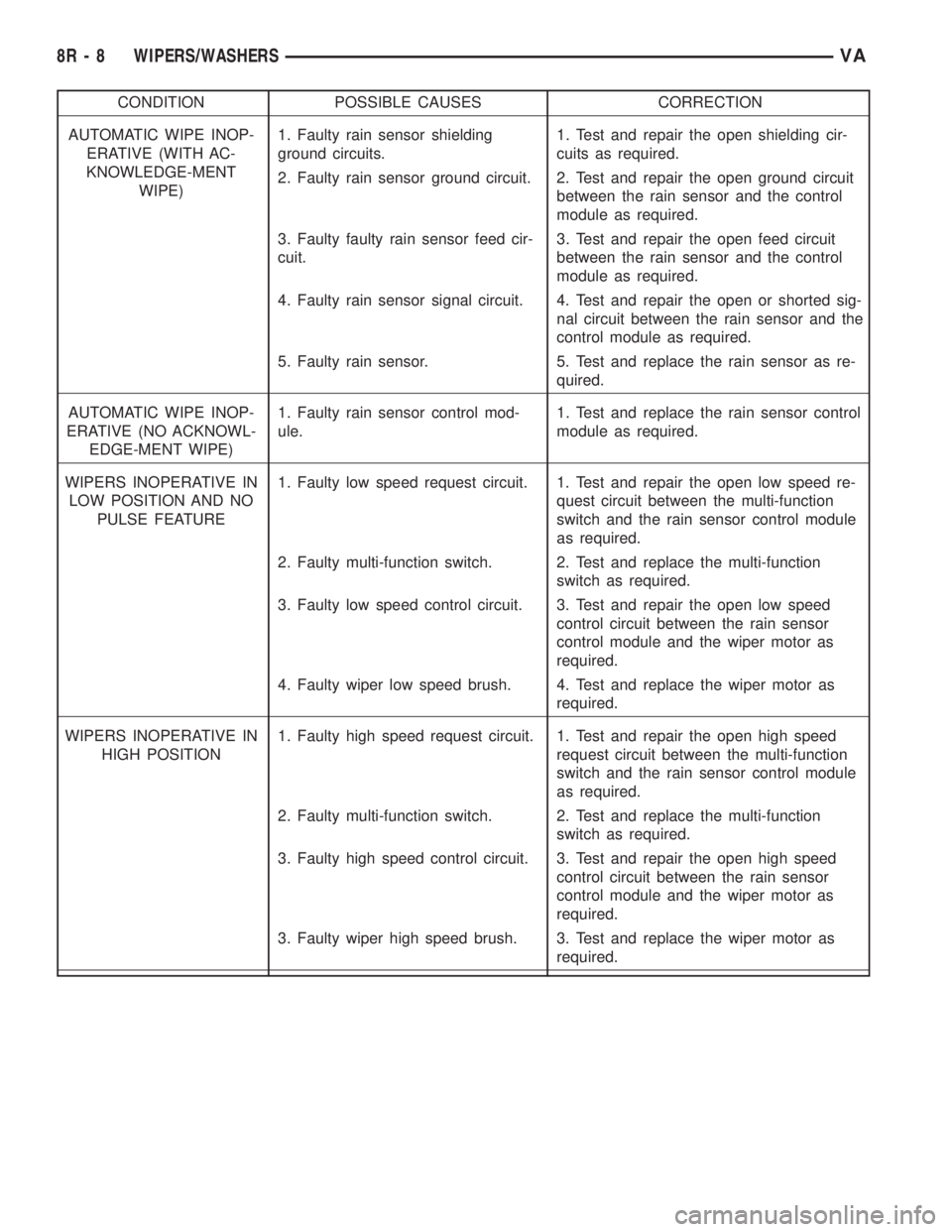
CONDITION POSSIBLE CAUSES CORRECTION
AUTOMATIC WIPE INOP-
ERATIVE (WITH AC-
KNOWLEDGE-MENT
WIPE)1. Faulty rain sensor shielding
ground circuits.1. Test and repair the open shielding cir-
cuits as required.
2. Faulty rain sensor ground circuit. 2. Test and repair the open ground circuit
between the rain sensor and the control
module as required.
3. Faulty faulty rain sensor feed cir-
cuit.3. Test and repair the open feed circuit
between the rain sensor and the control
module as required.
4. Faulty rain sensor signal circuit. 4. Test and repair the open or shorted sig-
nal circuit between the rain sensor and the
control module as required.
5. Faulty rain sensor. 5. Test and replace the rain sensor as re-
quired.
AUTOMATIC WIPE INOP-
ERATIVE (NO ACKNOWL-
EDGE-MENT WIPE)1. Faulty rain sensor control mod-
ule.1. Test and replace the rain sensor control
module as required.
WIPERS INOPERATIVE IN
LOW POSITION AND NO
PULSE FEATURE1. Faulty low speed request circuit. 1. Test and repair the open low speed re-
quest circuit between the multi-function
switch and the rain sensor control module
as required.
2. Faulty multi-function switch. 2. Test and replace the multi-function
switch as required.
3. Faulty low speed control circuit. 3. Test and repair the open low speed
control circuit between the rain sensor
control module and the wiper motor as
required.
4. Faulty wiper low speed brush. 4. Test and replace the wiper motor as
required.
WIPERS INOPERATIVE IN
HIGH POSITION1. Faulty high speed request circuit. 1. Test and repair the open high speed
request circuit between the multi-function
switch and the rain sensor control module
as required.
2. Faulty multi-function switch. 2. Test and replace the multi-function
switch as required.
3. Faulty high speed control circuit. 3. Test and repair the open high speed
control circuit between the rain sensor
control module and the wiper motor as
required.
3. Faulty wiper high speed brush. 3. Test and replace the wiper motor as
required.
8R - 8 WIPERS/WASHERSVA
Page 1052 of 2305
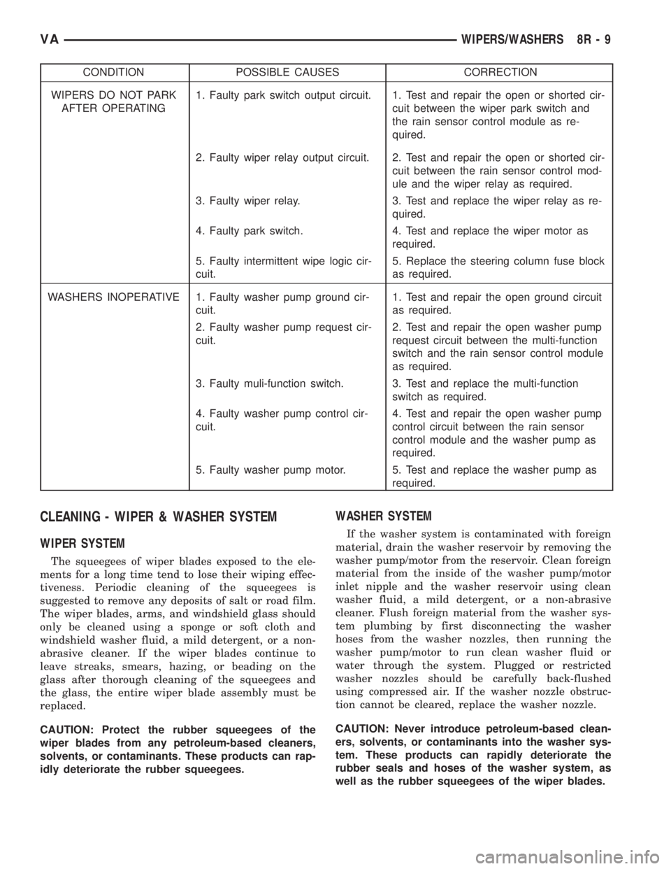
CONDITION POSSIBLE CAUSES CORRECTION
WIPERS DO NOT PARK
AFTER OPERATING1. Faulty park switch output circuit. 1. Test and repair the open or shorted cir-
cuit between the wiper park switch and
the rain sensor control module as re-
quired.
2. Faulty wiper relay output circuit. 2. Test and repair the open or shorted cir-
cuit between the rain sensor control mod-
ule and the wiper relay as required.
3. Faulty wiper relay. 3. Test and replace the wiper relay as re-
quired.
4. Faulty park switch. 4. Test and replace the wiper motor as
required.
5. Faulty intermittent wipe logic cir-
cuit.5. Replace the steering column fuse block
as required.
WASHERS INOPERATIVE 1. Faulty washer pump ground cir-
cuit.1. Test and repair the open ground circuit
as required.
2. Faulty washer pump request cir-
cuit.2. Test and repair the open washer pump
request circuit between the multi-function
switch and the rain sensor control module
as required.
3. Faulty muli-function switch. 3. Test and replace the multi-function
switch as required.
4. Faulty washer pump control cir-
cuit.4. Test and repair the open washer pump
control circuit between the rain sensor
control module and the washer pump as
required.
5. Faulty washer pump motor. 5. Test and replace the washer pump as
required.
CLEANING - WIPER & WASHER SYSTEM
WIPER SYSTEM
The squeegees of wiper blades exposed to the ele-
ments for a long time tend to lose their wiping effec-
tiveness. Periodic cleaning of the squeegees is
suggested to remove any deposits of salt or road film.
The wiper blades, arms, and windshield glass should
only be cleaned using a sponge or soft cloth and
windshield washer fluid, a mild detergent, or a non-
abrasive cleaner. If the wiper blades continue to
leave streaks, smears, hazing, or beading on the
glass after thorough cleaning of the squeegees and
the glass, the entire wiper blade assembly must be
replaced.
CAUTION: Protect the rubber squeegees of the
wiper blades from any petroleum-based cleaners,
solvents, or contaminants. These products can rap-
idly deteriorate the rubber squeegees.
WASHER SYSTEM
If the washer system is contaminated with foreign
material, drain the washer reservoir by removing the
washer pump/motor from the reservoir. Clean foreign
material from the inside of the washer pump/motor
inlet nipple and the washer reservoir using clean
washer fluid, a mild detergent, or a non-abrasive
cleaner. Flush foreign material from the washer sys-
tem plumbing by first disconnecting the washer
hoses from the washer nozzles, then running the
washer pump/motor to run clean washer fluid or
water through the system. Plugged or restricted
washer nozzles should be carefully back-flushed
using compressed air. If the washer nozzle obstruc-
tion cannot be cleared, replace the washer nozzle.
CAUTION: Never introduce petroleum-based clean-
ers, solvents, or contaminants into the washer sys-
tem. These products can rapidly deteriorate the
rubber seals and hoses of the washer system, as
well as the rubber squeegees of the wiper blades.
VAWIPERS/WASHERS 8R - 9
Page 1055 of 2305
RAIN SENSOR
DESCRIPTION
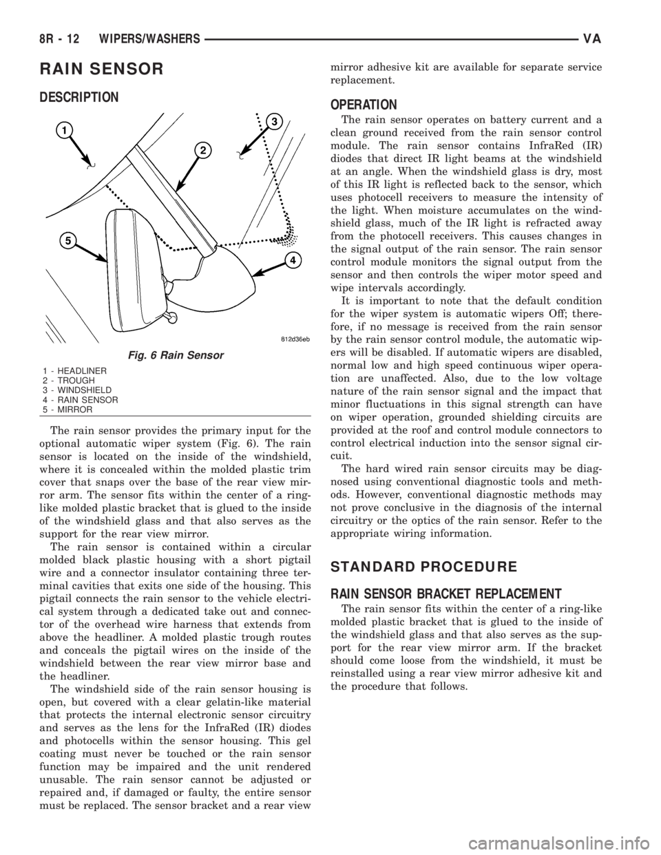
The rain sensor provides the primary input for the
optional automatic wiper system (Fig. 6). The rain
sensor is located on the inside of the windshield,
where it is concealed within the molded plastic trim
cover that snaps over the base of the rear view mir-
ror arm. The sensor fits within the center of a ring-
like molded plastic bracket that is glued to the inside
of the windshield glass and that also serves as the
support for the rear view mirror.
The rain sensor is contained within a circular
molded black plastic housing with a short pigtail
wire and a connector insulator containing three ter-
minal cavities that exits one side of the housing. This
pigtail connects the rain sensor to the vehicle electri-
cal system through a dedicated take out and connec-
tor of the overhead wire harness that extends from
above the headliner. A molded plastic trough routes
and conceals the pigtail wires on the inside of the
windshield between the rear view mirror base and
the headliner.
The windshield side of the rain sensor housing is
open, but covered with a clear gelatin-like material
that protects the internal electronic sensor circuitry
and serves as the lens for the InfraRed (IR) diodes
and photocells within the sensor housing. This gel
coating must never be touched or the rain sensor
function may be impaired and the unit rendered
unusable. The rain sensor cannot be adjusted or
repaired and, if damaged or faulty, the entire sensor
must be replaced. The sensor bracket and a rear viewmirror adhesive kit are available for separate service
replacement.
OPERATION
The rain sensor operates on battery current and a
clean ground received from the rain sensor control
module. The rain sensor contains InfraRed (IR)
diodes that direct IR light beams at the windshield
at an angle. When the windshield glass is dry, most
of this IR light is reflected back to the sensor, which
uses photocell receivers to measure the intensity of
the light. When moisture accumulates on the wind-
shield glass, much of the IR light is refracted away
from the photocell receivers. This causes changes in
the signal output of the rain sensor. The rain sensor
control module monitors the signal output from the
sensor and then controls the wiper motor speed and
wipe intervals accordingly.
It is important to note that the default condition
for the wiper system is automatic wipers Off; there-
fore, if no message is received from the rain sensor
by the rain sensor control module, the automatic wip-
ers will be disabled. If automatic wipers are disabled,
normal low and high speed continuous wiper opera-
tion are unaffected. Also, due to the low voltage
nature of the rain sensor signal and the impact that
minor fluctuations in this signal strength can have
on wiper operation, grounded shielding circuits are
provided at the roof and control module connectors to
control electrical induction into the sensor signal cir-
cuit.
The hard wired rain sensor circuits may be diag-
nosed using conventional diagnostic tools and meth-
ods. However, conventional diagnostic methods may
not prove conclusive in the diagnosis of the internal
circuitry or the optics of the rain sensor. Refer to the
appropriate wiring information.
STANDARD PROCEDURE
RAIN SENSOR BRACKET REPLACEMENT
The rain sensor fits within the center of a ring-like
molded plastic bracket that is glued to the inside of
the windshield glass and that also serves as the sup-
port for the rear view mirror arm. If the bracket
should come loose from the windshield, it must be
reinstalled using a rear view mirror adhesive kit and
the procedure that follows.
Fig. 6 Rain Sensor
1 - HEADLINER
2 - TROUGH
3 - WINDSHIELD
4 - RAIN SENSOR
5 - MIRROR
8R - 12 WIPERS/WASHERSVA
Page 1056 of 2305
WARNING: To avoid personal injury or death, on
vehicles equipped with airbags, disable the supple-
mental restraint system before attempting any
steering wheel, steering column, airbag, seat belt
tensioner, or instrument panel component diagno-
sis or service. Disconnect and isolate the battery
negative (ground) cable, then wait two minutes for
the system capacitor to discharge before perform-
ing further diagnosis or service. This is the only
sure way to disable the supplemental restraint sys-
tem. Failure to take the proper precautions could
result in accidental airbag deployment.
CAUTION: Do not touch the gel-like surface of the
rain sensor or the sensor function may be impaired
and the sensor rendered unusable.
(1) Disconnect and isolate the battery negative
cable.
(2) Remove the rear view mirror and the rain sen-
sor from the rain sensor bracket. (Refer to 8 - ELEC-
TRICAL/WIPERS/WASHERS/RAIN SENSOR -
REMOVAL).
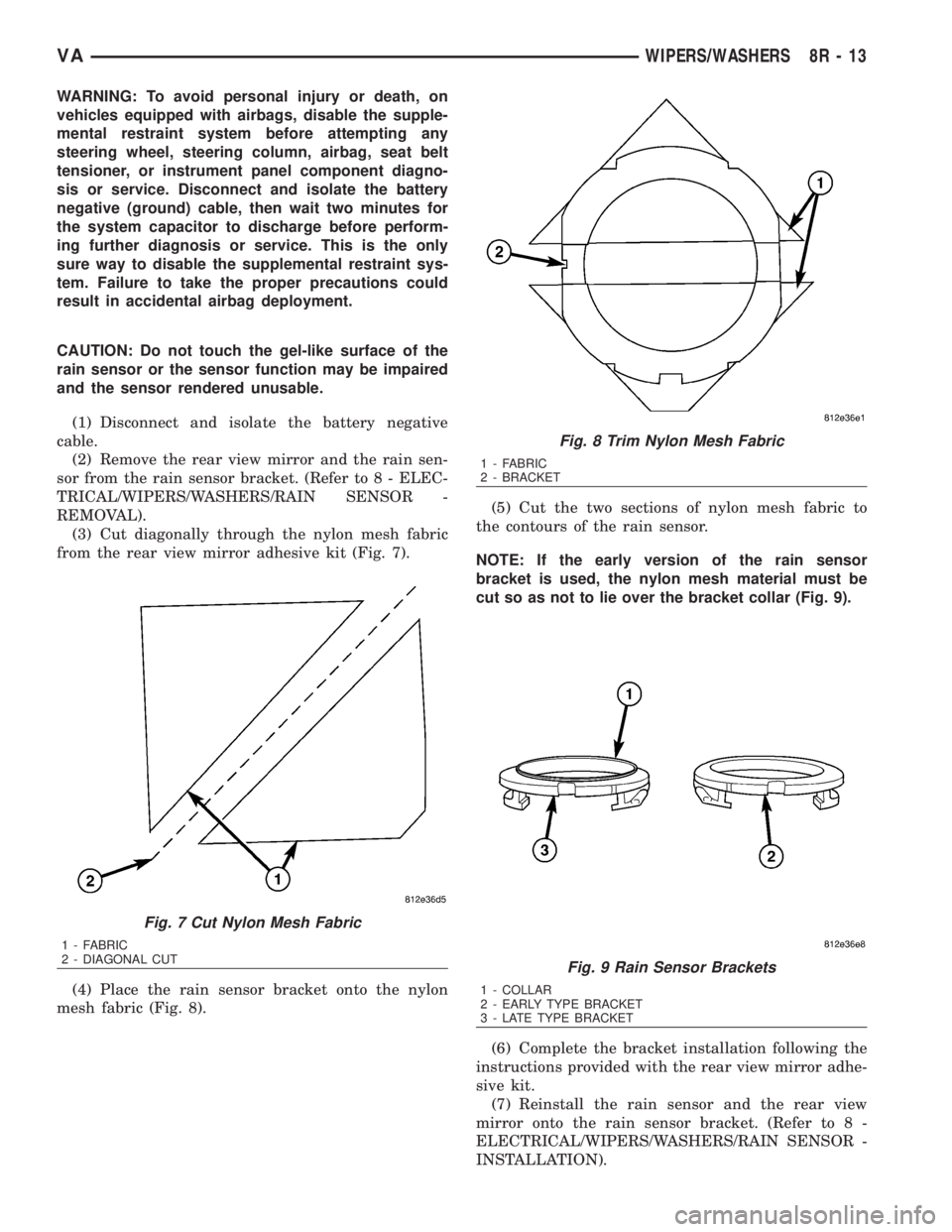
(3) Cut diagonally through the nylon mesh fabric
from the rear view mirror adhesive kit (Fig. 7).
(4) Place the rain sensor bracket onto the nylon
mesh fabric (Fig. 8).(5) Cut the two sections of nylon mesh fabric to
the contours of the rain sensor.
NOTE: If the early version of the rain sensor
bracket is used, the nylon mesh material must be
cut so as not to lie over the bracket collar (Fig. 9).
(6) Complete the bracket installation following the
instructions provided with the rear view mirror adhe-
sive kit.
(7) Reinstall the rain sensor and the rear view
mirror onto the rain sensor bracket. (Refer to 8 -
ELECTRICAL/WIPERS/WASHERS/RAIN SENSOR -
INSTALLATION).
Fig. 7 Cut Nylon Mesh Fabric
1 - FABRIC
2 - DIAGONAL CUT
Fig. 8 Trim Nylon Mesh Fabric
1 - FABRIC
2 - BRACKET
Fig. 9 Rain Sensor Brackets
1 - COLLAR
2 - EARLY TYPE BRACKET
3 - LATE TYPE BRACKET
VAWIPERS/WASHERS 8R - 13