2006 MERCEDES-BENZ SPRINTER transmission oil
[x] Cancel search: transmission oilPage 1618 of 2305
(3) Install the retaining lock for the crankshaft/
ring gear.
NOTE: If the hub of the belt pulley/vibration damper
is tight, use a puller to remove it. Do Not tilt the
puller. The groves of the puller MUST mesh fully
into the slots of the belt pulley.
NOTE: Inspect the running surface of the belt pulley
for wear.
(4) Remove the belt pully/vibration damper.
CAUTION: Care must be taken to prevent severe
damage to the crankshaft and mounting whole for
the front crankshaft seal.
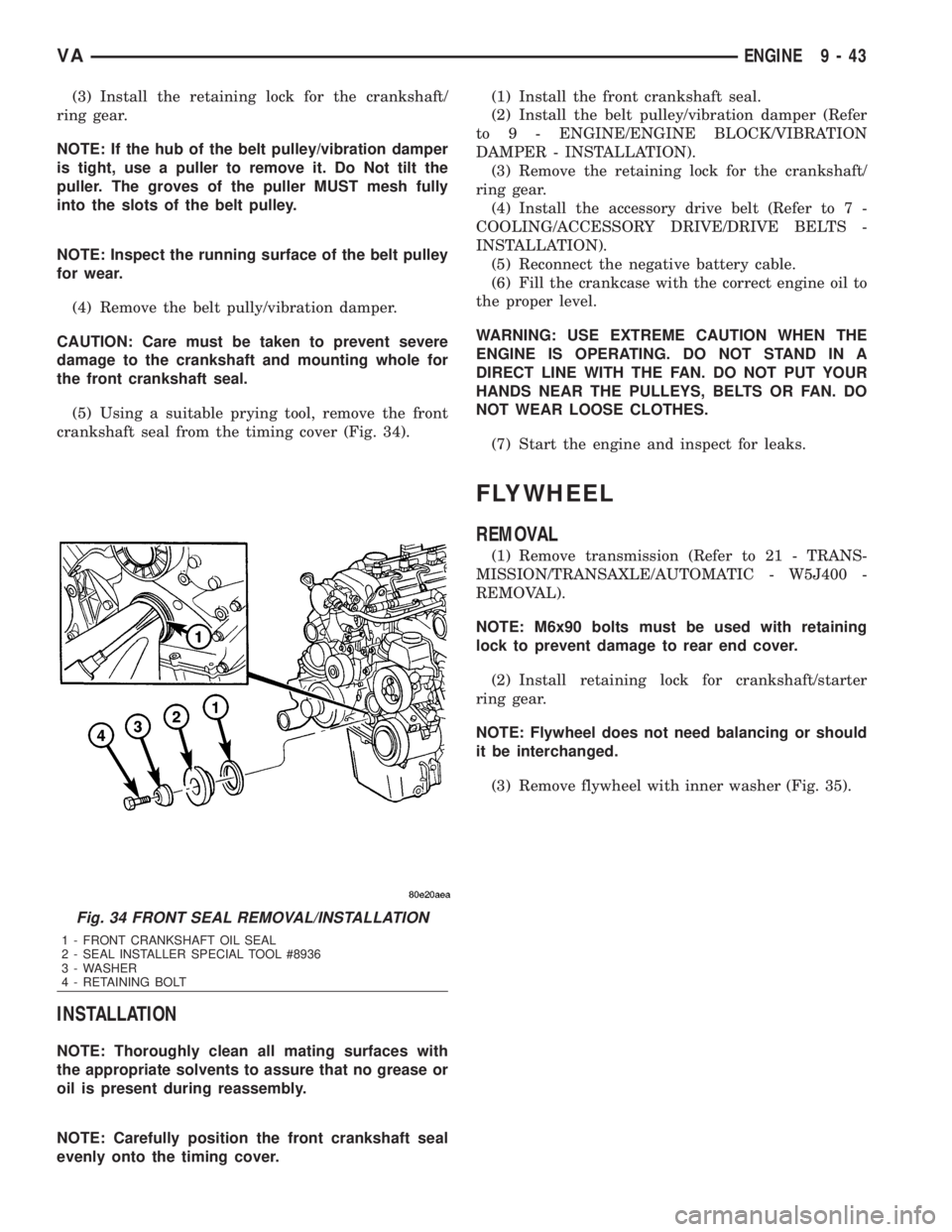
(5) Using a suitable prying tool, remove the front
crankshaft seal from the timing cover (Fig. 34).
INSTALLATION
NOTE: Thoroughly clean all mating surfaces with
the appropriate solvents to assure that no grease or
oil is present during reassembly.
NOTE: Carefully position the front crankshaft seal
evenly onto the timing cover.(1) Install the front crankshaft seal.
(2) Install the belt pulley/vibration damper (Refer
to 9 - ENGINE/ENGINE BLOCK/VIBRATION
DAMPER - INSTALLATION).
(3) Remove the retaining lock for the crankshaft/
ring gear.
(4) Install the accessory drive belt (Refer to 7 -
COOLING/ACCESSORY DRIVE/DRIVE BELTS -
INSTALLATION).
(5) Reconnect the negative battery cable.
(6) Fill the crankcase with the correct engine oil to
the proper level.
WARNING: USE EXTREME CAUTION WHEN THE
ENGINE IS OPERATING. DO NOT STAND IN A
DIRECT LINE WITH THE FAN. DO NOT PUT YOUR
HANDS NEAR THE PULLEYS, BELTS OR FAN. DO
NOT WEAR LOOSE CLOTHES.
(7) Start the engine and inspect for leaks.
FLYWHEEL
REMOVAL
(1) Remove transmission (Refer to 21 - TRANS-
MISSION/TRANSAXLE/AUTOMATIC - W5J400 -
REMOVAL).
NOTE: M6x90 bolts must be used with retaining
lock to prevent damage to rear end cover.
(2) Install retaining lock for crankshaft/starter
ring gear.
NOTE: Flywheel does not need balancing or should
it be interchanged.
(3) Remove flywheel with inner washer (Fig. 35).
Fig. 34 FRONT SEAL REMOVAL/INSTALLATION
1 - FRONT CRANKSHAFT OIL SEAL
2 - SEAL INSTALLER SPECIAL TOOL #8936
3 - WASHER
4 - RETAINING BOLT
VAENGINE 9 - 43
Page 1634 of 2305
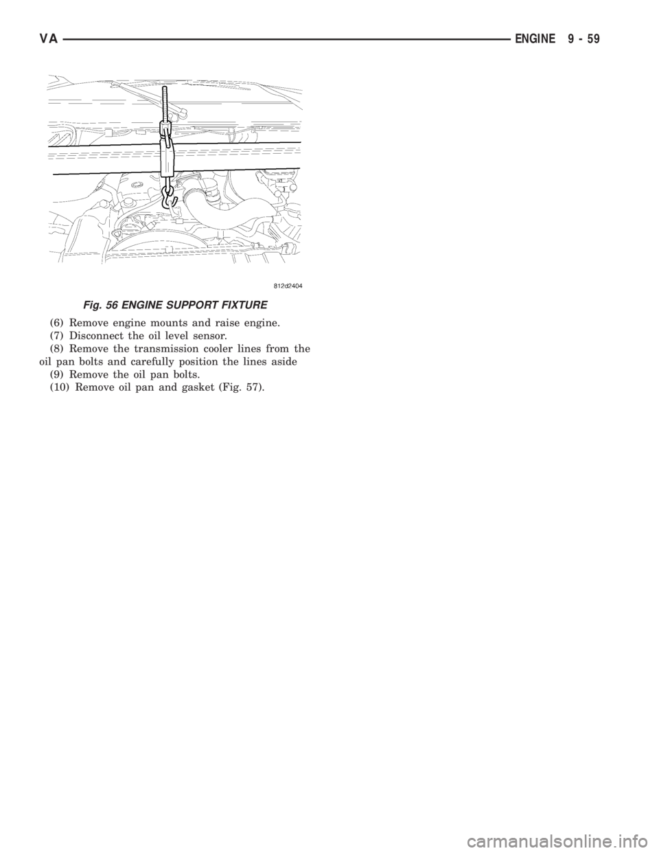
(6) Remove engine mounts and raise engine.
(7) Disconnect the oil level sensor.
(8) Remove the transmission cooler lines from the
oil pan bolts and carefully position the lines aside
(9) Remove the oil pan bolts.
(10) Remove oil pan and gasket (Fig. 57).
Fig. 56 ENGINE SUPPORT FIXTURE
VAENGINE 9 - 59
Page 1635 of 2305
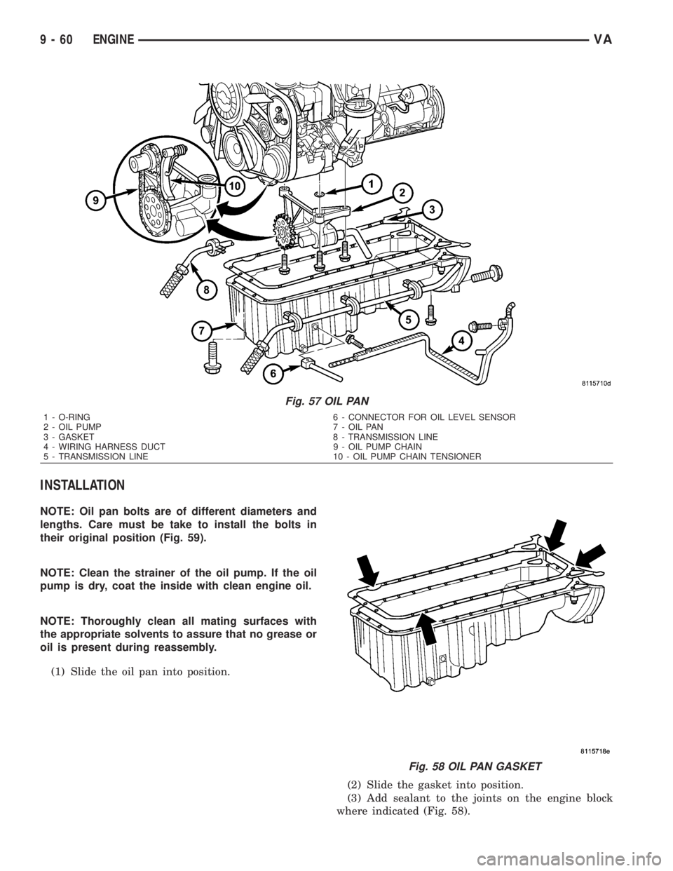
INSTALLATION
NOTE: Oil pan bolts are of different diameters and
lengths. Care must be take to install the bolts in
their original position (Fig. 59).
NOTE: Clean the strainer of the oil pump. If the oil
pump is dry, coat the inside with clean engine oil.
NOTE: Thoroughly clean all mating surfaces with
the appropriate solvents to assure that no grease or
oil is present during reassembly.
(1) Slide the oil pan into position.
(2) Slide the gasket into position.
(3) Add sealant to the joints on the engine block
where indicated (Fig. 58).
Fig. 57 OIL PAN
1 - O-RING 6 - CONNECTOR FOR OIL LEVEL SENSOR
2 - OIL PUMP 7 - OIL PAN
3 - GASKET 8 - TRANSMISSION LINE
4 - WIRING HARNESS DUCT 9 - OIL PUMP CHAIN
5 - TRANSMISSION LINE 10 - OIL PUMP CHAIN TENSIONER
Fig. 58 OIL PAN GASKET
9 - 60 ENGINEVA
Page 1636 of 2305
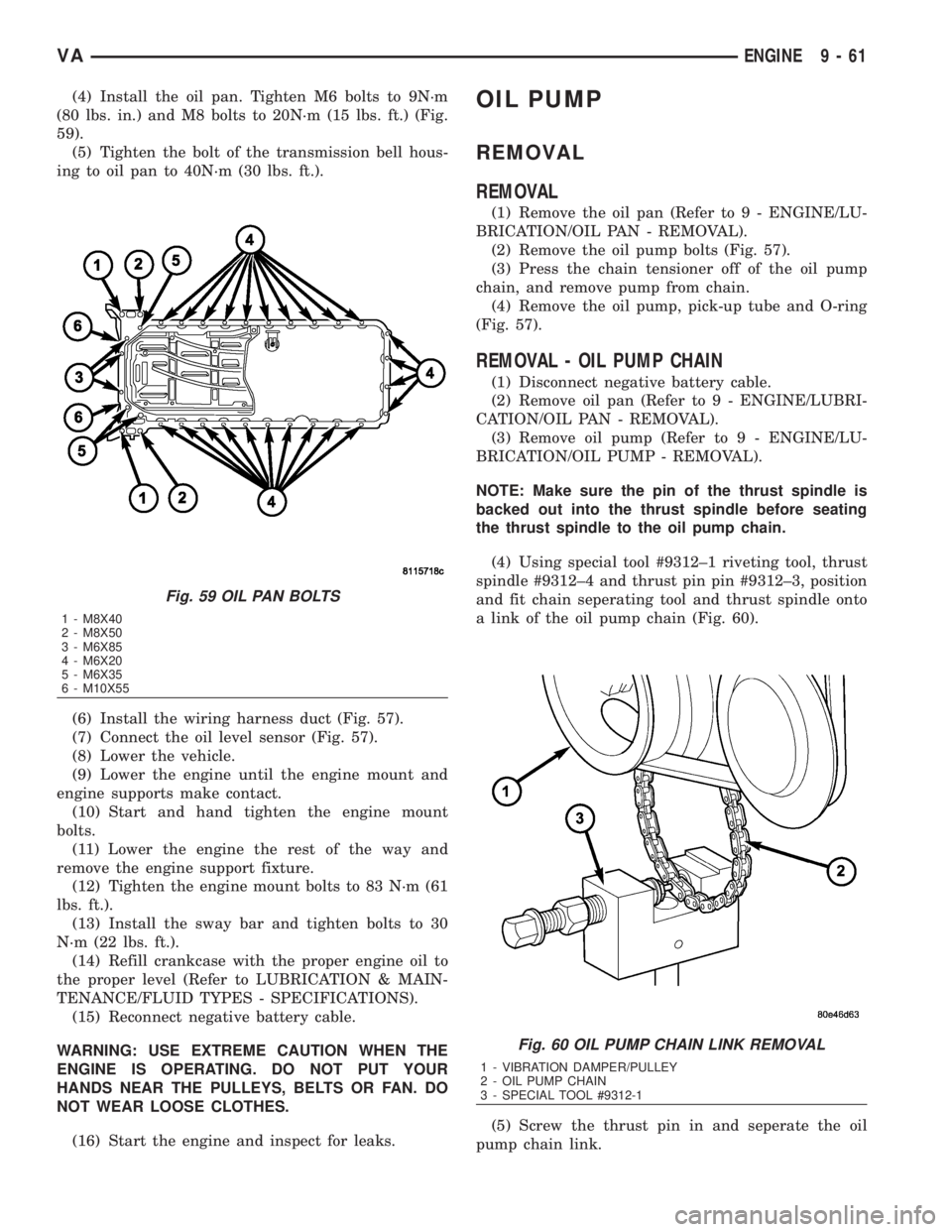
(4) Install the oil pan. Tighten M6 bolts to 9N´m
(80 lbs. in.) and M8 bolts to 20N´m (15 lbs. ft.) (Fig.
59).
(5) Tighten the bolt of the transmission bell hous-
ing to oil pan to 40N´m (30 lbs. ft.).
(6) Install the wiring harness duct (Fig. 57).
(7) Connect the oil level sensor (Fig. 57).
(8) Lower the vehicle.
(9) Lower the engine until the engine mount and
engine supports make contact.
(10) Start and hand tighten the engine mount
bolts.
(11) Lower the engine the rest of the way and
remove the engine support fixture.
(12) Tighten the engine mount bolts to 83 N´m (61
lbs. ft.).
(13) Install the sway bar and tighten bolts to 30
N´m (22 lbs. ft.).
(14) Refill crankcase with the proper engine oil to
the proper level (Refer to LUBRICATION & MAIN-
TENANCE/FLUID TYPES - SPECIFICATIONS).
(15) Reconnect negative battery cable.
WARNING: USE EXTREME CAUTION WHEN THE
ENGINE IS OPERATING. DO NOT PUT YOUR
HANDS NEAR THE PULLEYS, BELTS OR FAN. DO
NOT WEAR LOOSE CLOTHES.
(16) Start the engine and inspect for leaks.OIL PUMP
REMOVAL
REMOVAL
(1) Remove the oil pan (Refer to 9 - ENGINE/LU-
BRICATION/OIL PAN - REMOVAL).
(2) Remove the oil pump bolts (Fig. 57).
(3) Press the chain tensioner off of the oil pump
chain, and remove pump from chain.
(4) Remove the oil pump, pick-up tube and O-ring
(Fig. 57).
REMOVAL - OIL PUMP CHAIN
(1) Disconnect negative battery cable.
(2) Remove oil pan (Refer to 9 - ENGINE/LUBRI-
CATION/OIL PAN - REMOVAL).
(3) Remove oil pump (Refer to 9 - ENGINE/LU-
BRICATION/OIL PUMP - REMOVAL).
NOTE: Make sure the pin of the thrust spindle is
backed out into the thrust spindle before seating
the thrust spindle to the oil pump chain.
(4) Using special tool #9312±1 riveting tool, thrust
spindle #9312±4 and thrust pin pin #9312±3, position
and fit chain seperating tool and thrust spindle onto
a link of the oil pump chain (Fig. 60).
(5) Screw the thrust pin in and seperate the oil
pump chain link.
Fig. 59 OIL PAN BOLTS
1 - M8X40
2 - M8X50
3 - M6X85
4 - M6X20
5 - M6X35
6 - M10X55
Fig. 60 OIL PUMP CHAIN LINK REMOVAL
1 - VIBRATION DAMPER/PULLEY
2 - OIL PUMP CHAIN
3 - SPECIAL TOOL #9312-1
VAENGINE 9 - 61
Page 1730 of 2305
STEERING
TABLE OF CONTENTS
page page
STEERING
DESCRIPTION..........................1
OPERATION............................1
DIAGNOSIS AND TESTING - POWER
STEERING SYSTEM....................1COLUMN................................4
GEAR..................................7
LINKAGE................................9
PUMP..................................11
STEERING
DESCRIPTION
CAUTION: Use approved fluid only in the power
steering system (Refer to LUBRICATION & MAINTE-
NANCE/FLUID TYPES - DESCRIPTION). No other
power steering or automatic transmission fluid is to
be used in the system. Damage may result to the
power steering pump and system if any other fluid
is used, and do not overfill.
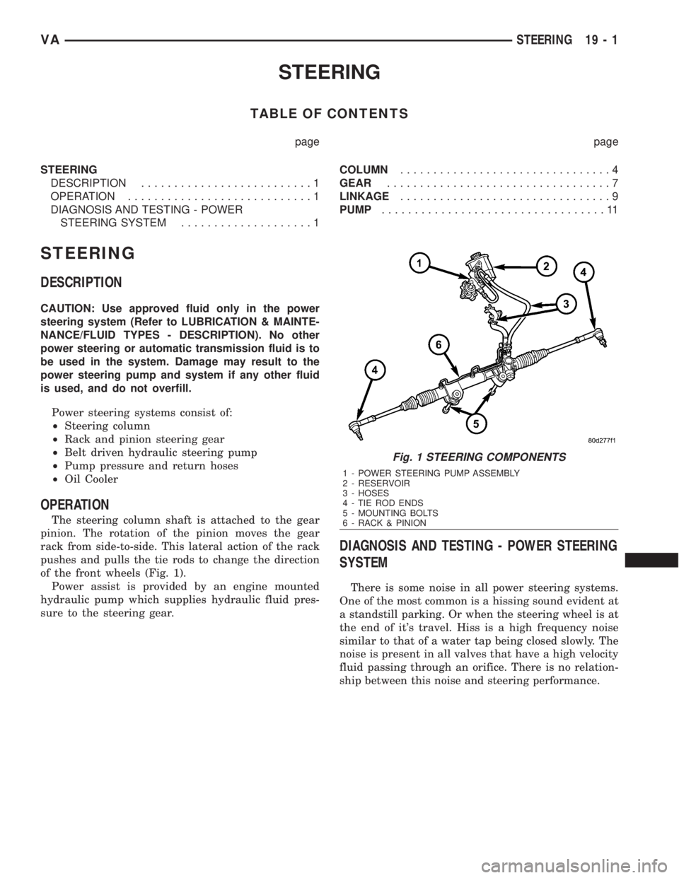
Power steering systems consist of:
²Steering column
²Rack and pinion steering gear
²Belt driven hydraulic steering pump
²Pump pressure and return hoses
²Oil Cooler
OPERATION
The steering column shaft is attached to the gear
pinion. The rotation of the pinion moves the gear
rack from side-to-side. This lateral action of the rack
pushes and pulls the tie rods to change the direction
of the front wheels (Fig. 1).
Power assist is provided by an engine mounted
hydraulic pump which supplies hydraulic fluid pres-
sure to the steering gear.
DIAGNOSIS AND TESTING - POWER STEERING
SYSTEM
There is some noise in all power steering systems.
One of the most common is a hissing sound evident at
a standstill parking. Or when the steering wheel is at
the end of it's travel. Hiss is a high frequency noise
similar to that of a water tap being closed slowly. The
noise is present in all valves that have a high velocity
fluid passing through an orifice. There is no relation-
ship between this noise and steering performance.
Fig. 1 STEERING COMPONENTS
1 - POWER STEERING PUMP ASSEMBLY
2 - RESERVOIR
3 - HOSES
4 - TIE ROD ENDS
5 - MOUNTING BOLTS
6 - RACK & PINION
VASTEERING 19 - 1
Page 1744 of 2305
TRANSMISSION
TABLE OF CONTENTS
page
AUTOMATIC TRANSMISSION NAG1 - SERVICE
INFORMATION............................1
AUTOMATIC TRANSMISSION NAG1 - SERVICE
INFORMATION
TABLE OF CONTENTS
page page
AUTOMATIC TRANSMISSION NAG1 - SERVICE
INFORMATION
DESCRIPTION..........................3
OPERATION............................4
DIAGNOSIS AND TESTING
AUTOMATIC TRANSMISSION............39
PRELIMINARY........................39
ROAD TESTING......................39
AUTOMATIC TRANSMISSION............40
STANDARD PROCEDURE - ALUMINUM
THREAD REPAIR......................42
REMOVAL.............................42
DISASSEMBLY.........................46
ASSEMBLY............................52
INSTALLATION.........................60
SCHEMATICS AND DIAGRAMS............65
SPECIFICATIONS - NAG1 AUTOMATIC
TRANSMISSION......................86
SPECIAL TOOLS - AUTOMATIC
TRANSMISSION - NAG1................87
INPUT CLUTCHES
DESCRIPTION.........................90
OPERATION...........................91
INPUT CLUTCH K1
DISASSEMBLY.........................92
ASSEMBLY............................94
INPUT CLUTCH K2
DISASSEMBLY.........................97
ASSEMBLY............................99
INPUT CLUTCH K3
DISASSEMBLY........................102
ASSEMBLY...........................103
ELECTROHYDRAULIC UNIT
DESCRIPTION........................105
OPERATION..........................112
REMOVAL............................120
DISASSEMBLY........................121
ASSEMBLY...........................125INSTALLATION........................129
FLUID AND FILTER
DESCRIPTION........................131
OPERATION..........................131
DIAGNOSIS AND TESTING
EFFECTS OF INCORRECT FLUID LEVEL . . 131
CAUSES OF BURNT FLUID.............132
FLUID CONTAMINATION...............132
STANDARD PROCEDURE
CHECK OIL LEVEL...................132
TRANSMISSION FILL.................133
FLUID/FILTER SERVICE...............134
FREEWHEELING CLUTCH
DESCRIPTION........................135
OPERATION..........................135
DISASSEMBLY........................136
ASSEMBLY...........................138
GEARSHIFT CABLE
DIAGNOSIS AND TESTING
GEARSHIFT CABLE..................138
REMOVAL............................139
INSTALLATION........................140
HOLDING CLUTCHES
DESCRIPTION........................141
OPERATION..........................142
HOLDING CLUTCH B1
DISASSEMBLY........................143
ASSEMBLY...........................145
HOLDING CLUTCH B2
DISASSEMBLY........................148
ASSEMBLY...........................150
INPUT SPEED SENSORS
DESCRIPTION........................153
OPERATION..........................154
OIL PUMP
DESCRIPTION........................154
OPERATION..........................154
DISASSEMBLY........................155
VATRANSMISSION 21 - 1
Page 1746 of 2305
AUTOMATIC TRANSMISSION NAG1 - SERVICE INFORMATION
DESCRIPTION
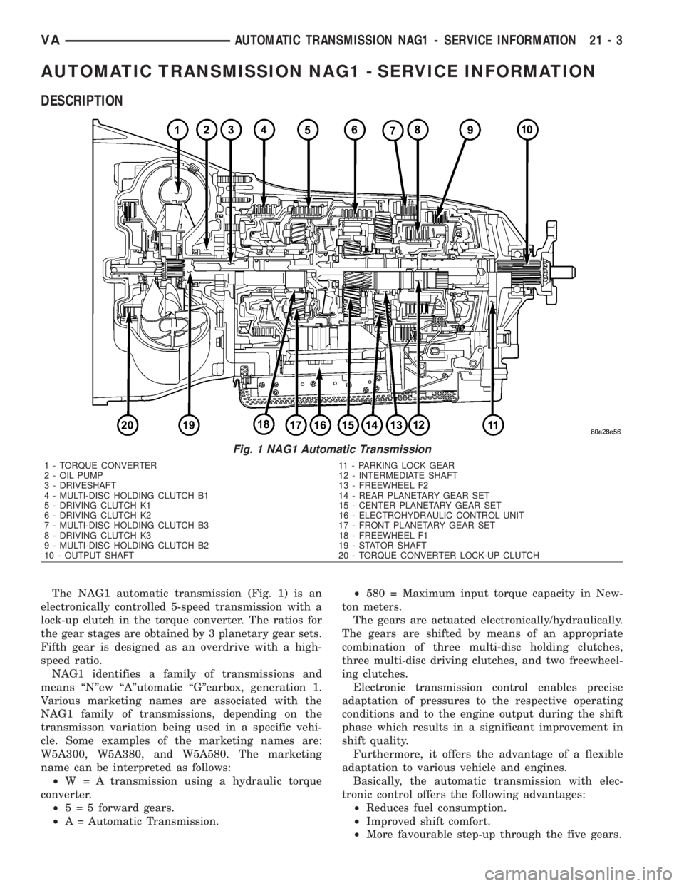
The NAG1 automatic transmission (Fig. 1) is an
electronically controlled 5-speed transmission with a
lock-up clutch in the torque converter. The ratios for
the gear stages are obtained by 3 planetary gear sets.
Fifth gear is designed as an overdrive with a high-
speed ratio.
NAG1 identifies a family of transmissions and
means ªNºew ªAºutomatic ªGºearbox, generation 1.
Various marketing names are associated with the
NAG1 family of transmissions, depending on the
transmisson variation being used in a specific vehi-
cle. Some examples of the marketing names are:
W5A300, W5A380, and W5A580. The marketing
name can be interpreted as follows:
²W = A transmission using a hydraulic torque
converter.
²5 = 5 forward gears.
²A = Automatic Transmission.²580 = Maximum input torque capacity in New-
ton meters.
The gears are actuated electronically/hydraulically.
The gears are shifted by means of an appropriate
combination of three multi-disc holding clutches,
three multi-disc driving clutches, and two freewheel-
ing clutches.
Electronic transmission control enables precise
adaptation of pressures to the respective operating
conditions and to the engine output during the shift
phase which results in a significant improvement in
shift quality.
Furthermore, it offers the advantage of a flexible
adaptation to various vehicle and engines.
Basically, the automatic transmission with elec-
tronic control offers the following advantages:
²Reduces fuel consumption.
²Improved shift comfort.
²More favourable step-up through the five gears.
Fig. 1 NAG1 Automatic Transmission
1 - TORQUE CONVERTER 11 - PARKING LOCK GEAR
2 - OIL PUMP 12 - INTERMEDIATE SHAFT
3 - DRIVESHAFT 13 - FREEWHEEL F2
4 - MULTI-DISC HOLDING CLUTCH B1 14 - REAR PLANETARY GEAR SET
5 - DRIVING CLUTCH K1 15 - CENTER PLANETARY GEAR SET
6 - DRIVING CLUTCH K2 16 - ELECTROHYDRAULIC CONTROL UNIT
7 - MULTI-DISC HOLDING CLUTCH B3 17 - FRONT PLANETARY GEAR SET
8 - DRIVING CLUTCH K3 18 - FREEWHEEL F1
9 - MULTI-DISC HOLDING CLUTCH B2 19 - STATOR SHAFT
10 - OUTPUT SHAFT 20 - TORQUE CONVERTER LOCK-UP CLUTCH
VAAUTOMATIC TRANSMISSION NAG1 - SERVICE INFORMATION 21 - 3
Page 1747 of 2305
²Increased service life and reliability.
²Lower maintenance costs.
TRANSMISSION IDENTIFICATION
The transmission can be generically identified
visually by the presence of a round 13-way connector
located near the front corner of the transmission oil
pan, on the right side. Specific transmission informa-
tion can be found stamped into a pad on the left side
of the transmission, above the oil pan rail.
TRANSMISSION GEAR RATIOS
The gear ratios for the NAG1 automatic transmis-
sion are as follows:
1st Gear............................3.59:1
2nd Gear............................2.19:1
3rd Gear............................1.41:1
4th Gear............................1.00:1
5th Gear............................0.83:1
Reverse.............................3.16:1
TRANSMISSION HOUSING
The converter housing and transmission are made
from a light alloy. These are bolted together and cen-
tered via the outer multi-disc carrier of multi-disc
holding clutch, B1. A coated intermediate plate pro-
vides the sealing. The oil pump and the outer multi-
disc carrier of the multi-disc holding clutch, B1, are
bolted to the converter housing. The stator shaft is
pressed into it and prevented from rotating by
splines. The electrohydraulic unit is bolted to the
transmission housing from underneath. A sheet
metal steel oil pan forms the closure.
MECHANICAL SECTION
The mechanical section consists of a input shaft,
output shaft, a sun gear shaft, and three planetary
gear sets which are coupled to each other. The plan-
etary gear sets each have four planetary pinion
gears. The oil pressure for the torque converter
lock-up clutch and clutch K2 is supplied through
bores in the input shaft. The oil pressure to clutch
K3 is transmitted through the output shaft. The
lubricating oil is distributed through additional bores
in both shafts. All the bearing points of the gear sets,
as well as the freewheeling clutches and actuators,
are supplied with lubricating oil. The parking lock
gear is connected to the output shaft via splines.
Freewheeling clutches F1 and F2 are used to opti-
mize the shifts. The front freewheel, F1, is supported
on the extension of the stator shaft on the transmis-
sion side and, in the locking direction, connects the
sun gear of the front planetary gear set to the trans-
mission housing. In the locking direction, the rear
freewheeling clutch, F2, connects the sun gear of the
center planetary gear set to the sun gear of the rear
planetary gear set.
ELECTROHYDRAULIC CONTROL UNIT
The electrohydraulic control unit comprises the
shift plate made from light alloy for the hydraulic
control and an electrical control unit. The electrical
control unit comprises of a supporting body made of
plastic, into which the electrical components are
assembled. The supporting body is mounted on the
shift plate and screwed to it.
Strip conductors inserted into the supporting body
make the connection between the electrical compo-
nents and a plug connector. The connection to the
wiring harness on the vehicle and the transmission
control module (TCM) is produced via this 13-pin
plug connector with a bayonet lock.
SHIFT GROUPS
The hydraulic control components (including actua-
tors) which are responsible for the pressure distribu-
tion before, during, and after a gear change are
described as a shift group. Each shift group contains
a command valve, a holding pressure shift valve, a
shift pressure shift valve, overlap regulating valve,
and a solenoid.
The hydraulic system contains three shift groups:
1-2/4-5, 2-3, and 3-4. Each shift group can also be
described as being in one of two possible states. The
active shift group is described as being in the shift
phase when it is actively engaging/disengaging a
clutch combination. The 1-2/4-5 shift group control
the B1 and K1 clutches. The 2-3 shift group controls
the K2 and K3 clutches. The 3-4 shift group controls
the K3 and B2 clutches.
OPERATION
The transmission control is divided into the elec-
tronic and hydraulic transmission control functions.
While the electronic transmission control is responsi-
ble for gear selection and for matching the pressures
to the torque to be transmitted, the transmission's
power supply control occurs via hydraulic elements
in the electrohydraulic control module. The oil supply
to the hydraulic elements, such as the hydrodynamic
torque converter, the shift elements and the hydrau-
lic transmission control, is provided by way of an oil
pump connected with the torque converter.
The Transmission Control Module (TCM) allows for
the precise adaptation of pressures to the correspond-
ing operating conditions and to the engine output
during the gearshift phase, resulting in a noticeable
improvement in shift quality. The engine speed limit
can be reached in the individual gears at full throttle
and kickdown. The shift range can be changed in the
forward gears while driving, but the TCM employs a
downshift safeguard to prevent over-revving the
engine. The system offers the additional advantage of
21 - 4 AUTOMATIC TRANSMISSION NAG1 - SERVICE INFORMATIONVA