2006 MERCEDES-BENZ SPRINTER transmission oil
[x] Cancel search: transmission oilPage 1582 of 2305
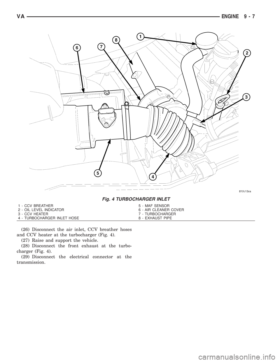
(26) Disconnect the air inlet, CCV breather hoses
and CCV heater at the turbocharger (Fig. 4).
(27) Raise and support the vehicle.
(28) Disconnect the front exhaust at the turbo-
charger (Fig. 4).
(29) Disconnect the electrical connector at the
transmission.
Fig. 4 TURBOCHARGER INLET
1 - CCV BREATHER 5 - MAF SENSOR
2 - OIL LEVEL INDICATOR 6 - AIR CLEANER COVER
3 - CCV HEATER 7 - TURBOCHARGER
4 - TURBOCHARGER INLET HOSE 8 - EXHAUST PIPE
VAENGINE 9 - 7
Page 1583 of 2305
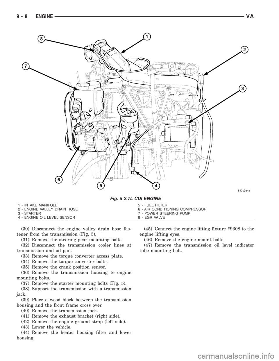
(30) Disconnect the engine valley drain hose fas-
tener from the transmission (Fig. 5).
(31) Remove the steering gear mounting bolts.
(32) Disconnect the transmission cooler lines at
transmission and oil pan.
(33) Remove the torque converter access plate.
(34) Remove the torque converter bolts.
(35) Remove the crank position sensor.
(36) Remove the transmission housing to engine
mounting bolts.
(37) Remove the starter mounting bolts (Fig. 5).
(38) Support the transmission with a transmission
jack.
(39) Place a wood block between the transmission
housing and the front frame cross over.
(40) Remove the transmission jack.
(41) Remove the exhaust bracket (right side).
(42) Remove the engine ground strap (left side).
(43) Lower the vehicle.
(44) Remove the heater housing filter and lower
housing.(45) Connect the engine lifting fixture #9308 to the
engine lifting eyes.
(46) Remove the engine mount bolts.
(47) Remove the transmission oil level indicator
tube mounting bolt.
Fig. 5 2.7L CDI ENGINE
1 - INTAKE MANIFOLD 5 - FUEL FILTER
2 - ENGINE VALLEY DRAIN HOSE 6 - AIR CONDITIONING COMPRESSOR
3 - STARTER 7 - POWER STEERING PUMP
4 - ENGINE OIL LEVEL SENSOR 8 - EGR VALVE
9 - 8 ENGINEVA
Page 1585 of 2305
(11) Install the torque converter access plate. Refer
to (Refer to 21 - TRANSMISSION/TRANSAXLE/AU-
TOMATIC - NAG1 - INSTALLATION) for correct
sequence and torque specification.
(12) Install the transmission cooler lines to trans-
mission. (Refer to 21 - TRANSMISSION/TRANS-
AXLE/AUTOMATIC - NAG1 - INSTALLATION) for
correct sequence and torque specification.
(13) Connect the engine valley drain hose to the
transmission (Fig. 5).
(14) Install transmission electrical connector and
shifter hardware. Refer to (Refer to 21 - TRANSMIS-
SION/TRANSAXLE/AUTOMATIC - NAG1 - INSTAL-
LATION) for correct sequence and torque
specification.
(15) Install the steering gear and tighten in two
stages. 25 N´m (18.5 lbs. ft.), then 45 N´m (33 lbs. ft.)
plus 90É.
(16) Install the starter.
(17) Connect the ground strap (left side).
(18) Align and install the exhaust and bracket
(Refer to 11 - EXHAUST SYSTEM/EXHAUST PIPE -
INSTALLATION).
(19) Lower the vehicle.
(20) Install the lower heater housing and filter.
(21) Install the air inlet hose, CCV breather and
CCV heater at the turbocharger (Fig. 4).
(22) Connect the coolant supply and return hoses.
(23) Connect the brake booster vacuum hose at the
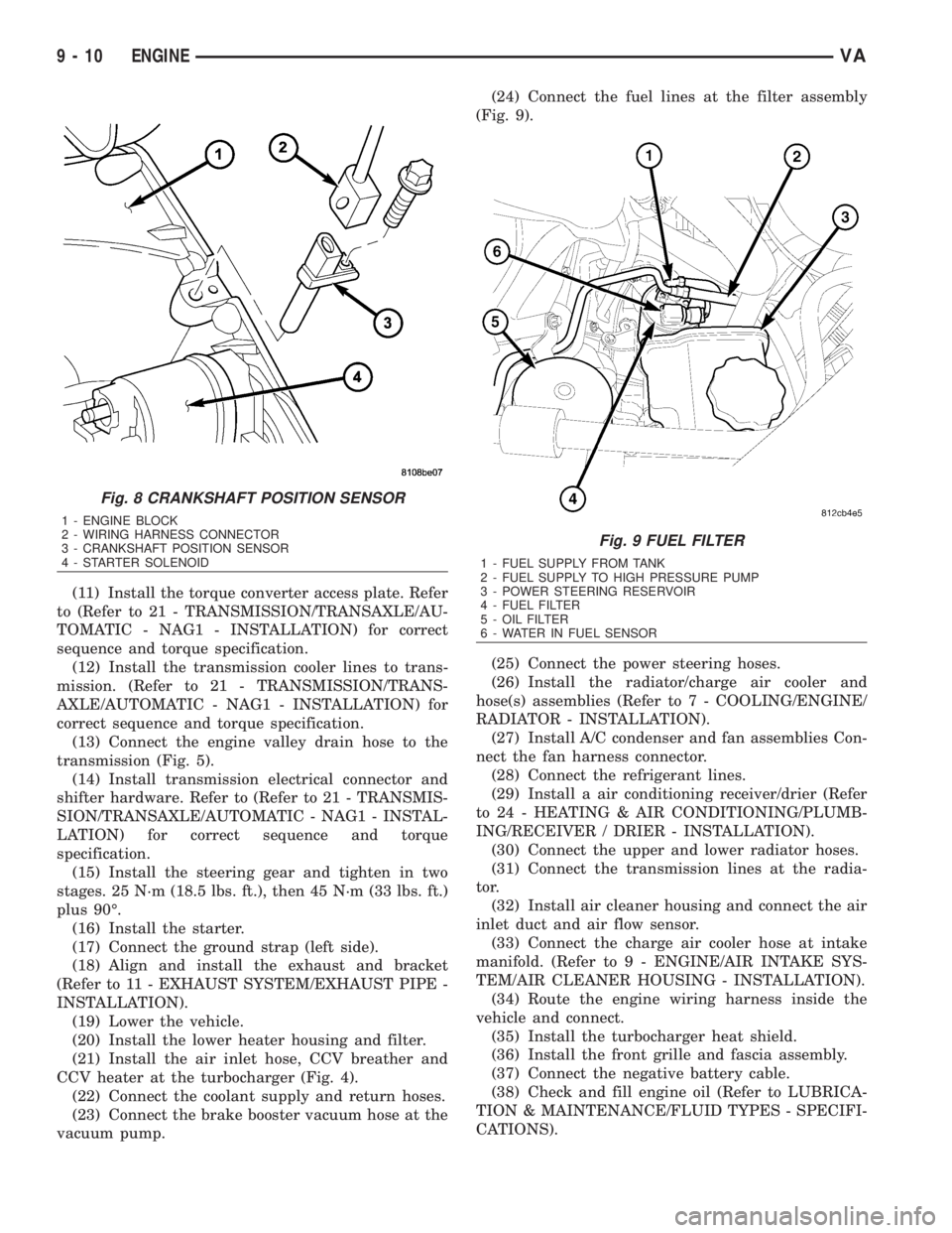
vacuum pump.(24) Connect the fuel lines at the filter assembly
(Fig. 9).
(25) Connect the power steering hoses.
(26) Install the radiator/charge air cooler and
hose(s) assemblies (Refer to 7 - COOLING/ENGINE/
RADIATOR - INSTALLATION).
(27) Install A/C condenser and fan assemblies Con-
nect the fan harness connector.
(28) Connect the refrigerant lines.
(29) Install a air conditioning receiver/drier (Refer
to 24 - HEATING & AIR CONDITIONING/PLUMB-
ING/RECEIVER / DRIER - INSTALLATION).
(30) Connect the upper and lower radiator hoses.
(31) Connect the transmission lines at the radia-
tor.
(32) Install air cleaner housing and connect the air
inlet duct and air flow sensor.
(33) Connect the charge air cooler hose at intake
manifold. (Refer to 9 - ENGINE/AIR INTAKE SYS-
TEM/AIR CLEANER HOUSING - INSTALLATION).
(34) Route the engine wiring harness inside the
vehicle and connect.
(35) Install the turbocharger heat shield.
(36) Install the front grille and fascia assembly.
(37) Connect the negative battery cable.
(38) Check and fill engine oil (Refer to LUBRICA-
TION & MAINTENANCE/FLUID TYPES - SPECIFI-
CATIONS).
Fig. 8 CRANKSHAFT POSITION SENSOR
1 - ENGINE BLOCK
2 - WIRING HARNESS CONNECTOR
3 - CRANKSHAFT POSITION SENSOR
4 - STARTER SOLENOID
Fig. 9 FUEL FILTER
1 - FUEL SUPPLY FROM TANK
2 - FUEL SUPPLY TO HIGH PRESSURE PUMP
3 - POWER STEERING RESERVOIR
4 - FUEL FILTER
5 - OIL FILTER
6 - WATER IN FUEL SENSOR
9 - 10 ENGINEVA
Page 1589 of 2305
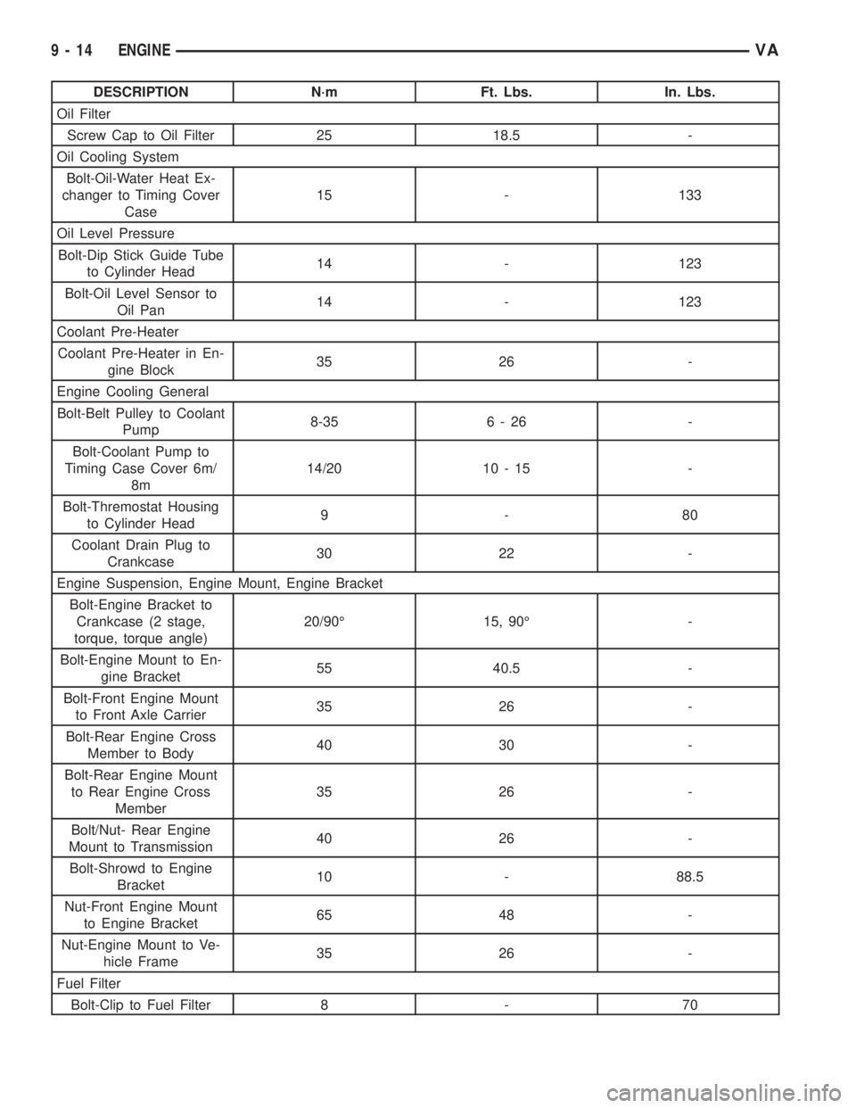
DESCRIPTION N´m Ft. Lbs. In. Lbs.
Oil Filter
Screw Cap to Oil Filter 25 18.5 -
Oil Cooling System
Bolt-Oil-Water Heat Ex-
changer to Timing Cover
Case15 - 133
Oil Level Pressure
Bolt-Dip Stick Guide Tube
to Cylinder Head14 - 123
Bolt-Oil Level Sensor to
Oil Pan14 - 123
Coolant Pre-Heater
Coolant Pre-Heater in En-
gine Block35 26 -
Engine Cooling General
Bolt-Belt Pulley to Coolant
Pump8-35 6 - 26 -
Bolt-Coolant Pump to
Timing Case Cover 6m/
8m14/20 10 - 15 -
Bolt-Thremostat Housing
to Cylinder Head9-80
Coolant Drain Plug to
Crankcase30 22 -
Engine Suspension, Engine Mount, Engine Bracket
Bolt-Engine Bracket to
Crankcase (2 stage,
torque, torque angle)20/90É 15, 90É -
Bolt-Engine Mount to En-
gine Bracket55 40.5 -
Bolt-Front Engine Mount
to Front Axle Carrier35 26 -
Bolt-Rear Engine Cross
Member to Body40 30 -
Bolt-Rear Engine Mount
to Rear Engine Cross
Member35 26 -
Bolt/Nut- Rear Engine
Mount to Transmission40 26 -
Bolt-Shrowd to Engine
Bracket10 - 88.5
Nut-Front Engine Mount
to Engine Bracket65 48 -
Nut-Engine Mount to Ve-
hicle Frame35 26 -
Fuel Filter
Bolt-Clip to Fuel Filter 8 - 70
9 - 14 ENGINEVA
Page 1590 of 2305
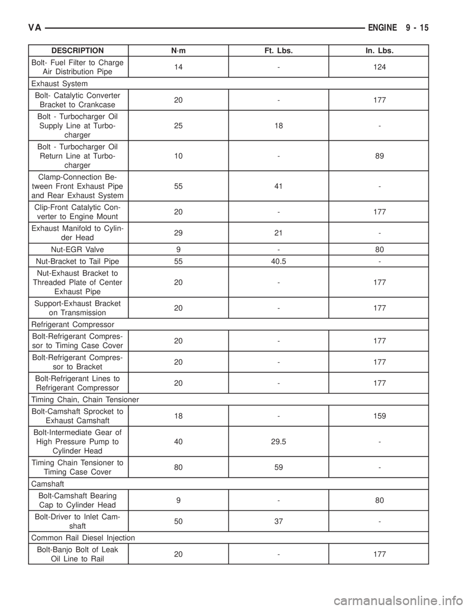
DESCRIPTION N´m Ft. Lbs. In. Lbs.
Bolt- Fuel Filter to Charge
Air Distribution Pipe14 - 124
Exhaust System
Bolt- Catalytic Converter
Bracket to Crankcase20 - 177
Bolt - Turbocharger Oil
Supply Line at Turbo-
charger25 18 -
Bolt - Turbocharger Oil
Return Line at Turbo-
charger10 - 89
Clamp-Connection Be-
tween Front Exhaust Pipe
and Rear Exhaust System55 41 -
Clip-Front Catalytic Con-
verter to Engine Mount20 - 177
Exhaust Manifold to Cylin-
der Head29 21 -
Nut-EGR Valve 9 - 80
Nut-Bracket to Tail Pipe 55 40.5 -
Nut-Exhaust Bracket to
Threaded Plate of Center
Exhaust Pipe20 - 177
Support-Exhaust Bracket
on Transmission20 - 177
Refrigerant Compressor
Bolt-Refrigerant Compres-
sor to Timing Case Cover20 - 177
Bolt-Refrigerant Compres-
sor to Bracket20 - 177
Bolt-Refrigerant Lines to
Refrigerant Compressor20 - 177
Timing Chain, Chain Tensioner
Bolt-Camshaft Sprocket to
Exhaust Camshaft18 - 159
Bolt-Intermediate Gear of
High Pressure Pump to
Cylinder Head40 29.5 -
Timing Chain Tensioner to
Timing Case Cover80 59 -
Camshaft
Bolt-Camshaft Bearing
Cap to Cylinder Head9-80
Bolt-Driver to Inlet Cam-
shaft50 37 -
Common Rail Diesel Injection
Bolt-Banjo Bolt of Leak
Oil Line to Rail20 - 177
VAENGINE 9 - 15
Page 1599 of 2305
(12) Remove the camshaft housing at the cylinder
head (Fig. 14).
(13) Remove the high pressure pump.
(14) Remove the front head cover plate.
WARNING: NO FIRE, OPEN FLAMES OR SMOKING.
RISK OF POISONING FROM INHALING AND SWAL-
LOWING FUEL. RISK OF INJURY FROM SKIN AND
EYE CONTACT WITH FUEL. POUR FUELS ONLY
INTO SUITABLE AND APPROPRIATELY MARKED
CONTAINERS. WEAR PROTECTIVE CLOTHING
WHEN HANDLING FUEL.
(15) Remove the high pressure fuel pump interme-
diate gear (Fig. 14).
(16) Disconnect the engine side of the engine har-
ness and set aside.
(17) Disconnect the charge air pipe at the cylinder
head and set aside with the engine harness con-
nected.
(18) Remove the turbocharger oil supply line at
the cylinder head and turbocharger (Fig. 14).
(19) Disconnect the turbocharger at the exhaust
manifold (Fig. 14).(20) Unbolt the transmission oil level indicator
tube fasteners from the cylinder head and engine
block (Fig. 14).
(21) Disconnect the upper radiator hose and by
pass hose at the thermostat housing (Fig. 14).
NOTE: Capture any fuel spillage when disconnect-
ing fuel lines.
(22) Disconnect the fuel line at the rear of the fuel
rail (Fig. 14).
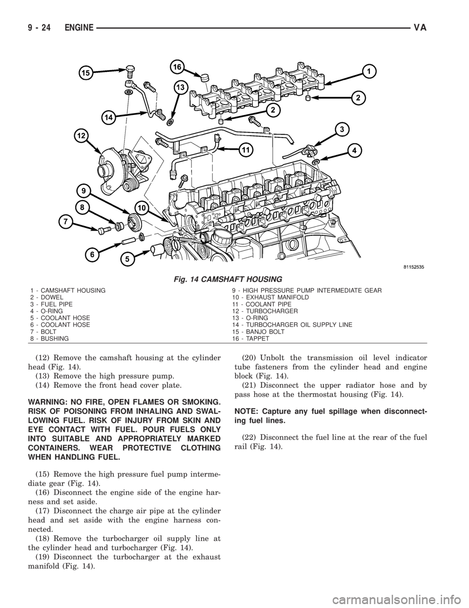
Fig. 14 CAMSHAFT HOUSING
1 - CAMSHAFT HOUSING 9 - HIGH PRESSURE PUMP INTERMEDIATE GEAR
2 - DOWEL 10 - EXHAUST MANIFOLD
3 - FUEL PIPE 11 - COOLANT PIPE
4 - O-RING 12 - TURBOCHARGER
5 - COOLANT HOSE 13 - O-RING
6 - COOLANT HOSE 14 - TURBOCHARGER OIL SUPPLY LINE
7 - BOLT 15 - BANJO BOLT
8 - BUSHING 16 - TAPPET
9 - 24 ENGINEVA
Page 1602 of 2305
(2) Hand start clean head bolts and tighten per
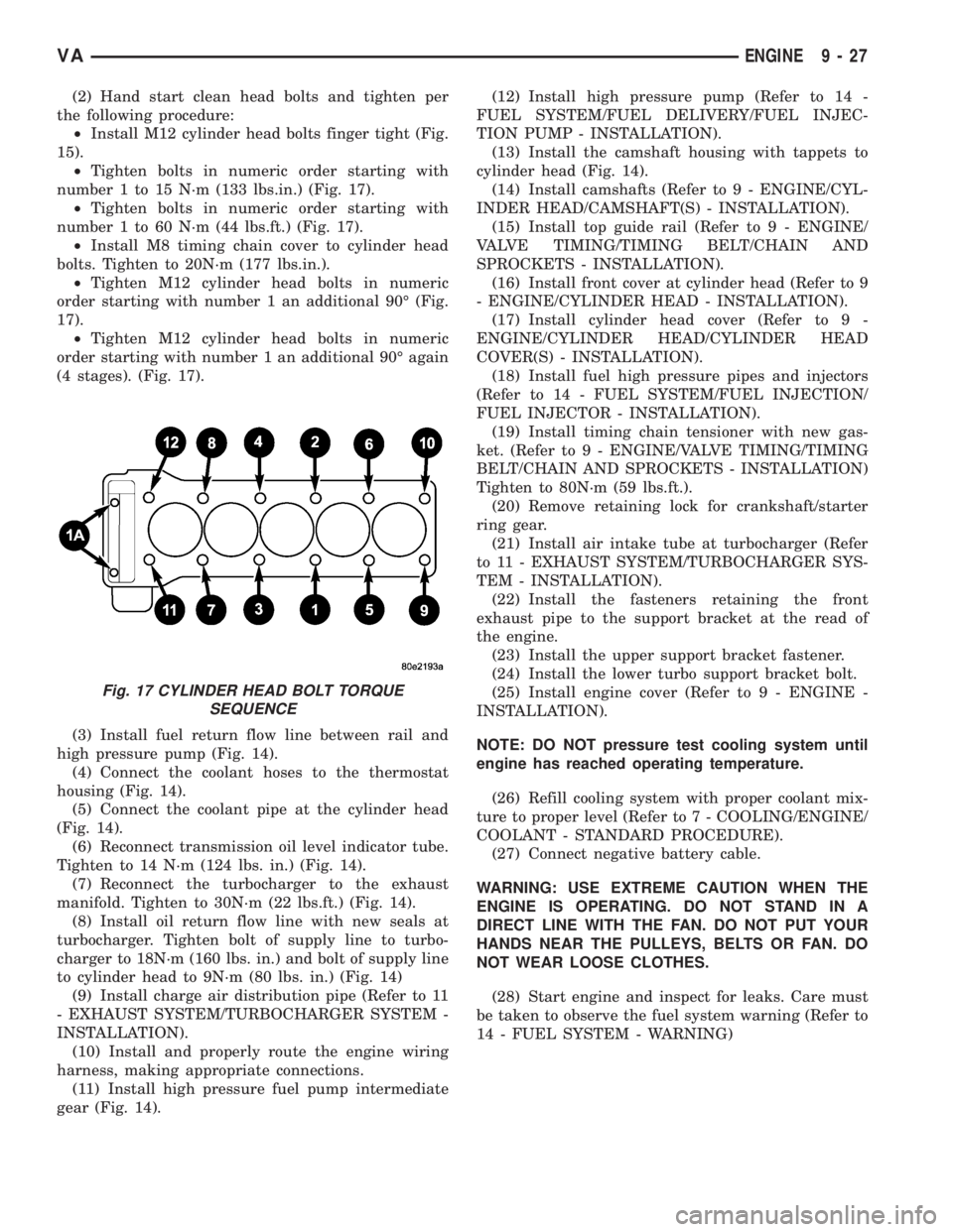
the following procedure:
²Install M12 cylinder head bolts finger tight (Fig.
15).
²Tighten bolts in numeric order starting with
number 1 to 15 N´m (133 lbs.in.) (Fig. 17).
²Tighten bolts in numeric order starting with
number 1 to 60 N´m (44 lbs.ft.) (Fig. 17).
²Install M8 timing chain cover to cylinder head
bolts. Tighten to 20N´m (177 lbs.in.).
²Tighten M12 cylinder head bolts in numeric
order starting with number 1 an additional 90É (Fig.
17).
²Tighten M12 cylinder head bolts in numeric
order starting with number 1 an additional 90É again
(4 stages). (Fig. 17).
(3) Install fuel return flow line between rail and
high pressure pump (Fig. 14).
(4) Connect the coolant hoses to the thermostat
housing (Fig. 14).
(5) Connect the coolant pipe at the cylinder head
(Fig. 14).
(6) Reconnect transmission oil level indicator tube.
Tighten to 14 N´m (124 lbs. in.) (Fig. 14).
(7) Reconnect the turbocharger to the exhaust
manifold. Tighten to 30N´m (22 lbs.ft.) (Fig. 14).
(8) Install oil return flow line with new seals at
turbocharger. Tighten bolt of supply line to turbo-
charger to 18N´m (160 lbs. in.) and bolt of supply line
to cylinder head to 9N´m (80 lbs. in.) (Fig. 14)
(9) Install charge air distribution pipe (Refer to 11
- EXHAUST SYSTEM/TURBOCHARGER SYSTEM -
INSTALLATION).
(10) Install and properly route the engine wiring
harness, making appropriate connections.
(11) Install high pressure fuel pump intermediate
gear (Fig. 14).(12) Install high pressure pump (Refer to 14 -
FUEL SYSTEM/FUEL DELIVERY/FUEL INJEC-
TION PUMP - INSTALLATION).
(13) Install the camshaft housing with tappets to
cylinder head (Fig. 14).
(14) Install camshafts (Refer to 9 - ENGINE/CYL-
INDER HEAD/CAMSHAFT(S) - INSTALLATION).
(15) Install top guide rail (Refer to 9 - ENGINE/
VALVE TIMING/TIMING BELT/CHAIN AND
SPROCKETS - INSTALLATION).
(16) Install front cover at cylinder head (Refer to 9
- ENGINE/CYLINDER HEAD - INSTALLATION).
(17) Install cylinder head cover (Refer to 9 -
ENGINE/CYLINDER HEAD/CYLINDER HEAD
COVER(S) - INSTALLATION).
(18) Install fuel high pressure pipes and injectors
(Refer to 14 - FUEL SYSTEM/FUEL INJECTION/
FUEL INJECTOR - INSTALLATION).
(19) Install timing chain tensioner with new gas-
ket. (Refer to 9 - ENGINE/VALVE TIMING/TIMING
BELT/CHAIN AND SPROCKETS - INSTALLATION)
Tighten to 80N´m (59 lbs.ft.).
(20) Remove retaining lock for crankshaft/starter
ring gear.
(21) Install air intake tube at turbocharger (Refer
to 11 - EXHAUST SYSTEM/TURBOCHARGER SYS-
TEM - INSTALLATION).
(22) Install the fasteners retaining the front
exhaust pipe to the support bracket at the read of
the engine.
(23) Install the upper support bracket fastener.
(24) Install the lower turbo support bracket bolt.
(25) Install engine cover (Refer to 9 - ENGINE -
INSTALLATION).
NOTE: DO NOT pressure test cooling system until
engine has reached operating temperature.
(26) Refill cooling system with proper coolant mix-
ture to proper level (Refer to 7 - COOLING/ENGINE/
COOLANT - STANDARD PROCEDURE).
(27) Connect negative battery cable.
WARNING: USE EXTREME CAUTION WHEN THE
ENGINE IS OPERATING. DO NOT STAND IN A
DIRECT LINE WITH THE FAN. DO NOT PUT YOUR
HANDS NEAR THE PULLEYS, BELTS OR FAN. DO
NOT WEAR LOOSE CLOTHES.
(28) Start engine and inspect for leaks. Care must
be taken to observe the fuel system warning (Refer to
14 - FUEL SYSTEM - WARNING)
Fig. 17 CYLINDER HEAD BOLT TORQUE
SEQUENCE
VAENGINE 9 - 27
Page 1616 of 2305
CAUTION: Oil thread and head contact surfaces of
bolts that retain the crankshaft bearing caps;
tighten bolts from inside to outside, beginning at
the fit bearing. Rotate crankshaft to check clear-
ance.
(1) Install crankshaft.
CAUTION: The crankshaft bearing caps are num-
bered consecutively, beginning with the first crank-
shaft bearing cap at the front of the engine.
Attention must be paid to the way the crankshaft
bearing caps fit. If correctly installed, the lug, or
raised boss, on the crankshaft bearing cap is point-
ing to the left when viewed in the direction of travel
(intake side).
(2) Install the crankshaft bearing caps. Tighten
bolts in two stages. 55N´m (40.5 lbs. ft.), then 90É.
(3) Install the pistons (Refer to 9 - ENGINE/EN-
GINE BLOCK/PISTON & CONNECTING ROD -
INSTALLATION).
(4) Install the end cover (Refer to 9 - ENGINE/EN-
GINE BLOCK/CRANKSHAFT OIL SEAL - REAR -
INSTALLATION).
(5) Install the timing case cover (Refer to 9 -
ENGINE/VALVE TIMING/TIMING BELT / CHAIN
COVER(S) - INSTALLATION).
(6) Install the engine (Refer to 9 - ENGINE -
INSTALLATION).
(7) Fill the crankcase with the correct engine oil,
to the proper level. Refer to the owners manual for
specifications.
(8) Fill the cooling system with the proper coolant,
to the proper level (Refer to 7 - COOLING/ENGINE/
COOLANT - STANDARD PROCEDURE).
(9) Connect the negative battery cable.
WARNING: USE EXTREME CAUTION WHEN THE
ENGINE IS OPERATING. DO NOT STAND IN A
DIRECT LINE WITH THE FAN. DO NOT PUT YOUR
HANDS NEAR THE PULLEYS, BELTS, OR FAN. DO
NOT WEAR LOOSE CLOTHES.
(10) Start engine and inspect for leaks. Care must
be taken to observe the fuel system warning (Refer to
14 - FUEL SYSTEM - WARNING).
CRANKSHAFT OIL SEAL -
REAR
REMOVAL
This must be done with the transmission removed
from the vehicle.
(1) Disconnect the negative battery cable.
(2) Raise and support the vehicle.
(3) Drain the engine oil.NOTE: Loosen all of the oil pan bolts to assure that
the oil pan gasket is not damaged when removing
the rear main oil seal and end cover assembly.
NOTE: Inspect the oil pan gasket for damage. If the
oil pan gasket is damaged, remove the oil pan and
replace the oil pan gasket.
(4) Loosen the oil pan bolts.
(5) Remove the flywheel.
CAUTION: Care must be taken when removing the
rear main seal and adaptor assembly. Failure to do
so will result in damage to the oil pan gasket.
(6) Remove the rear main seal/adaptor retaining
bolts and carefully pry the adaptor from the crank-
case at the adaptor shoulders (Fig. 33).
VAENGINE 9 - 41