2006 MERCEDES-BENZ SPRINTER transmission oil
[x] Cancel search: transmission oilPage 846 of 2305

(17) Take off charge air cooler together with cool-
ing loop of the steering at the radiator (Fig. 10).
(18) Remove bottom radiator trim (Fig. 10).
(19) Detach coolant hose at radiator.
(20) Detach coolant pipe together with coolant
hose at the fan shroud.
(21) Remove radiator fan shroud (Fig. 10).
INSTALLATION
(1) Install fan shroud to radiator (Fig. 10).
(2) Attach coolant pipe with hoses to fan shroud
(Fig. 10).
(3) Attach coolant hose at radiator (Fig. 10).
(4) Install bottom radiator trim (Fig. 10).
(5) Install charge air cooler along with cooling loop
of the power steering, to radiator (Fig. 10).
(6) Install radiator assembly into the rubber grom-
mets (Fig. 9).
(7) Install both right and left side radiator trim
panels (Fig. 9).
(8) Attach the transmission cooler lines (Fig. 9).
(9) Attach coolant hose to the bottom right of the
radiator (Fig. 9).
(10) Attach both power steering hydraulic lines
(Fig. 9).
(11) Connect coolant level sensor electrical connec-
tor (Fig. 9).
(12) Connect coolant hoses to the coolant reservoir,
radiator and water pump (Fig. 9).(13) Attach air intake pipe at the body.
(14) Attach charge air hose at air intake.
(15) Attach charge air hose at turbocharger.
(16) Install A/C condenser.
(17) Install front bumper.
(18) Install front end cross member.
(19) Refill power steering to proper level.
(20) Refill transmission to proper level.
(21) Close radiator drain plug and refill the cooling
system (Refer to 7 - COOLING/ENGINE/COOLANT -
STANDARD PROCEDURE).
(22) Recharge air conditioning (Refer to 24 -
HEATING & AIR CONDITIONING/PLUMBING -
STANDARD PROCEDURE).
(23) Run engine until warm and check for leaks.
RADIATOR PRESSURE CAP
DESCRIPTION
All vehicles are equipped with a pressure cap (Fig.
11). This cap releases pressure at some point within
a range of 124-145 kPa (18-21 psi). The pressure
relief point (in pounds) is engraved on top of the cap
The cooling system will operate at pressures
slightly above atmospheric pressure. This results in a
higher coolant boiling point allowing increased radi-
ator cooling capacity. The cap contains a spring-
loaded pressure relief valve. This valve opens when
system pressure reaches the release range of 124-145
kPa (18-21 psi).
A rubber gasket seals the radiator filler neck. This
is done to maintain vacuum during coolant cool-down
and to prevent leakage when system is under pres-
sure.
Fig. 10 RADIATOR AND FAN SHROUD
1 - CLIP
2 - SHROUD
3 - RADIATOR
4 - BOTTOM RADIATOR TRIM PANEL
5 - CHARGE AIR COOLER
6 - TOP RADIATOR TRIM PANEL
7 - POWER STEERING COOLER LOOP
VAENGINE 7 - 19
Page 893 of 2305

STARTING SYSTEM
TABLE OF CONTENTS
page page
STARTING SYSTEM
DESCRIPTION.........................28
OPERATION...........................28
DIAGNOSIS AND TESTING - STARTING
SYSTEM............................29
SPECIFICATIONS
TORQUE - STARTER - DIESEL...........33
SPECIFICATIONS - STARTER MOTOR -
DIESEL.............................33STARTER MOTOR
DIAGNOSIS AND TESTING - STARTER
MOTOR .............................33
REMOVAL.............................34
INSTALLATION.........................35
STARTER MOTOR RELAY
DESCRIPTION.........................35
REMOVAL.............................35
INSTALLATION.........................36
STARTING SYSTEM
DESCRIPTION
The starting system consists of:
²Starter relay
²Starter motor (including an integral starter sole-
noid)
Other components to be considered as part of start-
ing system are:
²Battery
²Battery cables
²Ignition switch and key lock cylinder
²Park/neutral position switch (automatic trans-
mission)
²Wire harnesses and connections.
The Battery, Starting, and Charging systems oper-
ate in conjunction with one another, and must be
tested as a complete system. For correct operation of
starting/charging systems, all components used in
these 3 systems must perform within specifications.
When attempting to diagnose any of these systems, it
is important that you keep their interdependency in
mind.
The diagnostic procedures used in each of these
groups include the most basic conventional diagnostic
methods, to the more sophisticated On-Board Diag-
nostics (OBD) built into the Engine Control Module
(ECM). Use of an induction-type milliampere amme-
ter, volt/ohmmeter, battery charger, carbon pile rheo-
stat (load tester), and 12-volt test lamp may be
required.
Certain starting system components are monitored
by the ECM and may produce a Diagnostic Trouble
Code (DTC).
OPERATION
The starting system components form two separate
circuits. A high-amperage feed circuit that feeds the
starter motor high-amperage, and a low-amperagecontrol circuit that operates on less than 20 amperes.
The high-amperage feed circuit components include
the battery, the battery cables, the contact disc por-
tion of the starter solenoid, and the starter motor
itself. The low-amperage control circuit components
include the ignition switch, the park/neutral position
switch (automatic transmission), the starter relay,
the electromagnetic windings of the starter solenoid,
and the connecting wire harness components.
If the vehicle is equipped with an automatic trans-
mission, battery voltage is supplied through the low-
amperage control circuit to the coil battery terminal
of the starter relay when the ignition switch is
turned to the momentary Start position. The park/
neutral position switch is installed in series between
the starter relay coil ground terminal and ground.
This normally open switch prevents the starter relay
from being energized and the starter motor from
operating unless the automatic transmission gear
selector is in the Neutral or Park positions.
When the starter relay coil is energized, the nor-
mally open relay contacts close. The relay contacts
connect the relay common feed terminal to the relay
normally open terminal. The closed relay contacts
energize the starter solenoid coil windings.
The energized solenoid pull-in coil pulls in the sole-
noid plunger. The solenoid plunger pulls the shift
lever in the starter motor. This engages the starter
overrunning clutch and pinion gear with the starter
ring gear on the manual transmission flywheel or on
the automatic transmission torque converter or
torque converter drive plate.
As the solenoid plunger reaches the end of its
travel, the solenoid contact disc completes the high-
amperage starter feed circuit and energizes the sole-
noid plunger hold-in coil. Current now flows between
the solenoid battery terminal and the starter motor,
energizing the starter.
Once the engine starts, the overrunning clutch pro-
tects the starter motor from damage by allowing the
8F - 28 STARTING SYSTEMVA
Page 899 of 2305
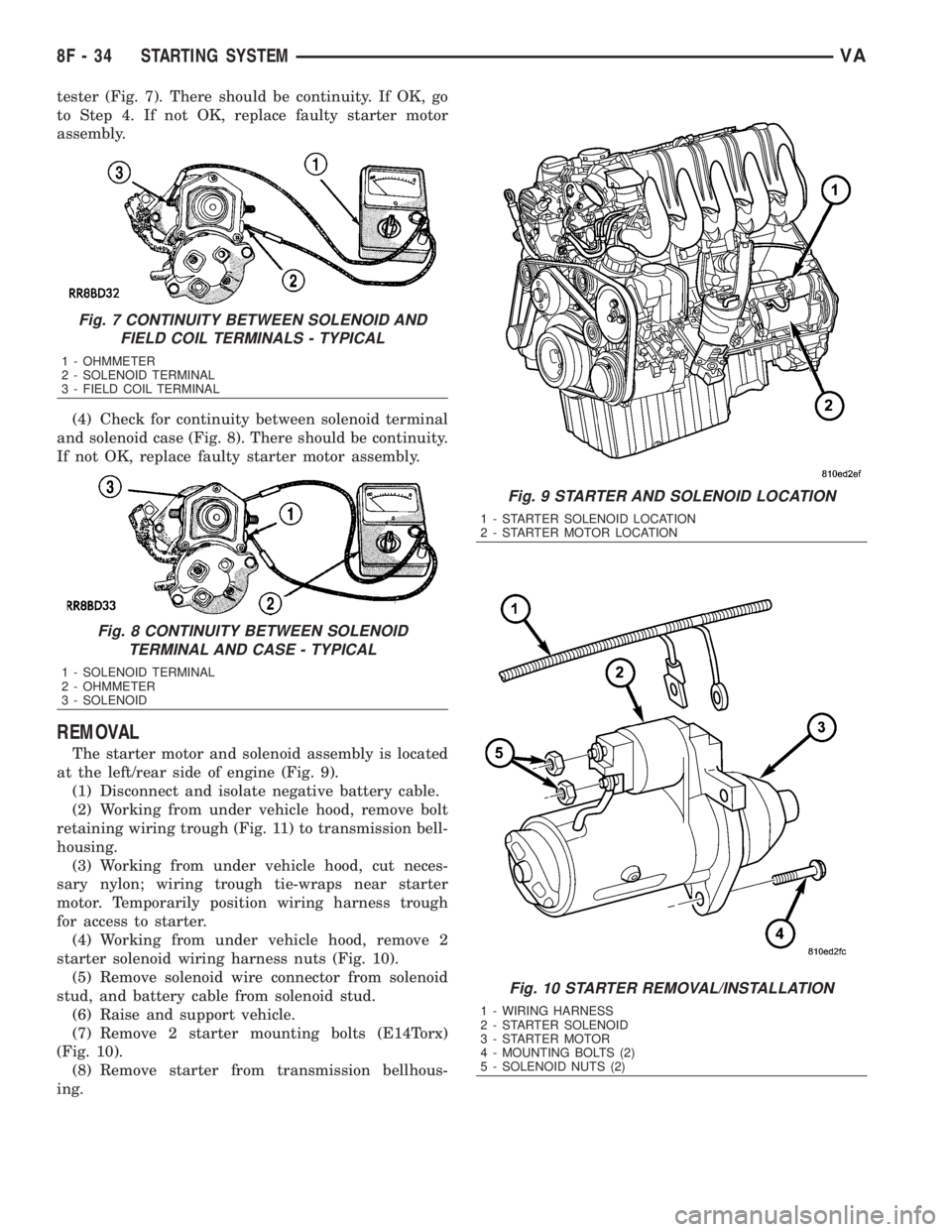
tester (Fig. 7). There should be continuity. If OK, go
to Step 4. If not OK, replace faulty starter motor
assembly.
(4) Check for continuity between solenoid terminal
and solenoid case (Fig. 8). There should be continuity.
If not OK, replace faulty starter motor assembly.
REMOVAL
The starter motor and solenoid assembly is located
at the left/rear side of engine (Fig. 9).
(1) Disconnect and isolate negative battery cable.
(2) Working from under vehicle hood, remove bolt
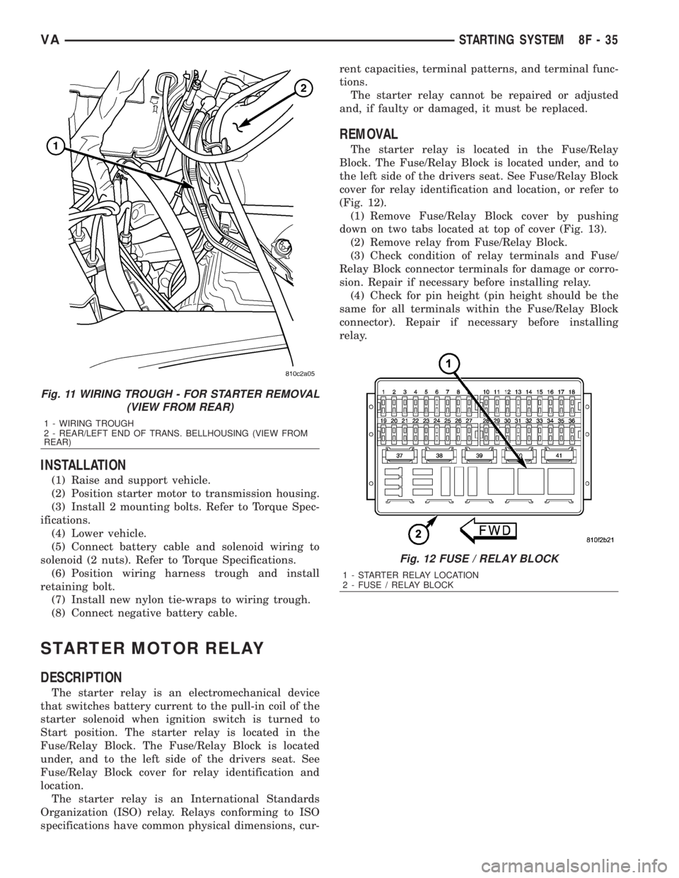
retaining wiring trough (Fig. 11) to transmission bell-
housing.
(3) Working from under vehicle hood, cut neces-
sary nylon; wiring trough tie-wraps near starter
motor. Temporarily position wiring harness trough
for access to starter.
(4) Working from under vehicle hood, remove 2
starter solenoid wiring harness nuts (Fig. 10).
(5) Remove solenoid wire connector from solenoid
stud, and battery cable from solenoid stud.
(6) Raise and support vehicle.
(7) Remove 2 starter mounting bolts (E14Torx)
(Fig. 10).
(8) Remove starter from transmission bellhous-
ing.
Fig. 7 CONTINUITY BETWEEN SOLENOID AND
FIELD COIL TERMINALS - TYPICAL
1 - OHMMETER
2 - SOLENOID TERMINAL
3 - FIELD COIL TERMINAL
Fig. 8 CONTINUITY BETWEEN SOLENOID
TERMINAL AND CASE - TYPICAL
1 - SOLENOID TERMINAL
2 - OHMMETER
3 - SOLENOID
Fig. 9 STARTER AND SOLENOID LOCATION
1 - STARTER SOLENOID LOCATION
2 - STARTER MOTOR LOCATION
Fig. 10 STARTER REMOVAL/INSTALLATION
1 - WIRING HARNESS
2 - STARTER SOLENOID
3 - STARTER MOTOR
4 - MOUNTING BOLTS (2)
5 - SOLENOID NUTS (2)
8F - 34 STARTING SYSTEMVA
Page 900 of 2305
INSTALLATION
(1) Raise and support vehicle.
(2) Position starter motor to transmission housing.
(3) Install 2 mounting bolts. Refer to Torque Spec-
ifications.
(4) Lower vehicle.
(5) Connect battery cable and solenoid wiring to
solenoid (2 nuts). Refer to Torque Specifications.
(6) Position wiring harness trough and install
retaining bolt.
(7) Install new nylon tie-wraps to wiring trough.
(8) Connect negative battery cable.
STARTER MOTOR RELAY
DESCRIPTION
The starter relay is an electromechanical device
that switches battery current to the pull-in coil of the
starter solenoid when ignition switch is turned to
Start position. The starter relay is located in the
Fuse/Relay Block. The Fuse/Relay Block is located
under, and to the left side of the drivers seat. See
Fuse/Relay Block cover for relay identification and
location.
The starter relay is an International Standards
Organization (ISO) relay. Relays conforming to ISO
specifications have common physical dimensions, cur-rent capacities, terminal patterns, and terminal func-
tions.
The starter relay cannot be repaired or adjusted
and, if faulty or damaged, it must be replaced.
REMOVAL
The starter relay is located in the Fuse/Relay
Block. The Fuse/Relay Block is located under, and to
the left side of the drivers seat. See Fuse/Relay Block
cover for relay identification and location, or refer to
(Fig. 12).
(1) Remove Fuse/Relay Block cover by pushing
down on two tabs located at top of cover (Fig. 13).
(2) Remove relay from Fuse/Relay Block.
(3) Check condition of relay terminals and Fuse/
Relay Block connector terminals for damage or corro-
sion. Repair if necessary before installing relay.
(4) Check for pin height (pin height should be the
same for all terminals within the Fuse/Relay Block
connector). Repair if necessary before installing
relay.
Fig. 11 WIRING TROUGH - FOR STARTER REMOVAL
(VIEW FROM REAR)
1 - WIRING TROUGH
2 - REAR/LEFT END OF TRANS. BELLHOUSING (VIEW FROM
REAR)
Fig. 12 FUSE / RELAY BLOCK
1 - STARTER RELAY LOCATION
2 - FUSE / RELAY BLOCK
VASTARTING SYSTEM 8F - 35
Page 921 of 2305
INSTRUMENT CLUSTER
DESCRIPTION
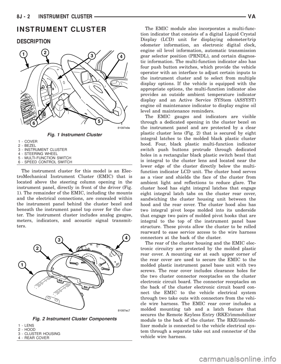
The instrument cluster for this model is an Elec-
troMechanical Instrument Cluster (EMIC) that is
located above the steering column opening in the
instrument panel, directly in front of the driver (Fig.
1). The remainder of the EMIC, including the mounts
and the electrical connections, are concealed within
the instrument panel behind the cluster bezel and
beneath the instrument panel top cover for the clus-
ter. The instrument cluster includes analog gauges,
meters, indicators, and acoustic signal transmit-
ters.The EMIC module also incorporates a multi-func-
tion indicator that consists of a digital Liquid Crystal
Display (LCD) unit for displaying odometer/trip
odometer information, an electronic digital clock,
engine oil level information, automatic transmission
gear selector position (PRNDL), and certain diagnos-
tic information. The multi-function indicator also has
four push button switches, which provide the vehicle
operator with an interface to adjust certain inputs to
the instrument cluster and to select from multiple
display options. If the vehicle is equipped with the
appropriate options, the multi-function indicator also
provides an outside ambient temperature indicator
display and an Active Service SYStem (ASSYST)
engine oil maintenance indicator to display engine oil
level and maintenance reminders.
The EMIC gauges and indicators are visible
through a dedicated opening in the cluster bezel on
the instrument panel and are protected by a clear
plastic cluster lens (Fig. 2) that is secured by eight
integral latches to the molded black plastic cluster
hood. Four, black plastic multi-function indicator
switch push buttons protrude through dedicated
holes in a rectangular black plastic switch bezel that
is integral to the cluster lens and located near the
lower edge of the cluster directly below the multi-
function indicator LCD unit. The cluster hood serves
as a visor and shields the face of the cluster from
ambient light and reflections to reduce glare. The
cluster hood has eight integral latches that engage
eight integral latch tabs on the cluster rear cover,
sandwiching the cluster housing unit between the
hood and the rear cover. The cluster hood also has
two integral pivot loops molded into its underside
that engage two pairs of molded pivot hooks that are
integral to the top of the instrument panel base
structure. These pivots allow the cluster to be rolled
rearward to ease service access to the wire harness
connectors at the back of the cluster.
The rear of the cluster housing and the EMIC elec-
tronic circuitry are protected by the molded plastic
rear cover. A mounting ear at each upper corner of
the rear cover are used to secure the EMIC to the
molded plastic instrument panel base unit with two
screws. The rear cover includes clearance holes for
the two cluster connector receptacles on the cluster
electronic circuit board. The connector receptacles on
the back of the cluster electronic circuit board con-
nect the EMIC to the vehicle electrical system
through two take outs with connectors from the vehi-
cle wire harness. The EMIC rear cover includes a
molded mounting tab and a latch feature that
secures the Remote Keyless Entry (RKE)/immobilizer
module to the back of the cluster. The RKE/immobi-
lizer module is connected to the vehicle electrical sys-
tem through a separate take out and connector of the
vehicle wire harness.
Fig. 1 Instrument Cluster
1 - COVER
2 - BEZEL
3 - INSTRUMENT CLUSTER
4 - STEERING WHEEL
5 - MULTI-FUNCTION SWITCH
6 - SPEED CONTROL SWITCH
Fig. 2 Instrument Cluster Components
1 - LENS
2 - HOOD
3 - CLUSTER HOUSING
4 - REAR COVER
8J - 2 INSTRUMENT CLUSTERVA
Page 1214 of 2305
8W-30 FUEL/IGNITION SYSTEM
Component Page
Accelerator Pedal Position Sensor.... 8W-30-10, 21
Airbag Control Module................ 8W-30-9
Boost Pressure Sensor............. 8W-30-9, 25
Boost Pressure Servomotor............ 8W-30-24
Boost Pressure Solenoid.............. 8W-30-14
Camshaft Position Sensor.............. 8W-30-6
Central Timer Module................ 8W-30-9
Crankcase Heater................ 8W-30-17, 24
Crankshaft Position Sensor............ 8W-30-7
Data Link Connector................. 8W-30-4
Daytime Running Lamps Relay......... 8W-30-2
EGR Valve..................... 8W-30-17, 24
Engine Control Module . . . 8W-30-2, 4, 5, 6, 7, 8, 9,
10, 11, 12, 13, 14, 15, 16, 17,
18, 19, 20, 21, 22, 23, 24, 25
Engine Control Relay........... 8W-30-8, 17, 24
Engine Coolant Level Switch........... 8W-30-3
Engine Coolant Temperature Sensor..... 8W-30-6
Engine Oil Sensor................... 8W-30-17
Fuel Injector No. 1............... 8W-30-15, 22
Fuel Injector No. 2............... 8W-30-16, 23
Fuel Injector No. 3............... 8W-30-15, 22
Fuel Injector No. 4............... 8W-30-15, 22
Fuel Injector No. 5............... 8W-30-16, 23
Fuel Level Sensor.................... 8W-30-3
Fuel Pressure Sensor................. 8W-30-5
Fuel Pressure Solenoid................ 8W-30-7
Fuel Pump........................ 8W-30-18
Fuel Pump Relay................... 8W-30-18
Fuel Quantity Control Valve........... 8W-30-7
Fuel Shutdown Solenoid............... 8W-30-7
Fuel Temperature Sensor.............. 8W-30-5
Fuse 5......................... 8W-30-13, 19
Fuse 7............................ 8W-30-20
Fuse 12............................ 8W-30-2Component Page
Fuse 16............................ 8W-30-8
Fuse 17........................ 8W-30-17, 24
Fuse 18............................ 8W-30-9
Fuse 19........................... 8W-30-18
Fuse Block No. 1....... 8W-30-8, 9, 17, 18, 20, 24
Fuse Block No. 3.................... 8W-30-2
G100........................ 8W-30-3, 13, 19
G103............................. 8W-30-17
G200........................... 8W-30-8, 12
G202............................. 8W-30-18
G203.............................. 8W-30-2
Glow Plug Control Module......... 8W-30-13, 19
Glow Plug No. 1................. 8W-30-13, 19
Glow Plug No. 2................. 8W-30-13, 19
Glow Plug No. 3................. 8W-30-13, 19
Glow Plug No. 4................. 8W-30-13, 19
Glow Plug No. 5................. 8W-30-13, 19
High Idle Switch.................... 8W-30-2
Instrument Cluster................... 8W-30-3
Intake Air Pressure Sensor............ 8W-30-20
Intake Air Temperature Sensor...... 8W-30-10, 21
Kickdown Switch................... 8W-30-12
Low Fuel Pressure Sensor............ 8W-30-11
Mass Air Flow Sensor............. 8W-30-14, 20
Optional Equipment Relay............. 8W-30-2
Oxygen Sensor..................... 8W-30-24
Power Distribution Center......... 8W-30-13, 19
Relay Block........................ 8W-30-2
Speed Control Switch................ 8W-30-12
Starter Motor Relay.............. 8W-30-11, 18
Transmission Control Module........... 8W-30-4
Water In Fuel Sensor............. 8W-30-11, 25
Wiper/Turn Signal/Engine Start Control
Module.......................... 8W-30-8
VA8W-30 FUEL/IGNITION SYSTEM 8W - 30 - 1
Page 1493 of 2305
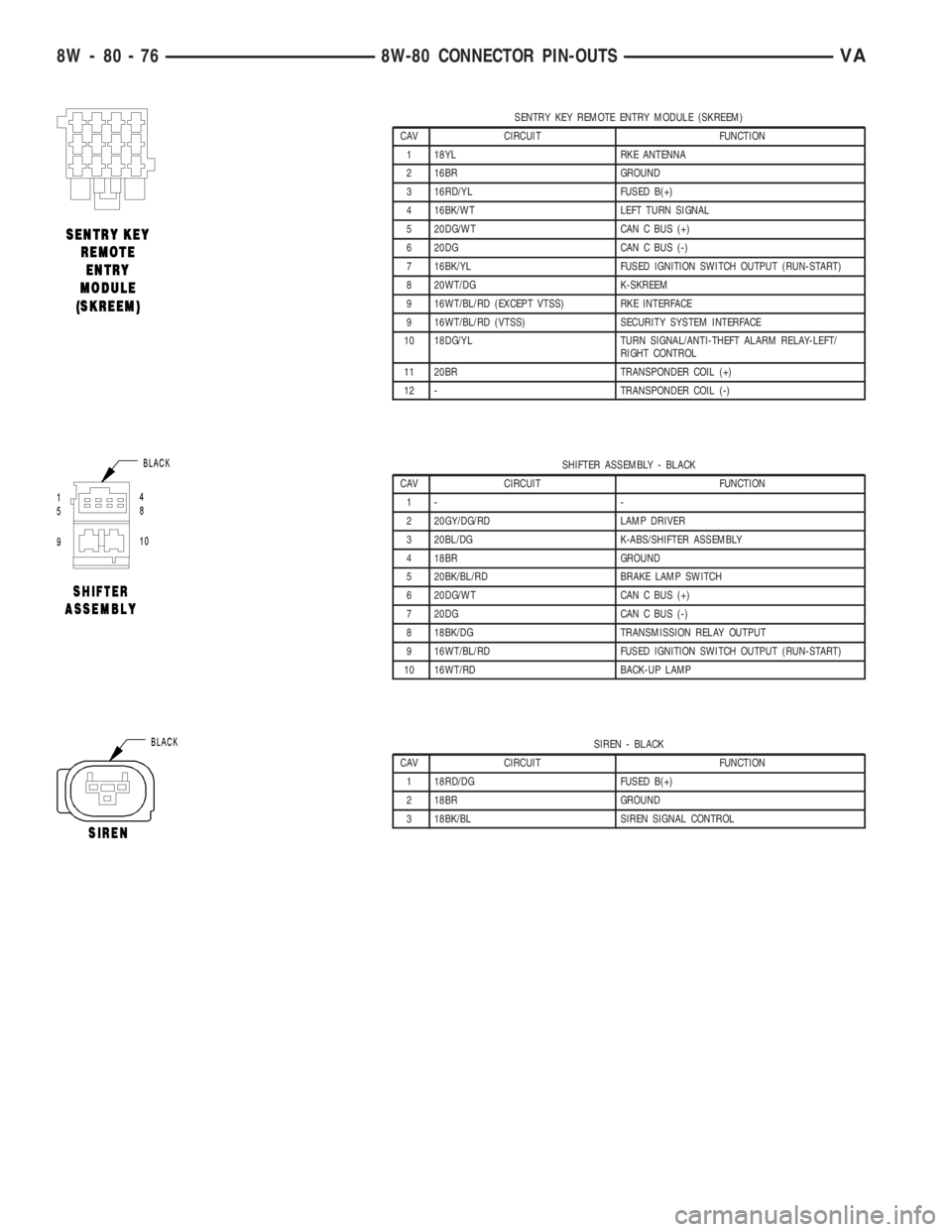
SENTRY KEY REMOTE ENTRY MODULE (SKREEM)
CAV CIRCUIT FUNCTION
1 18YL RKE ANTENNA
2 16BR GROUND
3 16RD/YL FUSED B(+)
4 16BK/WT LEFT TURN SIGNAL
5 20DG/WT CAN C BUS (+)
6 20DG CAN C BUS (-)
7 16BK/YL FUSED IGNITION SWITCH OUTPUT (RUN-START)
8 20WT/DG K-SKREEM
9 16WT/BL/RD (EXCEPT VTSS) RKE INTERFACE
9 16WT/BL/RD (VTSS) SECURITY SYSTEM INTERFACE
10 18DG/YL TURN SIGNAL/ANTI-THEFT ALARM RELAY-LEFT/
RIGHT CONTROL
11 20BR TRANSPONDER COIL (+)
12 - TRANSPONDER COIL (-)
SHIFTER ASSEMBLY - BLACK
CAV CIRCUIT FUNCTION
1- -
2 20GY/DG/RD LAMP DRIVER
3 20BL/DG K-ABS/SHIFTER ASSEMBLY
4 18BR GROUND
5 20BK/BL/RD BRAKE LAMP SWITCH
6 20DG/WT CAN C BUS (+)
7 20DG CAN C BUS (-)
8 18BK/DG TRANSMISSION RELAY OUTPUT
9 16WT/BL/RD FUSED IGNITION SWITCH OUTPUT (RUN-START)
10 16WT/RD BACK-UP LAMP
SIREN - BLACK
CAV CIRCUIT FUNCTION
1 18RD/DG FUSED B(+)
2 18BR GROUND
3 18BK/BL SIREN SIGNAL CONTROL
8W - 80 - 76 8W-80 CONNECTOR PIN-OUTSVA
Page 1581 of 2305
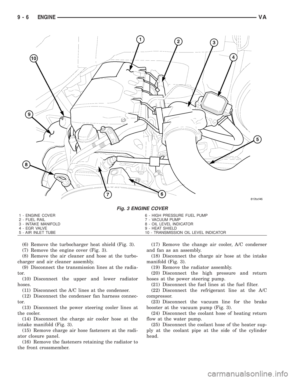
(6) Remove the turbocharger heat shield (Fig. 3).
(7) Remove the engine cover (Fig. 3).
(8) Remove the air cleaner and hose at the turbo-
charger and air cleaner assembly.
(9) Disconnect the transmission lines at the radia-
tor.
(10) Disconnect the upper and lower radiator
hoses.
(11) Disconnect the A/C lines at the condenser.
(12) Disconnect the condenser fan harness connec-
tor.
(13) Disconnect the power steering cooler lines at
the cooler.
(14) Disconnect the charge air cooler hose at the
intake manifold (Fig. 3).
(15) Remove charge air hose fasteners at the radi-
ator closure panel.
(16) Remove the fasteners retaining the radiator to
the front crossmember.(17) Remove the change air cooler, A/C conderser
and fan as an assembly.
(18) Disconnect the charge air hose at the intake
manifold (Fig. 3).
(19) Remove the radiator assembly.
(20) Disconnect the high pressure and return
hoses at the power steering pump.
(21) Disconnect the fuel lines at the fuel filter.
(22) Disconnect the refrigerant line at the A/C
compressor.
(23) Disconnect the vacuum line for the brake
booster at the vacuum pump (Fig. 3).
(24) Disconnect the coolant hose of heating return
flow at the water pump.
(25) Disconnect the coolant hose of the heater sup-
ply at the coolant pipe at the side of the cylinder
head.
Fig. 3 ENGINE COVER
1 - ENGINE COVER 6 - HIGH PRESSURE FUEL PUMP
2 - FUEL RAIL 7 - VACUUM PUMP
3 - INTAKE MANIFOLD 8 - OIL LEVEL INDICATOR
4 - EGR VALVE 9 - HEAT SHIELD
5 - AIR INLET TUBE 10 - TRANSMISSION OIL LEVEL INDICATOR
9 - 6 ENGINEVA