2006 MERCEDES-BENZ SPRINTER tire pressure
[x] Cancel search: tire pressurePage 1731 of 2305
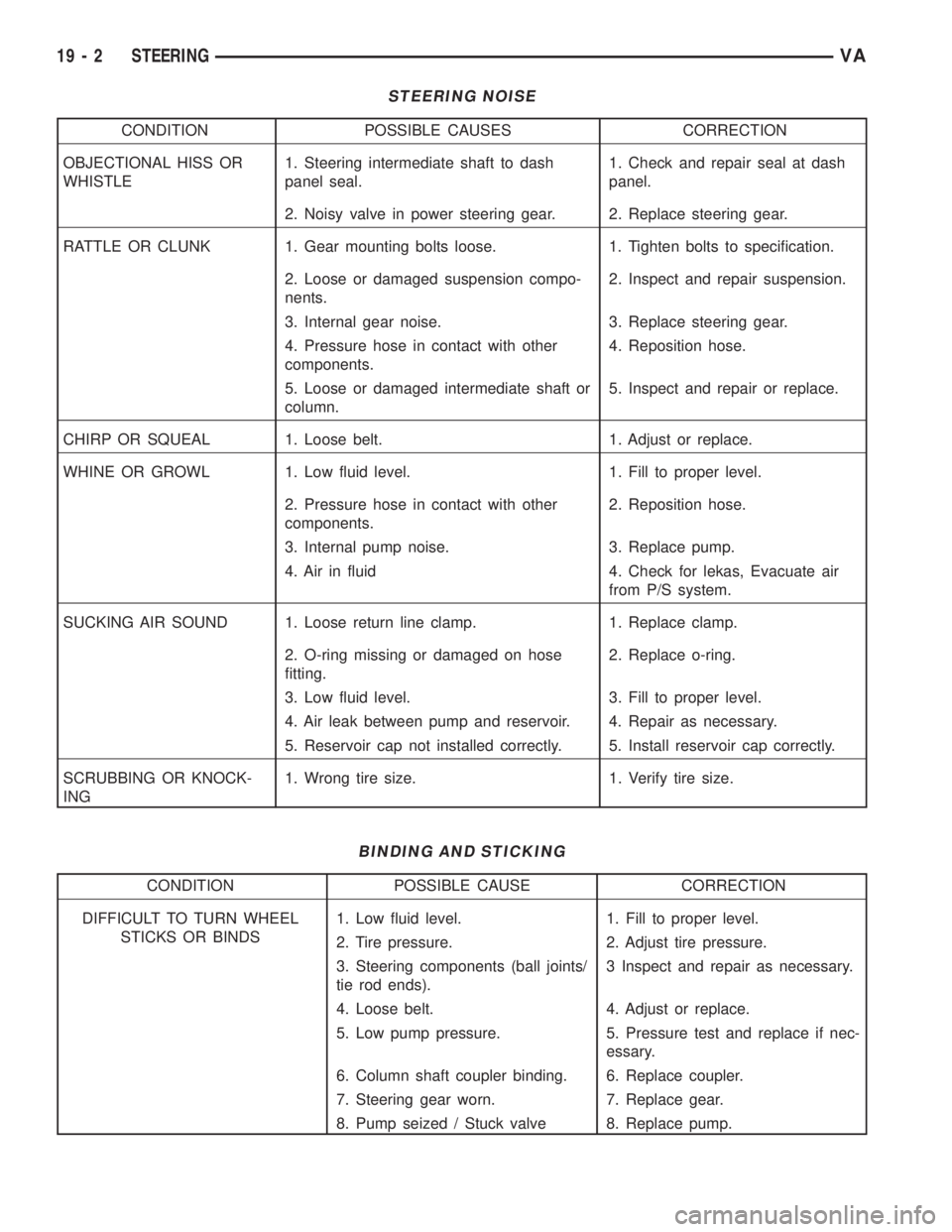
STEERING NOISE
CONDITION POSSIBLE CAUSES CORRECTION
OBJECTIONAL HISS OR
WHISTLE1. Steering intermediate shaft to dash
panel seal.1. Check and repair seal at dash
panel.
2. Noisy valve in power steering gear. 2. Replace steering gear.
RATTLE OR CLUNK 1. Gear mounting bolts loose. 1. Tighten bolts to specification.
2. Loose or damaged suspension compo-
nents.2. Inspect and repair suspension.
3. Internal gear noise. 3. Replace steering gear.
4. Pressure hose in contact with other
components.4. Reposition hose.
5. Loose or damaged intermediate shaft or
column.5. Inspect and repair or replace.
CHIRP OR SQUEAL 1. Loose belt. 1. Adjust or replace.
WHINE OR GROWL 1. Low fluid level. 1. Fill to proper level.
2. Pressure hose in contact with other
components.2. Reposition hose.
3. Internal pump noise. 3. Replace pump.
4. Air in fluid 4. Check for lekas, Evacuate air
from P/S system.
SUCKING AIR SOUND 1. Loose return line clamp. 1. Replace clamp.
2. O-ring missing or damaged on hose
fitting.2. Replace o-ring.
3. Low fluid level. 3. Fill to proper level.
4. Air leak between pump and reservoir. 4. Repair as necessary.
5. Reservoir cap not installed correctly. 5. Install reservoir cap correctly.
SCRUBBING OR KNOCK-
ING1. Wrong tire size. 1. Verify tire size.
BINDING AND STICKING
CONDITION POSSIBLE CAUSE CORRECTION
DIFFICULT TO TURN WHEEL
STICKS OR BINDS1. Low fluid level. 1. Fill to proper level.
2. Tire pressure. 2. Adjust tire pressure.
3. Steering components (ball joints/
tie rod ends).3 Inspect and repair as necessary.
4. Loose belt. 4. Adjust or replace.
5. Low pump pressure. 5. Pressure test and replace if nec-
essary.
6. Column shaft coupler binding. 6. Replace coupler.
7. Steering gear worn. 7. Replace gear.
8. Pump seized / Stuck valve 8. Replace pump.
19 - 2 STEERINGVA
Page 1732 of 2305
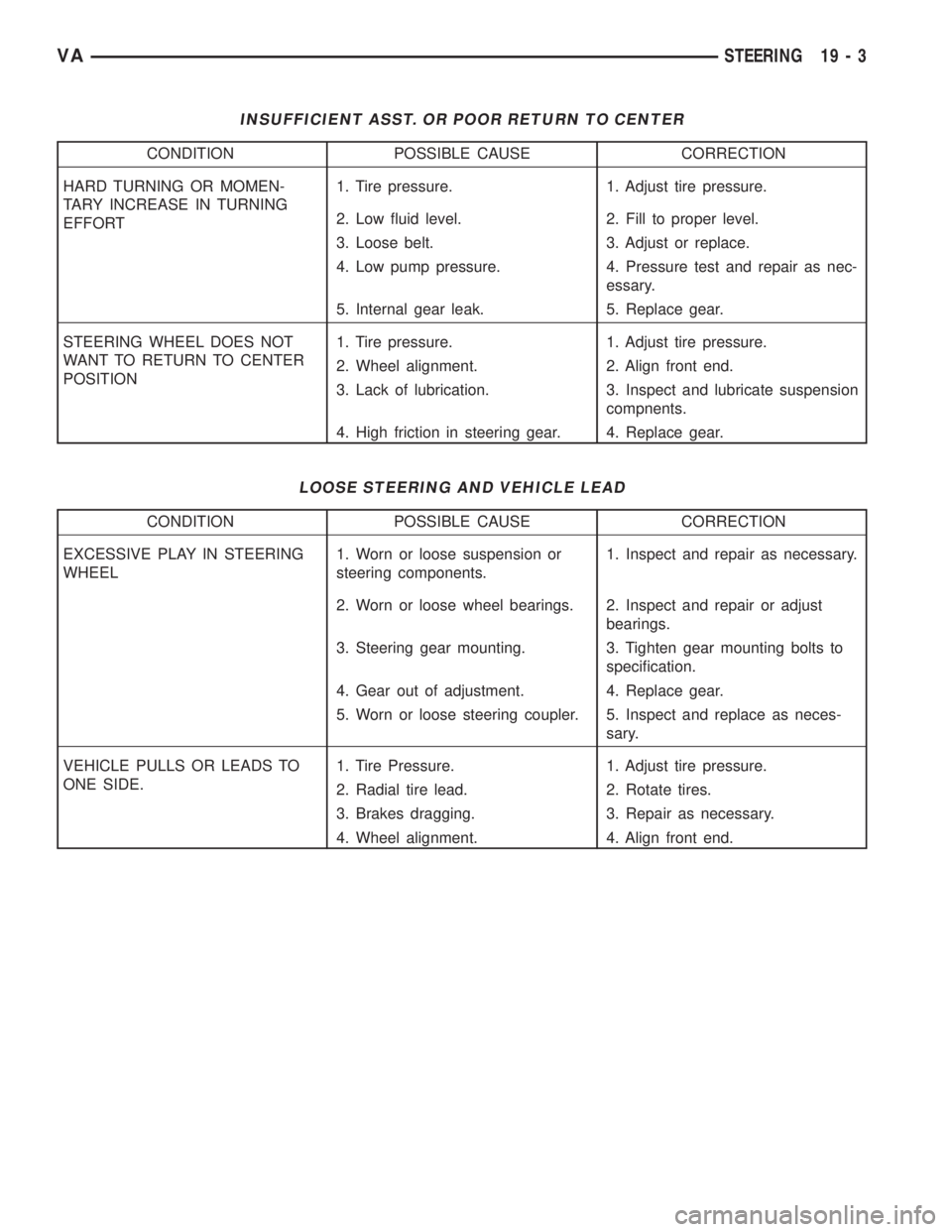
INSUFFICIENT ASST. OR POOR RETURN TO CENTER
CONDITION POSSIBLE CAUSE CORRECTION
HARD TURNING OR MOMEN-
TARY INCREASE IN TURNING
EFFORT1. Tire pressure. 1. Adjust tire pressure.
2. Low fluid level. 2. Fill to proper level.
3. Loose belt. 3. Adjust or replace.
4. Low pump pressure. 4. Pressure test and repair as nec-
essary.
5. Internal gear leak. 5. Replace gear.
STEERING WHEEL DOES NOT
WANT TO RETURN TO CENTER
POSITION1. Tire pressure. 1. Adjust tire pressure.
2. Wheel alignment. 2. Align front end.
3. Lack of lubrication. 3. Inspect and lubricate suspension
compnents.
4. High friction in steering gear. 4. Replace gear.
LOOSE STEERING AND VEHICLE LEAD
CONDITION POSSIBLE CAUSE CORRECTION
EXCESSIVE PLAY IN STEERING
WHEEL1. Worn or loose suspension or
steering components.1. Inspect and repair as necessary.
2. Worn or loose wheel bearings. 2. Inspect and repair or adjust
bearings.
3. Steering gear mounting. 3. Tighten gear mounting bolts to
specification.
4. Gear out of adjustment. 4. Replace gear.
5. Worn or loose steering coupler. 5. Inspect and replace as neces-
sary.
VEHICLE PULLS OR LEADS TO
ONE SIDE.1. Tire Pressure. 1. Adjust tire pressure.
2. Radial tire lead. 2. Rotate tires.
3. Brakes dragging. 3. Repair as necessary.
4. Wheel alignment. 4. Align front end.
VASTEERING 19 - 3
Page 1784 of 2305

CONDITION POSSIBLE CAUSES CORRECTION
HARD 3-2 DOWNSHIFT
WHEN DECELERATION
EVEN AFTER READAP-
TION1. K3 Idles. 1. Install TCM And/Or Electro-
hydraulic Control Unit.
NO RESP. DELAYED UP-
SHIFT, NO DTC1. Different Tire Sizes Are Mounted
On The Front Axle.1. Mount Uniform Tire Sizes
On The Front Axle.
NO UPSHIFT 3-4, 4-5 AF-
TER FAST OFF (ACCEL-
ERATOR)1. Upshift Prevention To Realize Dy-
namical Drivestyle.1. Instruct Customer.
NO UPSHIFT OF 1ST
GEAR BELOW 5000 RPM1. Gear Recognition Switch. 1. Replace Gear Recognition
Switch.
NO UPSHIFT INTO 5TH
GEAR WHEN FULL
THROTTLE OR KICK
DOWN ACTIVATION1. The Upshift 4-5 At Full Throttle or
Kick Down Never Occurs Until
Reaching Cut Off Speed. Under
These Conditions, The High Pow-
ered Vehicle Will Never Shift Into
5th Gear Below 250 km/h.1. Instruct Customer.
NO KICK DOWN SHIFT-
ING1. Accelerator Pedal Value < 95%. 1. Check Engine Control. Ad-
just As Necessary.
Engine Turns Up While 2-3
Upshift and/or Hard 3-2
Downshift1. Oil Level Too Low. 1. Check Oil Level. Add if Nec-
essary.
2. Oil Filter Not Installed. 2. Install Oil Filter.
3. Free Wheeling Clutch F2 Defec-
tive.3. Replace Free Wheeling
Clutch F2, Hollow Shaft, and
Rear Sun Gear/Inner Disc Car-
rier K3.
GRABBING 2-3 COAST-
ING UPSHIFT AND/OR
BRAKE DOWNSHIFT1. Oil Level Too Low. 1. Check Oil Level. Add if Nec-
essary.
2. Oil Filter Not Installed. 2. Install Oil Filter.
3. Control shift or Command Valve
Blocked.3. Check Each Slide Valve For
Base Position and Ease Of
Movement, Remove Particle.
4. K3 Disc Burnt, Hot Spots or
Rubbed Down.4. Replace Inner and Outer
Disc Carrier K3 And Control
Valve.
DELAYED ENGAGEMENT,
NO TRANSFER OF POW-
ER IN R AND/OR D, ALSO
AT TIMES1. Oil Level Too Low. 1. Check Oil Level. Add if Nec-
essary.
2. Recognition Switch - Selector Le-
ver Position.2. Replace Recognition Switch
Only When Intermediate Posi-
tion or Fault is Indicated.
3. Oil Filter Not Installed. 3. Install Oil Filter.
4. AEV, Delayed Pressure Build Up
On Piston B2/B3.4. Install New Shifting Proce-
dure (TCM, electrohydraulic
control unit or repair set).
5. Wrong Combination TCM/Electro-
hydraulic Control Unit.5. Check Combination TCM/
Electrohydraulic Control Unit.
Replace TCM Resp. Electrohy-
draulic Control Unit, if neces-
sary.
VAAUTOMATIC TRANSMISSION NAG1 - SERVICE INFORMATION 21 - 41
Page 1848 of 2305
(0.114 in.), 3.2 mm (0.126 in.), and 3.5 mm (0.138
in.).
ELECTROHYDRAULIC UNIT
DESCRIPTION
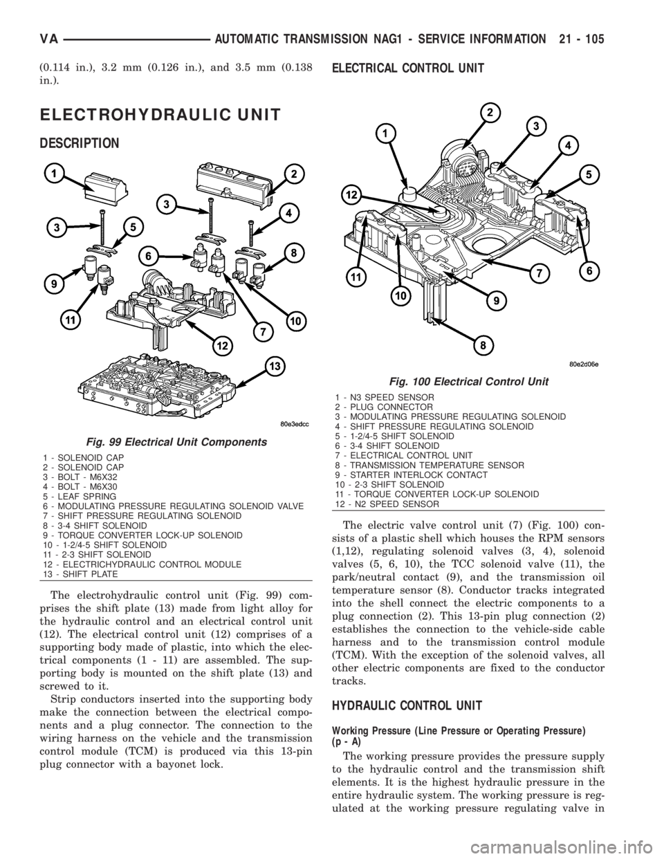
The electrohydraulic control unit (Fig. 99) com-
prises the shift plate (13) made from light alloy for
the hydraulic control and an electrical control unit
(12). The electrical control unit (12) comprises of a
supporting body made of plastic, into which the elec-
trical components (1 - 11) are assembled. The sup-
porting body is mounted on the shift plate (13) and
screwed to it.
Strip conductors inserted into the supporting body
make the connection between the electrical compo-
nents and a plug connector. The connection to the
wiring harness on the vehicle and the transmission
control module (TCM) is produced via this 13-pin
plug connector with a bayonet lock.
ELECTRICAL CONTROL UNIT
The electric valve control unit (7) (Fig. 100) con-
sists of a plastic shell which houses the RPM sensors
(1,12), regulating solenoid valves (3, 4), solenoid
valves (5, 6, 10), the TCC solenoid valve (11), the
park/neutral contact (9), and the transmission oil
temperature sensor (8). Conductor tracks integrated
into the shell connect the electric components to a
plug connection (2). This 13-pin plug connection (2)
establishes the connection to the vehicle-side cable
harness and to the transmission control module
(TCM). With the exception of the solenoid valves, all
other electric components are fixed to the conductor
tracks.
HYDRAULIC CONTROL UNIT
Working Pressure (Line Pressure or Operating Pressure)
(p-A)
The working pressure provides the pressure supply
to the hydraulic control and the transmission shift
elements. It is the highest hydraulic pressure in the
entire hydraulic system. The working pressure is reg-
ulated at the working pressure regulating valve in
Fig. 99 Electrical Unit Components
1 - SOLENOID CAP
2 - SOLENOID CAP
3 - BOLT - M6X32
4 - BOLT - M6X30
5 - LEAF SPRING
6 - MODULATING PRESSURE REGULATING SOLENOID VALVE
7 - SHIFT PRESSURE REGULATING SOLENOID
8 - 3-4 SHIFT SOLENOID
9 - TORQUE CONVERTER LOCK-UP SOLENOID
10 - 1-2/4-5 SHIFT SOLENOID
11 - 2-3 SHIFT SOLENOID
12 - ELECTRICHYDRAULIC CONTROL MODULE
13 - SHIFT PLATE
Fig. 100 Electrical Control Unit
1 - N3 SPEED SENSOR
2 - PLUG CONNECTOR
3 - MODULATING PRESSURE REGULATING SOLENOID
4 - SHIFT PRESSURE REGULATING SOLENOID
5 - 1-2/4-5 SHIFT SOLENOID
6 - 3-4 SHIFT SOLENOID
7 - ELECTRICAL CONTROL UNIT
8 - TRANSMISSION TEMPERATURE SENSOR
9 - STARTER INTERLOCK CONTACT
10 - 2-3 SHIFT SOLENOID
11 - TORQUE CONVERTER LOCK-UP SOLENOID
12 - N2 SPEED SENSOR
VAAUTOMATIC TRANSMISSION NAG1 - SERVICE INFORMATION 21 - 105
Page 1928 of 2305
TIRES / WHEELS
TABLE OF CONTENTS
page page
TIRES/WHEELS
DIAGNOSIS AND TESTING - TIRE AND
WHEEL RUNOUT......................1
STANDARD PROCEDURE
STANDARD PROCEDURE - MATCH
MOUNTING...........................2
STANDARD PROCEDURE - TIRE AND
WHEEL BALANCE......................4
STANDARD PROCEDURE - TIRE ROTATION . 6
SPECIFICATIONS
TORQUE CHART......................7
TIRES
DESCRIPTION
DESCRIPTION - TIRES..................7
DESCRIPTION - RADIAL ± PLY TIRES......7
DESCRIPTION - TIRE PRESSURE FOR
HIGH SPEEDS.........................8
DESCRIPTION - REPLACEMENT TIRES.....8
DESCRIPTION - TIRE INFLATION
PRESSURES..........................8
DIAGNOSIS AND TESTING
DIAGNOSIS AND TESTING - PRESSURE
GAUGES.............................9
DIAGNOSIS AND TESTING - TIRE NOISE
OR VIBRATION........................9
DIAGNOSIS AND TESTING - TREAD WEAR
INDICATORS..........................9DIAGNOSIS AND TESTING - TIRE WEAR
PATTERNS...........................9
DIAGNOSIS AND TESTING - TIRE/VEHICLE
LEAD...............................10
STANDARD PROCEDURE - REPAIRING
LEAKS..............................12
CLEANING............................12
SPECIFICATIONS
TIRES..............................12
SPARE TIRE CARRIER
REMOVAL.............................12
INSTALLATION.........................12
WHEELS
DESCRIPTION.........................13
OPERATION...........................13
DIAGNOSIS AND TESTING
WHEEL INSPECTION..................13
STANDARD PROCEDURE
STANDARD PROCEDURE - WHEEL
REPLACEMENT.......................13
STANDARD PROCEDURE - DUAL REAR
WHEEL INSTALLATION.................13
REMOVAL.............................14
INSTALLATION.........................15
TIRES / WHEELS
DIAGNOSIS AND TESTING - TIRE AND WHEEL
RUNOUT
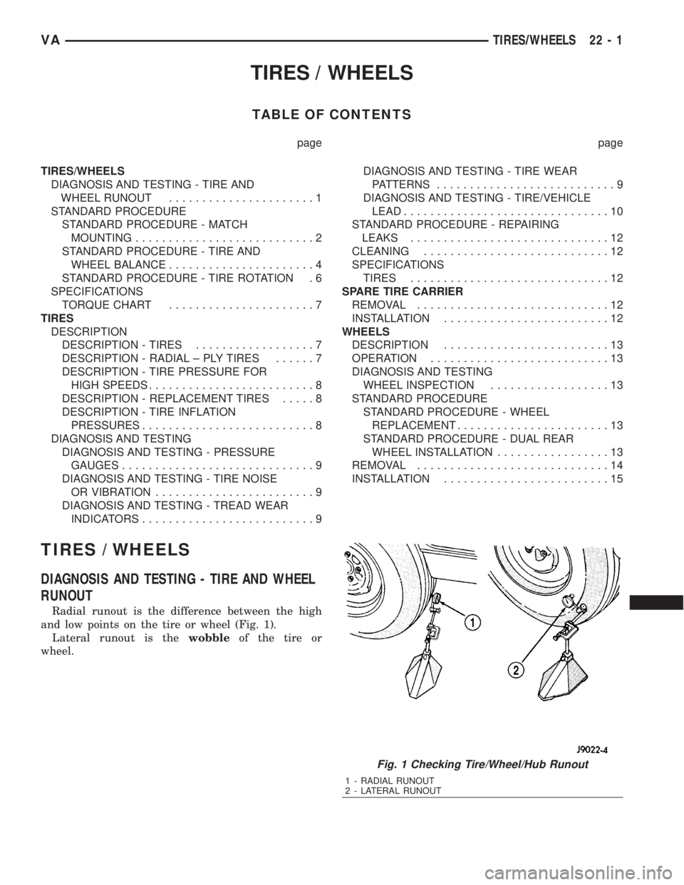
Radial runout is the difference between the high
and low points on the tire or wheel (Fig. 1).
Lateral runout is thewobbleof the tire or
wheel.
Fig. 1 Checking Tire/Wheel/Hub Runout
1 - RADIAL RUNOUT
2 - LATERAL RUNOUT
VATIRES/WHEELS 22 - 1
Page 1935 of 2305
Radial-ply tires must always be used in sets of
four. Under no circumstances should they be used on
the front only. They may be mixed with temporary
spare tires when necessary. A maximum speed of 50
MPH is recommended while a temporary spare is in
use.
Radial-ply tires have the same load-carrying capac-
ity as other types of tires of the same size. They also
use the same recommended inflation pressures.
The use of oversized tires, either in the front or
rear of the vehicle, can cause vehicle drive train fail-
ure. This could also cause inaccurate wheel speed
signals when the vehicle is equipped with Anti-Lock
Brakes.
The use of tires from different manufactures on the
same vehicle is NOT recommended. The proper tire
pressure should be maintained on all four tires.
DESCRIPTION - TIRE PRESSURE FOR HIGH
SPEEDS
Where speed limits allow the vehicle to be driven
at high speeds, correct tire inflation pressure is very
important. For speeds up to and including 120 km/h
(75 mph), tires must be inflated to the pressures
shown on the tire placard. For continuous speeds in
excess of 120 km/h (75 mph), tires must be inflated
to the maximum pressure specified on the tire side-
wall.
Vehicles loaded to the maximum capacity should
not be driven at continuous speeds above 75 mph
(120 km/h).
For emergency vehicles that are driven at speeds
over 90 mph (144 km/h), special high speed tires
must be used. Consult tire manufacturer for correct
inflation pressure recommendations.
DESCRIPTION - REPLACEMENT TIRES
The original equipment tires provide a proper bal-
ance of many characteristics such as:
²Ride
²Noise
²Handling
²Durability
²Tread life
²Traction
²Rolling resistance
²Speed capability
It is recommended that tires equivalent to the orig-
inal equipment tires be used when replacement is
needed.
Failure to use equivalent replacement tires may
adversely affect the safety and handling of the vehi-
cle.The use of oversize tires may cause interference
with vehicle components. Under extremes of suspen-
sion and steering travel, interference with vehicle
components may cause tire damage.
WARNING: FAILURE TO EQUIP THE VEHICLE WITH
TIRES HAVING ADEQUATE SPEED CAPABILITY
CAN RESULT IN SUDDEN TIRE FAILURE.
DESCRIPTION - TIRE INFLATION PRESSURES
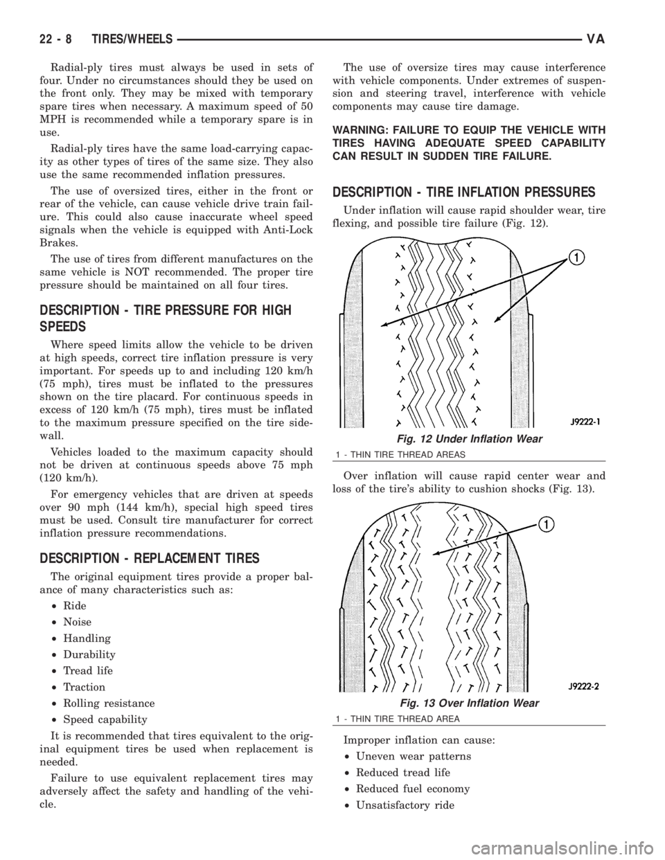
Under inflation will cause rapid shoulder wear, tire
flexing, and possible tire failure (Fig. 12).
Over inflation will cause rapid center wear and
loss of the tire's ability to cushion shocks (Fig. 13).
Improper inflation can cause:
²Uneven wear patterns
²Reduced tread life
²Reduced fuel economy
²Unsatisfactory ride
Fig. 12 Under Inflation Wear
1 - THIN TIRE THREAD AREAS
Fig. 13 Over Inflation Wear
1 - THIN TIRE THREAD AREA
22 - 8 TIRES/WHEELSVA
Page 1936 of 2305
²Vehicle drift
For proper tire pressure specification refer to the
Tire Inflation Pressure Chart provided with the vehi-
cles Owners Manual. A Certification Label on the
drivers side door pillar provides the minimum tire
and rim size for the vehicle. The label also list the
cold inflation pressure for these tires at full load
operation
Tire pressures have been chosen to provide safe
operation, vehicle stability, and a smooth ride. Tire
pressure should be checked cold once a month. Tire
pressure decreases as the ambient temperature
drops. Check tire pressure frequently when ambient
temperature varies widely.
Tire inflation pressures are cold inflation pressure.
The vehicle must sit for at least 3 hours to obtain the
correct cold inflation pressure reading. Or be driven
less than one mile after sitting for 3 hours. Tire
inflation pressures may increase from 2 to 6 pounds
per square inch (psi) during operation. Do not reduce
this normal pressure build-up.
WARNING: OVER OR UNDER INFLATED TIRES CAN
AFFECT VEHICLE HANDLING AND TREAD WEAR.
THIS MAY CAUSE THE TIRE TO FAIL SUDDENLY,
RESULTING IN LOSS OF VEHICLE CONTROL.
DIAGNOSIS AND TESTING
DIAGNOSIS AND TESTING - PRESSURE
GAUGES
A quality air pressure gauge is recommended to
check tire pressure. After checking the air pressure,
replace valve cap finger tight.
DIAGNOSIS AND TESTING - TIRE NOISE OR
VIBRATION
Radial-ply tires are sensitive to force impulses
caused by improper mounting, vibration, wheel
defects, or possibly tire imbalance.
To find out if tires are causing the noise or vibra-
tion, drive the vehicle over a smooth road at varying
speeds. Note the noise level during acceleration and
deceleration. The engine, differential and exhaust
noises will change as speed varies, while the tire
noise will usually remain constant.
DIAGNOSIS AND TESTING - TREAD WEAR
INDICATORS
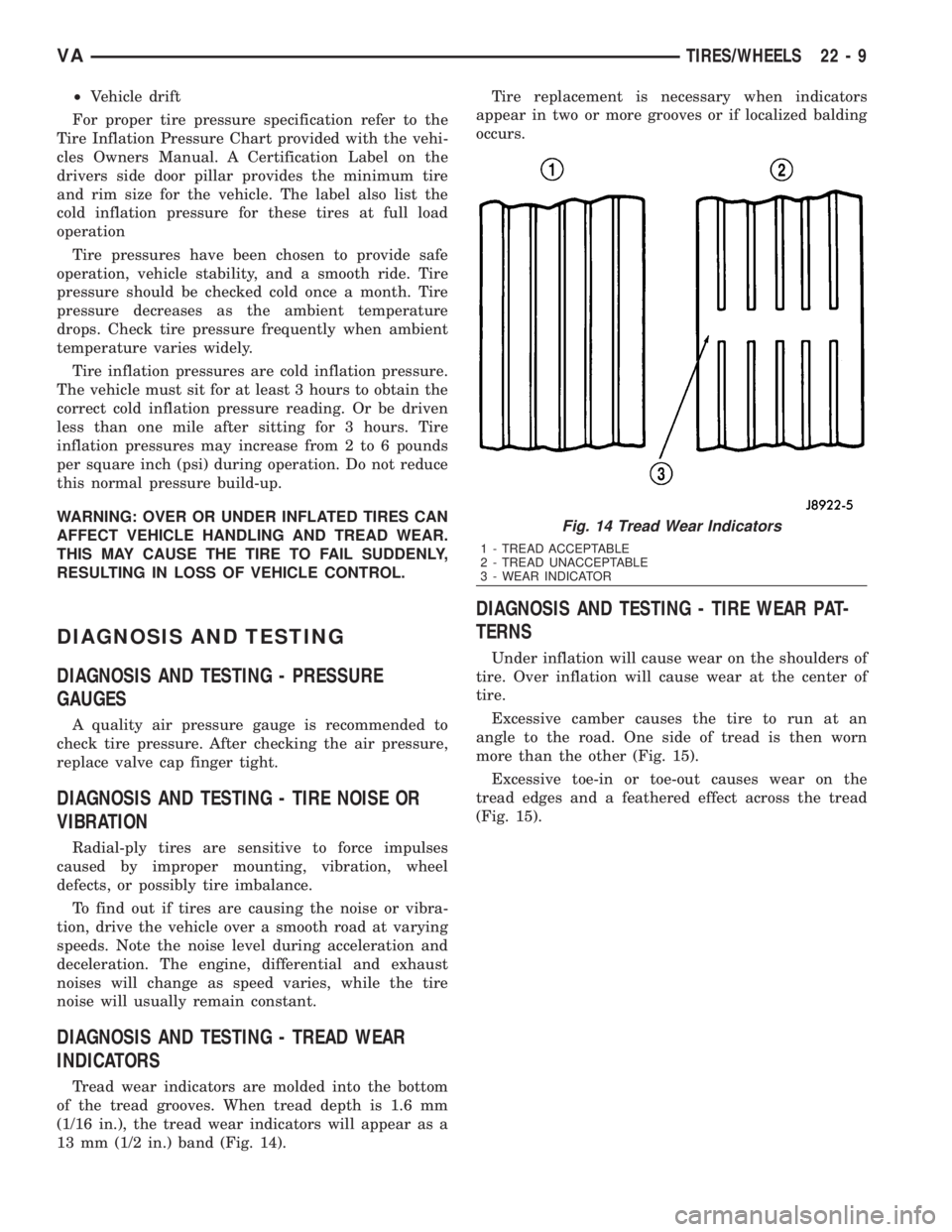
Tread wear indicators are molded into the bottom
of the tread grooves. When tread depth is 1.6 mm
(1/16 in.), the tread wear indicators will appear as a
13 mm (1/2 in.) band (Fig. 14).Tire replacement is necessary when indicators
appear in two or more grooves or if localized balding
occurs.
DIAGNOSIS AND TESTING - TIRE WEAR PAT-
TERNS
Under inflation will cause wear on the shoulders of
tire. Over inflation will cause wear at the center of
tire.
Excessive camber causes the tire to run at an
angle to the road. One side of tread is then worn
more than the other (Fig. 15).
Excessive toe-in or toe-out causes wear on the
tread edges and a feathered effect across the tread
(Fig. 15).
Fig. 14 Tread Wear Indicators
1 - TREAD ACCEPTABLE
2 - TREAD UNACCEPTABLE
3 - WEAR INDICATOR
VATIRES/WHEELS 22 - 9
Page 1981 of 2305
(2) Remove quarter trim panel. (Refer to 23 -
BODY/INTERIOR/QUARTER TRIM PANEL -
REMOVAL)
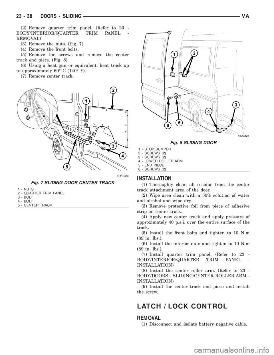
(3) Remove the nuts. (Fig. 7)
(4) Remove the front bolts.
(5) Remove the screws and remove the center
track end piece. (Fig. 8)
(6) Using a heat gun or equivalent, heat track up
to approximately 60É C (140É F).
(7) Remove center track.
INSTALLATION
(1) Thoroughly clean all residue from the center
track attachment area of the door.
(2) Wipe area clean with a 50% solution of water
and alcohol and wipe dry.
(3) Remove protective foil from piece of adhesive
strip on center track.
(4) Apply new center track and apply pressure of
approximately 40 p.s.i. over the entire surface of the
track.
(5) Install the front bolts and tighten to 10 N´m
(89 in. lbs.).
(6) Install the interior nuts and tighten to 10 N´m
(89 in. lbs.).
(7) Install quarter trim panel. (Refer to 23 -
BODY/INTERIOR/QUARTER TRIM PANEL -
INSTALLATION)
(8) Install the center roller arm. (Refer to 23 -
BODY/DOORS - SLIDING/CENTER ROLLER ARM -
INSTALLATION)
(9) Install the center track end piece and install
the screw.
LATCH / LOCK CONTROL
REMOVAL
(1) Disconnect and isolate battery negative cable.
Fig. 7 SLIDING DOOR CENTER TRACK
1 - NUTS
2 - QUARTER TRIM PANEL
3 - BOLT
4 - BOLT
5 - CENTER TRACK
Fig. 8 SLIDING DOOR
1 - STOP BUMPER
2 - SCREWS (2)
3 - SCREWS (2)
4 - LOWER ROLLER ARM
5 - END PIECE
6 - SCREWS (2)
23 - 38 DOORS - SLIDINGVA