2006 MERCEDES-BENZ SPRINTER check engine
[x] Cancel search: check enginePage 97 of 2305
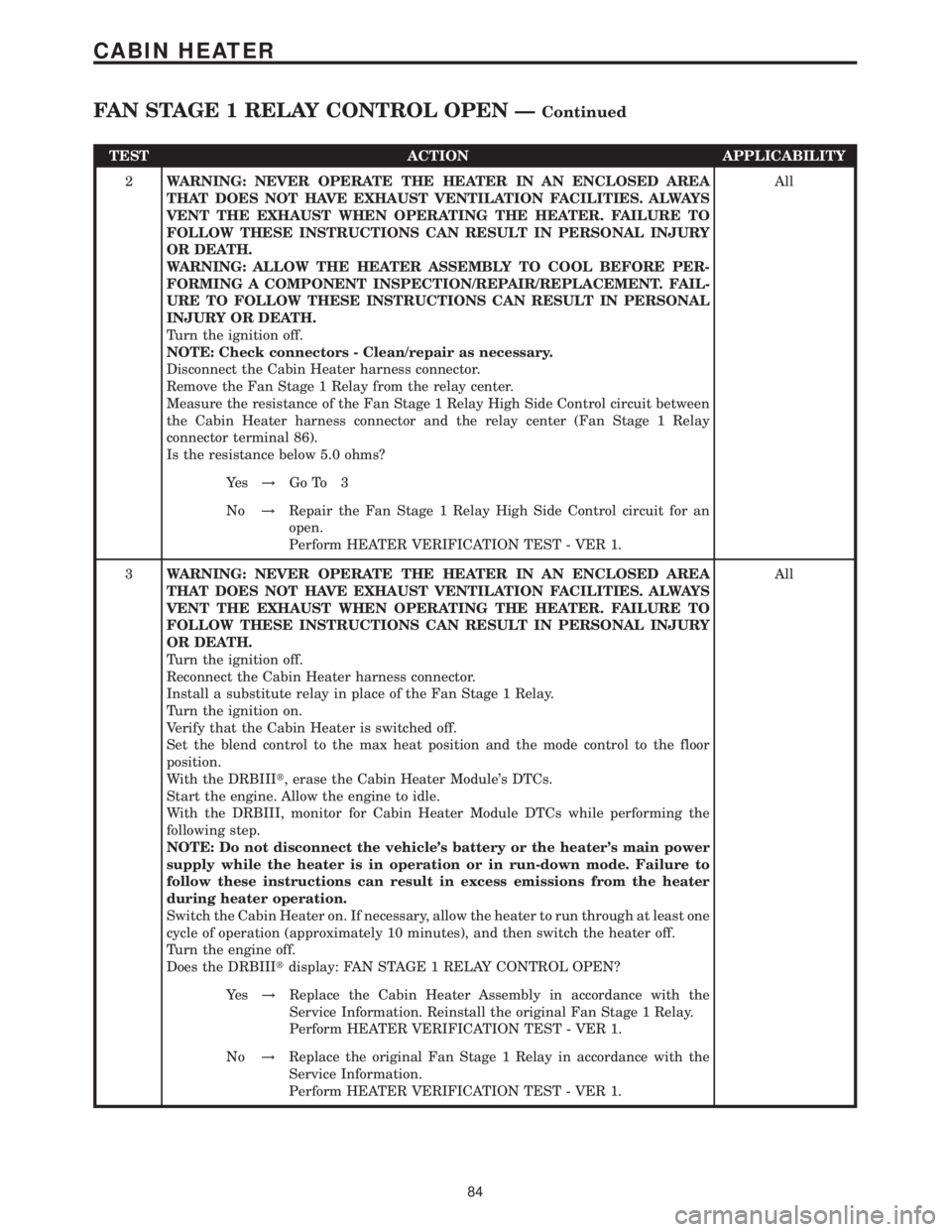
TEST ACTION APPLICABILITY
2WARNING: NEVER OPERATE THE HEATER IN AN ENCLOSED AREA
THAT DOES NOT HAVE EXHAUST VENTILATION FACILITIES. ALWAYS
VENT THE EXHAUST WHEN OPERATING THE HEATER. FAILURE TO
FOLLOW THESE INSTRUCTIONS CAN RESULT IN PERSONAL INJURY
OR DEATH.
WARNING: ALLOW THE HEATER ASSEMBLY TO COOL BEFORE PER-
FORMING A COMPONENT INSPECTION/REPAIR/REPLACEMENT. FAIL-
URE TO FOLLOW THESE INSTRUCTIONS CAN RESULT IN PERSONAL
INJURY OR DEATH.
Turn the ignition off.
NOTE: Check connectors - Clean/repair as necessary.
Disconnect the Cabin Heater harness connector.
Remove the Fan Stage 1 Relay from the relay center.
Measure the resistance of the Fan Stage 1 Relay High Side Control circuit between
the Cabin Heater harness connector and the relay center (Fan Stage 1 Relay
connector terminal 86).
Is the resistance below 5.0 ohms?All
Ye s!Go To 3
No!Repair the Fan Stage 1 Relay High Side Control circuit for an
open.
Perform HEATER VERIFICATION TEST - VER 1.
3WARNING: NEVER OPERATE THE HEATER IN AN ENCLOSED AREA
THAT DOES NOT HAVE EXHAUST VENTILATION FACILITIES. ALWAYS
VENT THE EXHAUST WHEN OPERATING THE HEATER. FAILURE TO
FOLLOW THESE INSTRUCTIONS CAN RESULT IN PERSONAL INJURY
OR DEATH.
Turn the ignition off.
Reconnect the Cabin Heater harness connector.
Install a substitute relay in place of the Fan Stage 1 Relay.
Turn the ignition on.
Verify that the Cabin Heater is switched off.
Set the blend control to the max heat position and the mode control to the floor
position.
With the DRBIIIt, erase the Cabin Heater Module's DTCs.
Start the engine. Allow the engine to idle.
With the DRBIII, monitor for Cabin Heater Module DTCs while performing the
following step.
NOTE: Do not disconnect the vehicle's battery or the heater's main power
supply while the heater is in operation or in run-down mode. Failure to
follow these instructions can result in excess emissions from the heater
during heater operation.
Switch the Cabin Heater on. If necessary, allow the heater to run through at least one
cycle of operation (approximately 10 minutes), and then switch the heater off.
Turn the engine off.
Does the DRBIIItdisplay: FAN STAGE 1 RELAY CONTROL OPEN?All
Ye s!Replace the Cabin Heater Assembly in accordance with the
Service Information. Reinstall the original Fan Stage 1 Relay.
Perform HEATER VERIFICATION TEST - VER 1.
No!Replace the original Fan Stage 1 Relay in accordance with the
Service Information.
Perform HEATER VERIFICATION TEST - VER 1.
84
CABIN HEATER
FAN STAGE 1 RELAY CONTROL OPEN ÐContinued
Page 107 of 2305
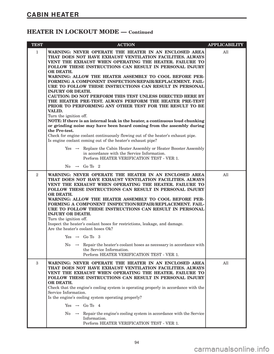
TEST ACTION APPLICABILITY
1WARNING: NEVER OPERATE THE HEATER IN AN ENCLOSED AREA
THAT DOES NOT HAVE EXHAUST VENTILATION FACILITIES. ALWAYS
VENT THE EXHAUST WHEN OPERATING THE HEATER. FAILURE TO
FOLLOW THESE INSTRUCTIONS CAN RESULT IN PERSONAL INJURY
OR DEATH.
WARNING: ALLOW THE HEATER ASSEMBLY TO COOL BEFORE PER-
FORMING A COMPONENT INSPECTION/REPAIR/REPLACEMENT. FAIL-
URE TO FOLLOW THESE INSTRUCTIONS CAN RESULT IN PERSONAL
INJURY OR DEATH.
CAUTION: DO NOT PERFORM THIS TEST UNLESS DIRECTED HERE BY
THE HEATER PRE-TEST. ALWAYS PERFORM THE HEATER PRE-TEST
PRIOR TO PERFORMING ANY OTHER TEST FOR THE RESULT TO BE
VALID.
Turn the ignition off.
NOTE: If there is an internal leak in the heater, a continuous loud chunking
or grinding noise may have been heard coming from the assembly during
the Pre-test.
Check for engine coolant continuously flowing out of the heater's exhaust pipe.
Is engine coolant coming out of the heater's exhaust pipe?All
Ye s!Replace the Cabin Heater Assembly or Heater Booster Assembly
in accordance with the Service Information.
Perform HEATER VERIFICATION TEST - VER 1.
No!Go To 2
2WARNING: NEVER OPERATE THE HEATER IN AN ENCLOSED AREA
THAT DOES NOT HAVE EXHAUST VENTILATION FACILITIES. ALWAYS
VENT THE EXHAUST WHEN OPERATING THE HEATER. FAILURE TO
FOLLOW THESE INSTRUCTIONS CAN RESULT IN PERSONAL INJURY
OR DEATH.
WARNING: ALLOW THE HEATER ASSEMBLY TO COOL BEFORE PER-
FORMING A COMPONENT INSPECTION/REPAIR/REPLACEMENT. FAIL-
URE TO FOLLOW THESE INSTRUCTIONS CAN RESULT IN PERSONAL
INJURY OR DEATH.
Turn the ignition off.
Inspect the heater's coolant hoses for restrictions, leakage, and damage.
Are the heater's coolant hoses Ok?All
Ye s!Go To 3
No!Repair the heater's coolant hoses as necessary in accordance with
the Service Information.
Perform HEATER VERIFICATION TEST - VER 1.
3WARNING: NEVER OPERATE THE HEATER IN AN ENCLOSED AREA
THAT DOES NOT HAVE EXHAUST VENTILATION FACILITIES. ALWAYS
VENT THE EXHAUST WHEN OPERATING THE HEATER. FAILURE TO
FOLLOW THESE INSTRUCTIONS CAN RESULT IN PERSONAL INJURY
OR DEATH.
Check that the engine's cooling system is operating properly in accordance with the
Service Information.
Is the engine's cooling system operating properly?All
Ye s!Go To 4
No!Repair the engine's cooling system in accordance with the Service
Information.
Perform HEATER VERIFICATION TEST - VER 1.
94
CABIN HEATER
HEATER IN LOCKOUT MODE ÐContinued
Page 109 of 2305
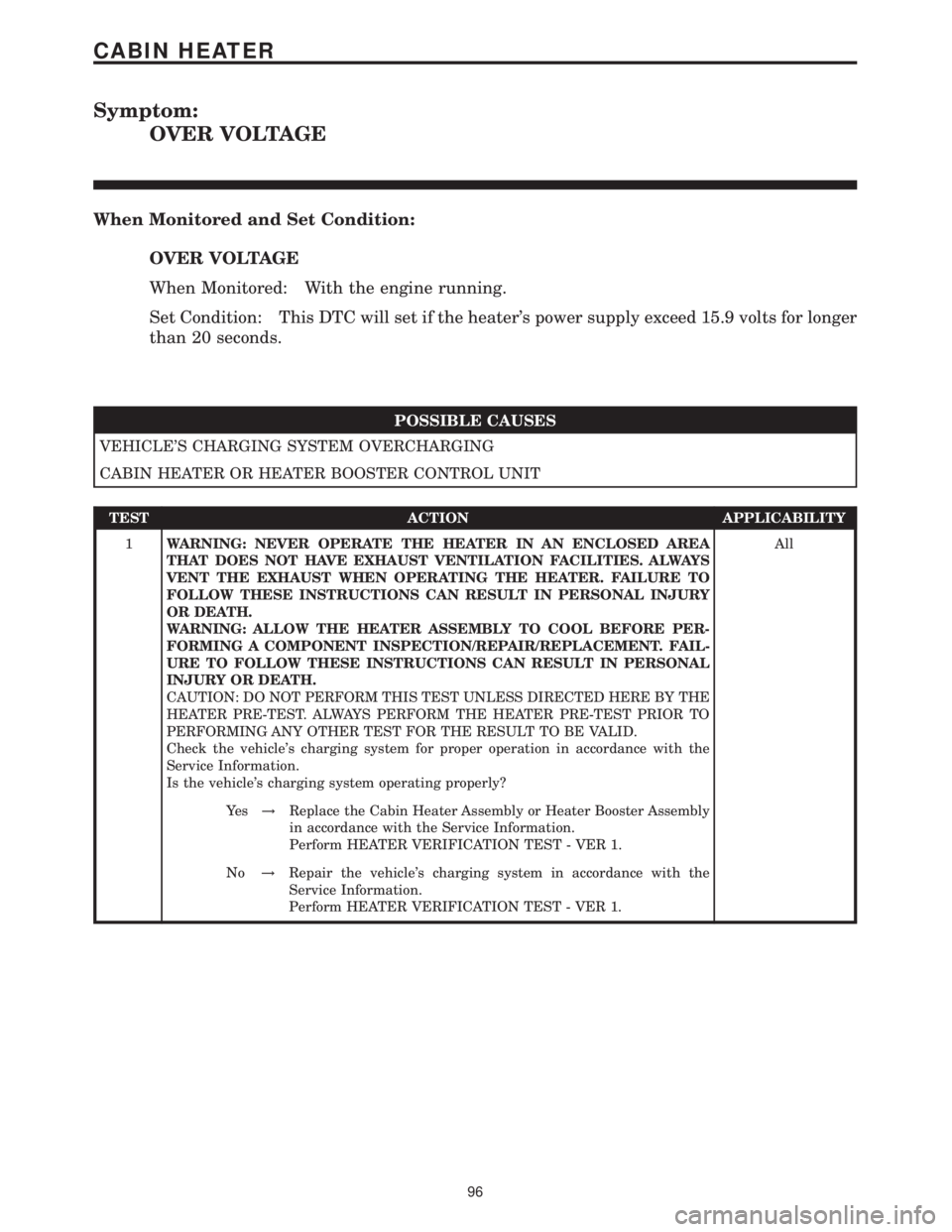
Symptom:
OVER VOLTAGE
When Monitored and Set Condition:
OVER VOLTAGE
When Monitored: With the engine running.
Set Condition: This DTC will set if the heater's power supply exceed 15.9 volts for longer
than 20 seconds.
POSSIBLE CAUSES
VEHICLE'S CHARGING SYSTEM OVERCHARGING
CABIN HEATER OR HEATER BOOSTER CONTROL UNIT
TEST ACTION APPLICABILITY
1WARNING: NEVER OPERATE THE HEATER IN AN ENCLOSED AREA
THAT DOES NOT HAVE EXHAUST VENTILATION FACILITIES. ALWAYS
VENT THE EXHAUST WHEN OPERATING THE HEATER. FAILURE TO
FOLLOW THESE INSTRUCTIONS CAN RESULT IN PERSONAL INJURY
OR DEATH.
WARNING: ALLOW THE HEATER ASSEMBLY TO COOL BEFORE PER-
FORMING A COMPONENT INSPECTION/REPAIR/REPLACEMENT. FAIL-
URE TO FOLLOW THESE INSTRUCTIONS CAN RESULT IN PERSONAL
INJURY OR DEATH.
CAUTION: DO NOT PERFORM THIS TEST UNLESS DIRECTED HERE BY THE
HEATER PRE-TEST. ALWAYS PERFORM THE HEATER PRE-TEST PRIOR TO
PERFORMING ANY OTHER TEST FOR THE RESULT TO BE VALID.
Check the vehicle's charging system for proper operation in accordance with the
Service Information.
Is the vehicle's charging system operating properly?All
Ye s!Replace the Cabin Heater Assembly or Heater Booster Assembly
in accordance with the Service Information.
Perform HEATER VERIFICATION TEST - VER 1.
No!Repair the vehicle's charging system in accordance with the
Service Information.
Perform HEATER VERIFICATION TEST - VER 1.
96
CABIN HEATER
Page 112 of 2305
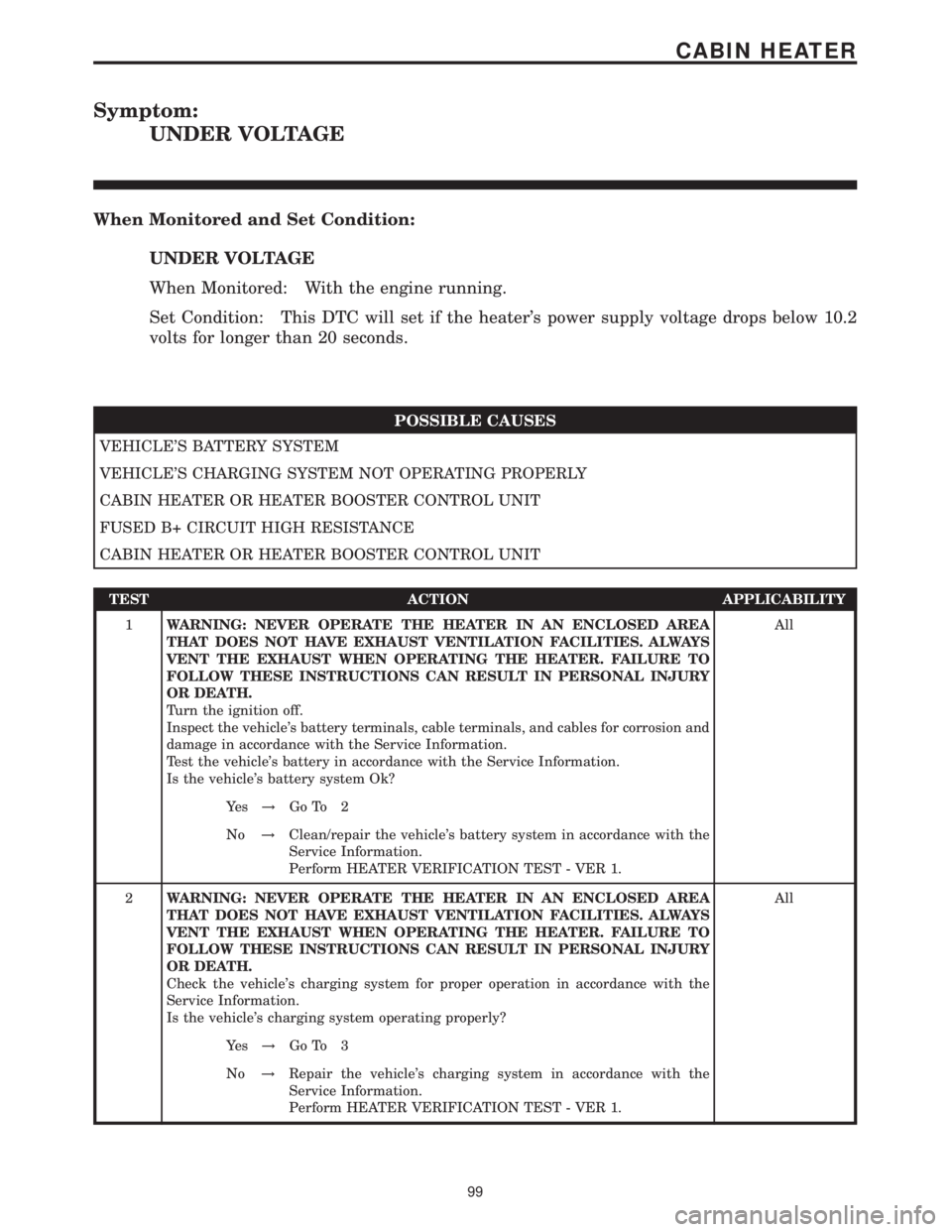
Symptom:
UNDER VOLTAGE
When Monitored and Set Condition:
UNDER VOLTAGE
When Monitored: With the engine running.
Set Condition: This DTC will set if the heater's power supply voltage drops below 10.2
volts for longer than 20 seconds.
POSSIBLE CAUSES
VEHICLE'S BATTERY SYSTEM
VEHICLE'S CHARGING SYSTEM NOT OPERATING PROPERLY
CABIN HEATER OR HEATER BOOSTER CONTROL UNIT
FUSED B+ CIRCUIT HIGH RESISTANCE
CABIN HEATER OR HEATER BOOSTER CONTROL UNIT
TEST ACTION APPLICABILITY
1WARNING: NEVER OPERATE THE HEATER IN AN ENCLOSED AREA
THAT DOES NOT HAVE EXHAUST VENTILATION FACILITIES. ALWAYS
VENT THE EXHAUST WHEN OPERATING THE HEATER. FAILURE TO
FOLLOW THESE INSTRUCTIONS CAN RESULT IN PERSONAL INJURY
OR DEATH.
Turn the ignition off.
Inspect the vehicle's battery terminals, cable terminals, and cables for corrosion and
damage in accordance with the Service Information.
Test the vehicle's battery in accordance with the Service Information.
Is the vehicle's battery system Ok?All
Ye s!Go To 2
No!Clean/repair the vehicle's battery system in accordance with the
Service Information.
Perform HEATER VERIFICATION TEST - VER 1.
2WARNING: NEVER OPERATE THE HEATER IN AN ENCLOSED AREA
THAT DOES NOT HAVE EXHAUST VENTILATION FACILITIES. ALWAYS
VENT THE EXHAUST WHEN OPERATING THE HEATER. FAILURE TO
FOLLOW THESE INSTRUCTIONS CAN RESULT IN PERSONAL INJURY
OR DEATH.
Check the vehicle's charging system for proper operation in accordance with the
Service Information.
Is the vehicle's charging system operating properly?All
Ye s!Go To 3
No!Repair the vehicle's charging system in accordance with the
Service Information.
Perform HEATER VERIFICATION TEST - VER 1.
99
CABIN HEATER
Page 125 of 2305

Symptom:
*NO RESPONSE FROM ENGINE CONTROL MODULE
POSSIBLE CAUSES
CHECK POWERS AND GROUNDS TO THE ENGINE CONTROL MODULE
K-ECM CIRCUIT SHORTED TO GROUND
K-ECM CIRCUIT SHORTED TO VOLTAGE
K-ECM CIRCUIT OPEN
ENGINE CONTROL MODULE
TEST ACTION APPLICABILITY
1 Turn the ignition off.
Disconnect the Engine Control Module harness connectors.
Check each power and ground circuit to the module.
Were any problems found?All
Ye s!Refer to the wiring diagrams located in the service information to
help isolate an open or shorted condition. Repair as necessary.
Perform ROAD TEST VERIFICATION - VER-2.
No!Go To 2
2 Turn the ignition off.
Disconnect the ECM harness connectors.
Disconnect the DRBIIItfrom the DLC.
Measure the resistance between ground and the K-ECM circuit.
Is the resistance below 5.0 ohms?All
Ye s!Repair the K-ECM circuit for a short to ground.
Perform ROAD TEST VERIFICATION - VER-2.
No!Go To 3
3 Turn the ignition off.
Disconnect the DRBIIItfrom the DLC.
Disconnect the ECM harness connectors.
Turn the ignition on.
Using a 12-volt test light connected to ground, probe the K-ECM circuit.
NOTE: The test light must illuminate brightly. Compare the brightness to
that of a direct connection to the battery.
Does the test light illuminate brightly?All
Ye s!Repair the K-ECM circuit for a short to voltage.
Perform ROAD TEST VERIFICATION - VER-2.
No!Go To 4
11 2
COMMUNICATION
Page 144 of 2305
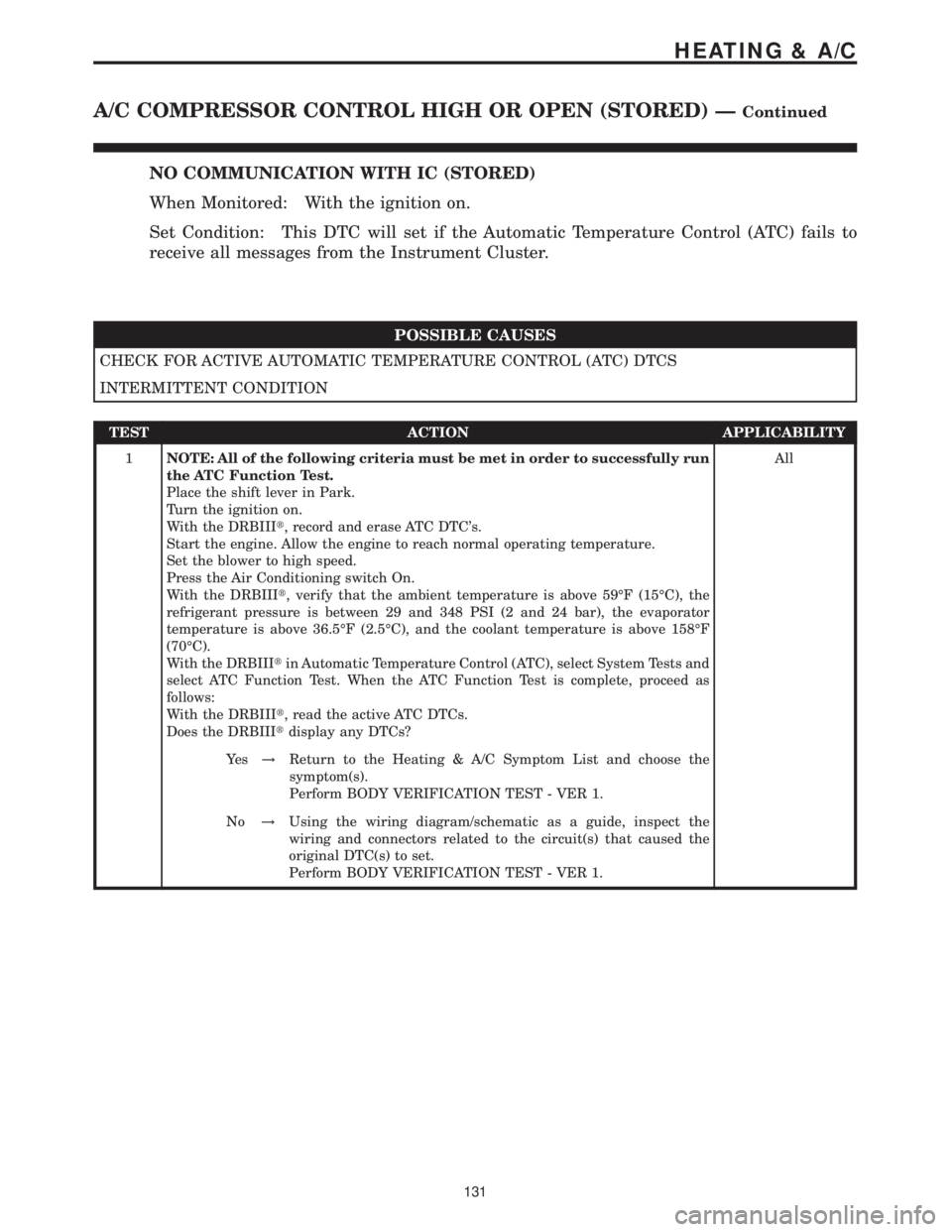
NO COMMUNICATION WITH IC (STORED)
When Monitored: With the ignition on.
Set Condition: This DTC will set if the Automatic Temperature Control (ATC) fails to
receive all messages from the Instrument Cluster.
POSSIBLE CAUSES
CHECK FOR ACTIVE AUTOMATIC TEMPERATURE CONTROL (ATC) DTCS
INTERMITTENT CONDITION
TEST ACTION APPLICABILITY
1NOTE: All of the following criteria must be met in order to successfully run
the ATC Function Test.
Place the shift lever in Park.
Turn the ignition on.
With the DRBIIIt, record and erase ATC DTC's.
Start the engine. Allow the engine to reach normal operating temperature.
Set the blower to high speed.
Press the Air Conditioning switch On.
With the DRBIIIt, verify that the ambient temperature is above 59ÉF (15ÉC), the
refrigerant pressure is between 29 and 348 PSI (2 and 24 bar), the evaporator
temperature is above 36.5ÉF (2.5ÉC), and the coolant temperature is above 158ÉF
(70ÉC).
With the DRBIIItin Automatic Temperature Control (ATC), select System Tests and
select ATC Function Test. When the ATC Function Test is complete, proceed as
follows:
With the DRBIIIt, read the active ATC DTCs.
Does the DRBIIItdisplay any DTCs?All
Ye s!Return to the Heating & A/C Symptom List and choose the
symptom(s).
Perform BODY VERIFICATION TEST - VER 1.
No!Using the wiring diagram/schematic as a guide, inspect the
wiring and connectors related to the circuit(s) that caused the
original DTC(s) to set.
Perform BODY VERIFICATION TEST - VER 1.
131
HEATING & A/C
A/C COMPRESSOR CONTROL HIGH OR OPEN (STORED) ÐContinued
Page 165 of 2305

Symptom:
CIRC PUMP CONTROL HIGH OR OPEN (ACTIVE)
POSSIBLE CAUSES
CIRCULATION PUMP
CIRCULATION PUMP CONTROL CIRCUIT SHORTED TO VOLTAGE
AUTOMATIC TEMPERATURE CONTROL (ATC)
CIRCULATION PUMP CONTROL CIRCUIT OPEN
GROUND CIRCUIT OPEN
AUTOMATIC TEMPERATURE CONTROL (ATC)
TEST ACTION APPLICABILITY
1 Turn the ignition off.
Press the Residual Engine Heat Utilization (REST) switch off.
NOTE: Check connectors - Clean/repair as necessary.
Disconnect the Circulation Pump harness connector.
Connect a 12-volt test light between the Circulation Pump Control circuit and the
Ground circuit in the Circulation Pump harness connector. The test light should
operate as follows:
With the Residual Engine Heat Utilization (REST) switch off, the test light should
not illuminate.
Press the Residual Engine Heat Utilization (REST) switch on. The test light should
illuminate brightly.
Does the test light function as specified?All
Yes, Light Only Illuminates With REST On
Replace the Circulation Pump in accordance with the Service
Information.
Perform BODY VERIFICATION TEST - VER 1.
No, Light Illuminates With REST Off
Go To 2
No, Light Will Not Illuminate
Go To 3
2 Turn the ignition off.
NOTE: Check connectors - Clean/repair as necessary.
Disconnect the Circulation Pump harness connector.
Disconnect the Automatic Temperature Control (ATC) C1 harness connector.
Turn the ignition on.
Measure the voltage of the Circulation Pump Control circuit.
Is the voltage above 0.2 volts?All
Ye s!Repair the Circulation Pump Control circuit for a short to voltage.
Perform BODY VERIFICATION TEST - VER 1.
No!Replace the Automatic Temperature Control (ATC) in accordance
with the Service Information.
Perform BODY VERIFICATION TEST - VER 1.
152
HEATING & A/C
Page 176 of 2305
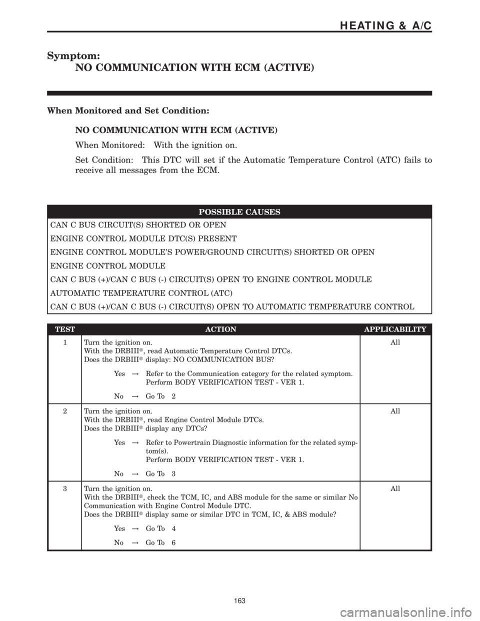
Symptom:
NO COMMUNICATION WITH ECM (ACTIVE)
When Monitored and Set Condition:
NO COMMUNICATION WITH ECM (ACTIVE)
When Monitored: With the ignition on.
Set Condition: This DTC will set if the Automatic Temperature Control (ATC) fails to
receive all messages from the ECM.
POSSIBLE CAUSES
CAN C BUS CIRCUIT(S) SHORTED OR OPEN
ENGINE CONTROL MODULE DTC(S) PRESENT
ENGINE CONTROL MODULE'S POWER/GROUND CIRCUIT(S) SHORTED OR OPEN
ENGINE CONTROL MODULE
CAN C BUS (+)/CAN C BUS (-) CIRCUIT(S) OPEN TO ENGINE CONTROL MODULE
AUTOMATIC TEMPERATURE CONTROL (ATC)
CAN C BUS (+)/CAN C BUS (-) CIRCUIT(S) OPEN TO AUTOMATIC TEMPERATURE CONTROL
TEST ACTION APPLICABILITY
1 Turn the ignition on.
With the DRBIIIt, read Automatic Temperature Control DTCs.
Does the DRBIIItdisplay: NO COMMUNICATION BUS?All
Ye s!Refer to the Communication category for the related symptom.
Perform BODY VERIFICATION TEST - VER 1.
No!Go To 2
2 Turn the ignition on.
With the DRBIIIt, read Engine Control Module DTCs.
Does the DRBIIItdisplay any DTCs?All
Ye s!Refer to Powertrain Diagnostic information for the related symp-
tom(s).
Perform BODY VERIFICATION TEST - VER 1.
No!Go To 3
3 Turn the ignition on.
With the DRBIIIt, check the TCM, IC, and ABS module for the same or similar No
Communication with Engine Control Module DTC.
Does the DRBIIItdisplay same or similar DTC in TCM, IC, & ABS module?All
Ye s!Go To 4
No!Go To 6
163
HEATING & A/C