2006 MERCEDES-BENZ SPRINTER heater
[x] Cancel search: heaterPage 1581 of 2305
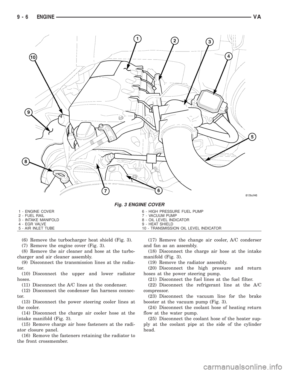
(6) Remove the turbocharger heat shield (Fig. 3).
(7) Remove the engine cover (Fig. 3).
(8) Remove the air cleaner and hose at the turbo-
charger and air cleaner assembly.
(9) Disconnect the transmission lines at the radia-
tor.
(10) Disconnect the upper and lower radiator
hoses.
(11) Disconnect the A/C lines at the condenser.
(12) Disconnect the condenser fan harness connec-
tor.
(13) Disconnect the power steering cooler lines at
the cooler.
(14) Disconnect the charge air cooler hose at the
intake manifold (Fig. 3).
(15) Remove charge air hose fasteners at the radi-
ator closure panel.
(16) Remove the fasteners retaining the radiator to
the front crossmember.(17) Remove the change air cooler, A/C conderser
and fan as an assembly.
(18) Disconnect the charge air hose at the intake
manifold (Fig. 3).
(19) Remove the radiator assembly.
(20) Disconnect the high pressure and return
hoses at the power steering pump.
(21) Disconnect the fuel lines at the fuel filter.
(22) Disconnect the refrigerant line at the A/C
compressor.
(23) Disconnect the vacuum line for the brake
booster at the vacuum pump (Fig. 3).
(24) Disconnect the coolant hose of heating return
flow at the water pump.
(25) Disconnect the coolant hose of the heater sup-
ply at the coolant pipe at the side of the cylinder
head.
Fig. 3 ENGINE COVER
1 - ENGINE COVER 6 - HIGH PRESSURE FUEL PUMP
2 - FUEL RAIL 7 - VACUUM PUMP
3 - INTAKE MANIFOLD 8 - OIL LEVEL INDICATOR
4 - EGR VALVE 9 - HEAT SHIELD
5 - AIR INLET TUBE 10 - TRANSMISSION OIL LEVEL INDICATOR
9 - 6 ENGINEVA
Page 1582 of 2305
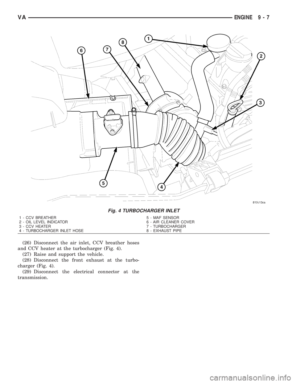
(26) Disconnect the air inlet, CCV breather hoses
and CCV heater at the turbocharger (Fig. 4).
(27) Raise and support the vehicle.
(28) Disconnect the front exhaust at the turbo-
charger (Fig. 4).
(29) Disconnect the electrical connector at the
transmission.
Fig. 4 TURBOCHARGER INLET
1 - CCV BREATHER 5 - MAF SENSOR
2 - OIL LEVEL INDICATOR 6 - AIR CLEANER COVER
3 - CCV HEATER 7 - TURBOCHARGER
4 - TURBOCHARGER INLET HOSE 8 - EXHAUST PIPE
VAENGINE 9 - 7
Page 1583 of 2305
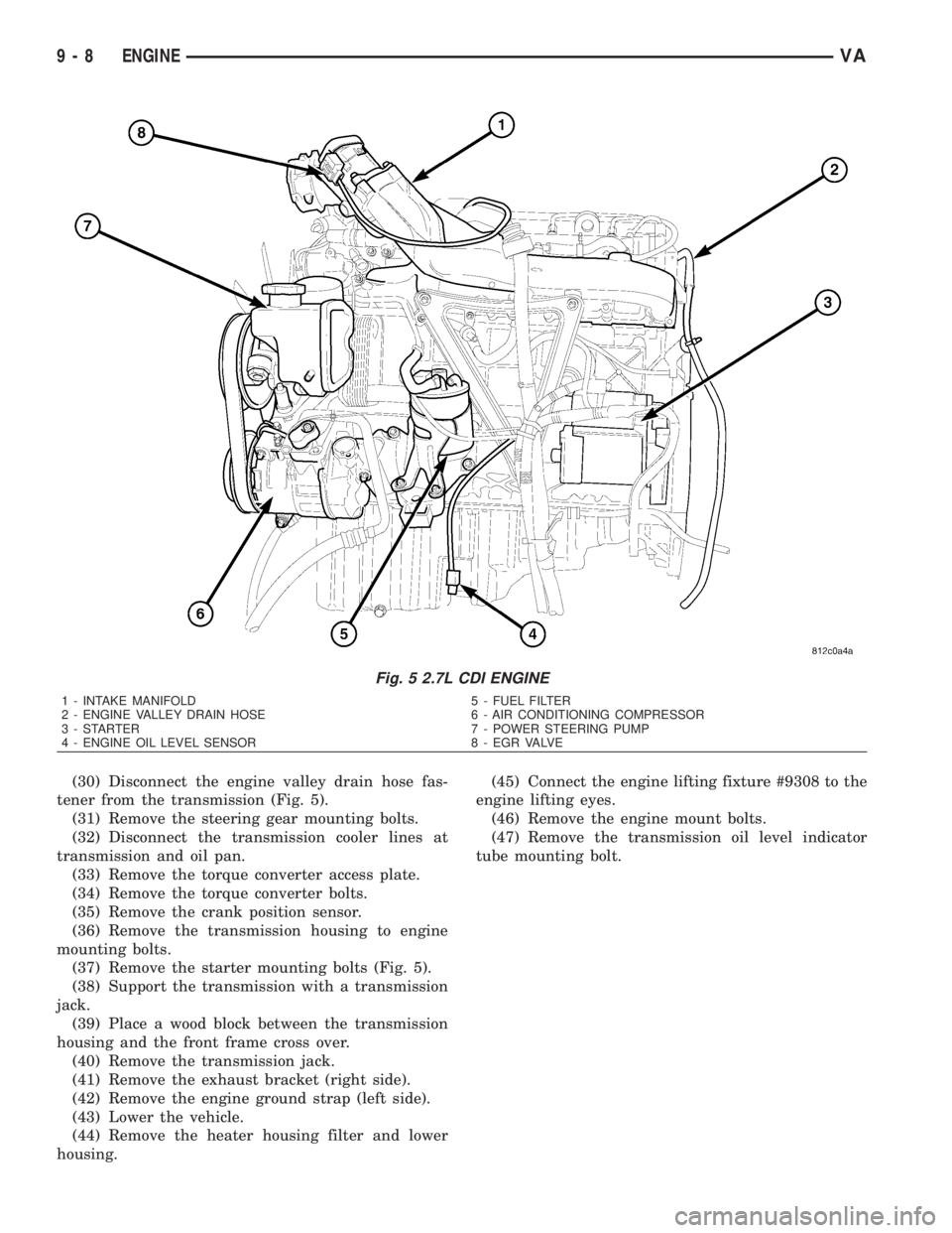
(30) Disconnect the engine valley drain hose fas-
tener from the transmission (Fig. 5).
(31) Remove the steering gear mounting bolts.
(32) Disconnect the transmission cooler lines at
transmission and oil pan.
(33) Remove the torque converter access plate.
(34) Remove the torque converter bolts.
(35) Remove the crank position sensor.
(36) Remove the transmission housing to engine
mounting bolts.
(37) Remove the starter mounting bolts (Fig. 5).
(38) Support the transmission with a transmission
jack.
(39) Place a wood block between the transmission
housing and the front frame cross over.
(40) Remove the transmission jack.
(41) Remove the exhaust bracket (right side).
(42) Remove the engine ground strap (left side).
(43) Lower the vehicle.
(44) Remove the heater housing filter and lower
housing.(45) Connect the engine lifting fixture #9308 to the
engine lifting eyes.
(46) Remove the engine mount bolts.
(47) Remove the transmission oil level indicator
tube mounting bolt.
Fig. 5 2.7L CDI ENGINE
1 - INTAKE MANIFOLD 5 - FUEL FILTER
2 - ENGINE VALLEY DRAIN HOSE 6 - AIR CONDITIONING COMPRESSOR
3 - STARTER 7 - POWER STEERING PUMP
4 - ENGINE OIL LEVEL SENSOR 8 - EGR VALVE
9 - 8 ENGINEVA
Page 1585 of 2305
(11) Install the torque converter access plate. Refer
to (Refer to 21 - TRANSMISSION/TRANSAXLE/AU-
TOMATIC - NAG1 - INSTALLATION) for correct
sequence and torque specification.
(12) Install the transmission cooler lines to trans-
mission. (Refer to 21 - TRANSMISSION/TRANS-
AXLE/AUTOMATIC - NAG1 - INSTALLATION) for
correct sequence and torque specification.
(13) Connect the engine valley drain hose to the
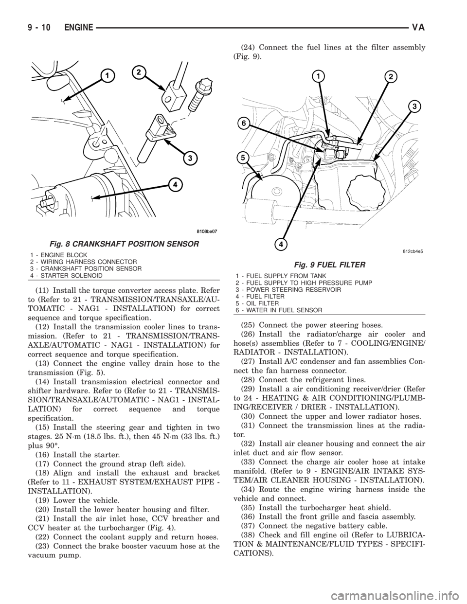
transmission (Fig. 5).
(14) Install transmission electrical connector and
shifter hardware. Refer to (Refer to 21 - TRANSMIS-
SION/TRANSAXLE/AUTOMATIC - NAG1 - INSTAL-
LATION) for correct sequence and torque
specification.
(15) Install the steering gear and tighten in two
stages. 25 N´m (18.5 lbs. ft.), then 45 N´m (33 lbs. ft.)
plus 90É.
(16) Install the starter.
(17) Connect the ground strap (left side).
(18) Align and install the exhaust and bracket
(Refer to 11 - EXHAUST SYSTEM/EXHAUST PIPE -
INSTALLATION).
(19) Lower the vehicle.
(20) Install the lower heater housing and filter.
(21) Install the air inlet hose, CCV breather and
CCV heater at the turbocharger (Fig. 4).
(22) Connect the coolant supply and return hoses.
(23) Connect the brake booster vacuum hose at the
vacuum pump.(24) Connect the fuel lines at the filter assembly
(Fig. 9).
(25) Connect the power steering hoses.
(26) Install the radiator/charge air cooler and
hose(s) assemblies (Refer to 7 - COOLING/ENGINE/
RADIATOR - INSTALLATION).
(27) Install A/C condenser and fan assemblies Con-
nect the fan harness connector.
(28) Connect the refrigerant lines.
(29) Install a air conditioning receiver/drier (Refer
to 24 - HEATING & AIR CONDITIONING/PLUMB-
ING/RECEIVER / DRIER - INSTALLATION).
(30) Connect the upper and lower radiator hoses.
(31) Connect the transmission lines at the radia-
tor.
(32) Install air cleaner housing and connect the air
inlet duct and air flow sensor.
(33) Connect the charge air cooler hose at intake
manifold. (Refer to 9 - ENGINE/AIR INTAKE SYS-
TEM/AIR CLEANER HOUSING - INSTALLATION).
(34) Route the engine wiring harness inside the
vehicle and connect.
(35) Install the turbocharger heat shield.
(36) Install the front grille and fascia assembly.
(37) Connect the negative battery cable.
(38) Check and fill engine oil (Refer to LUBRICA-
TION & MAINTENANCE/FLUID TYPES - SPECIFI-
CATIONS).
Fig. 8 CRANKSHAFT POSITION SENSOR
1 - ENGINE BLOCK
2 - WIRING HARNESS CONNECTOR
3 - CRANKSHAFT POSITION SENSOR
4 - STARTER SOLENOID
Fig. 9 FUEL FILTER
1 - FUEL SUPPLY FROM TANK
2 - FUEL SUPPLY TO HIGH PRESSURE PUMP
3 - POWER STEERING RESERVOIR
4 - FUEL FILTER
5 - OIL FILTER
6 - WATER IN FUEL SENSOR
9 - 10 ENGINEVA
Page 1589 of 2305
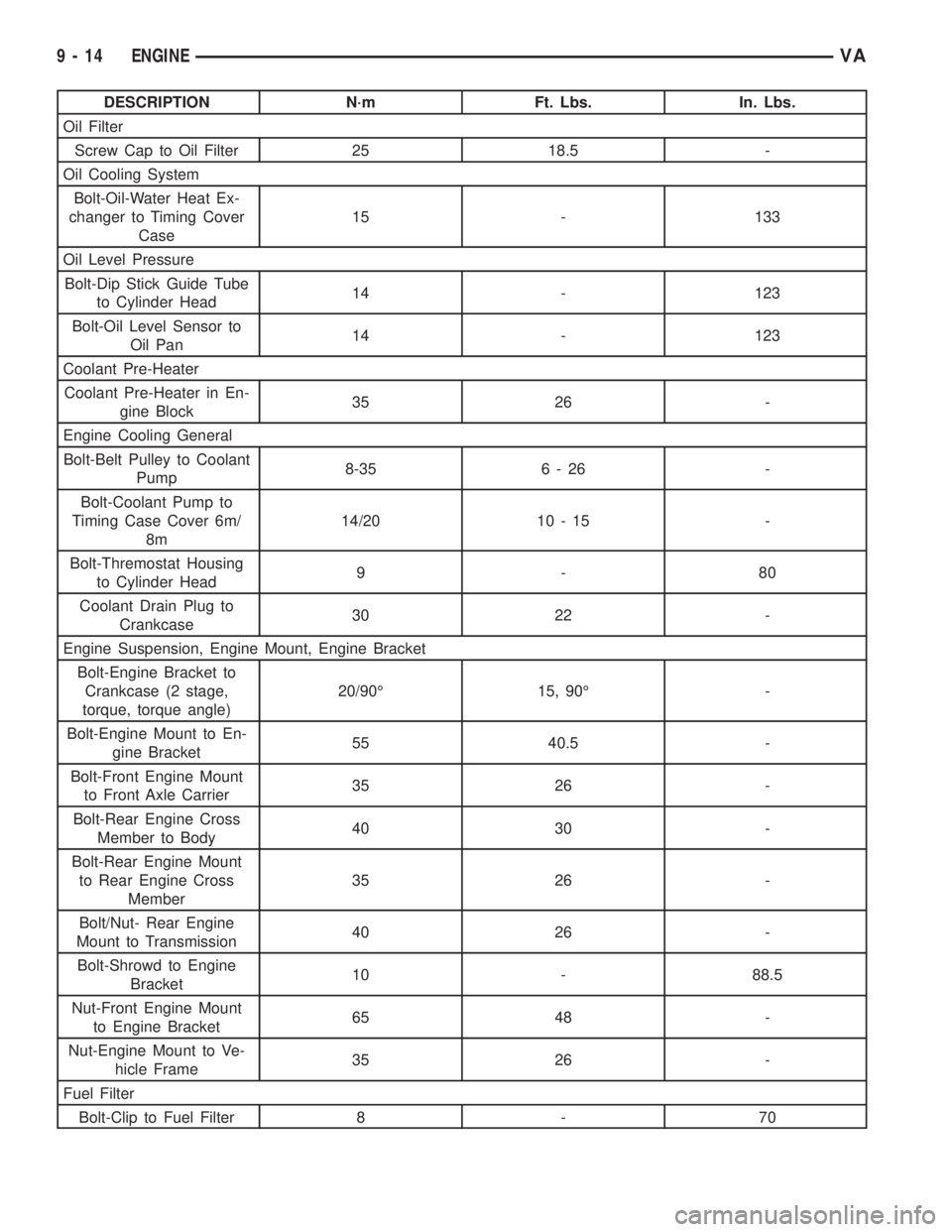
DESCRIPTION N´m Ft. Lbs. In. Lbs.
Oil Filter
Screw Cap to Oil Filter 25 18.5 -
Oil Cooling System
Bolt-Oil-Water Heat Ex-
changer to Timing Cover
Case15 - 133
Oil Level Pressure
Bolt-Dip Stick Guide Tube
to Cylinder Head14 - 123
Bolt-Oil Level Sensor to
Oil Pan14 - 123
Coolant Pre-Heater
Coolant Pre-Heater in En-
gine Block35 26 -
Engine Cooling General
Bolt-Belt Pulley to Coolant
Pump8-35 6 - 26 -
Bolt-Coolant Pump to
Timing Case Cover 6m/
8m14/20 10 - 15 -
Bolt-Thremostat Housing
to Cylinder Head9-80
Coolant Drain Plug to
Crankcase30 22 -
Engine Suspension, Engine Mount, Engine Bracket
Bolt-Engine Bracket to
Crankcase (2 stage,
torque, torque angle)20/90É 15, 90É -
Bolt-Engine Mount to En-
gine Bracket55 40.5 -
Bolt-Front Engine Mount
to Front Axle Carrier35 26 -
Bolt-Rear Engine Cross
Member to Body40 30 -
Bolt-Rear Engine Mount
to Rear Engine Cross
Member35 26 -
Bolt/Nut- Rear Engine
Mount to Transmission40 26 -
Bolt-Shrowd to Engine
Bracket10 - 88.5
Nut-Front Engine Mount
to Engine Bracket65 48 -
Nut-Engine Mount to Ve-
hicle Frame35 26 -
Fuel Filter
Bolt-Clip to Fuel Filter 8 - 70
9 - 14 ENGINEVA
Page 1591 of 2305
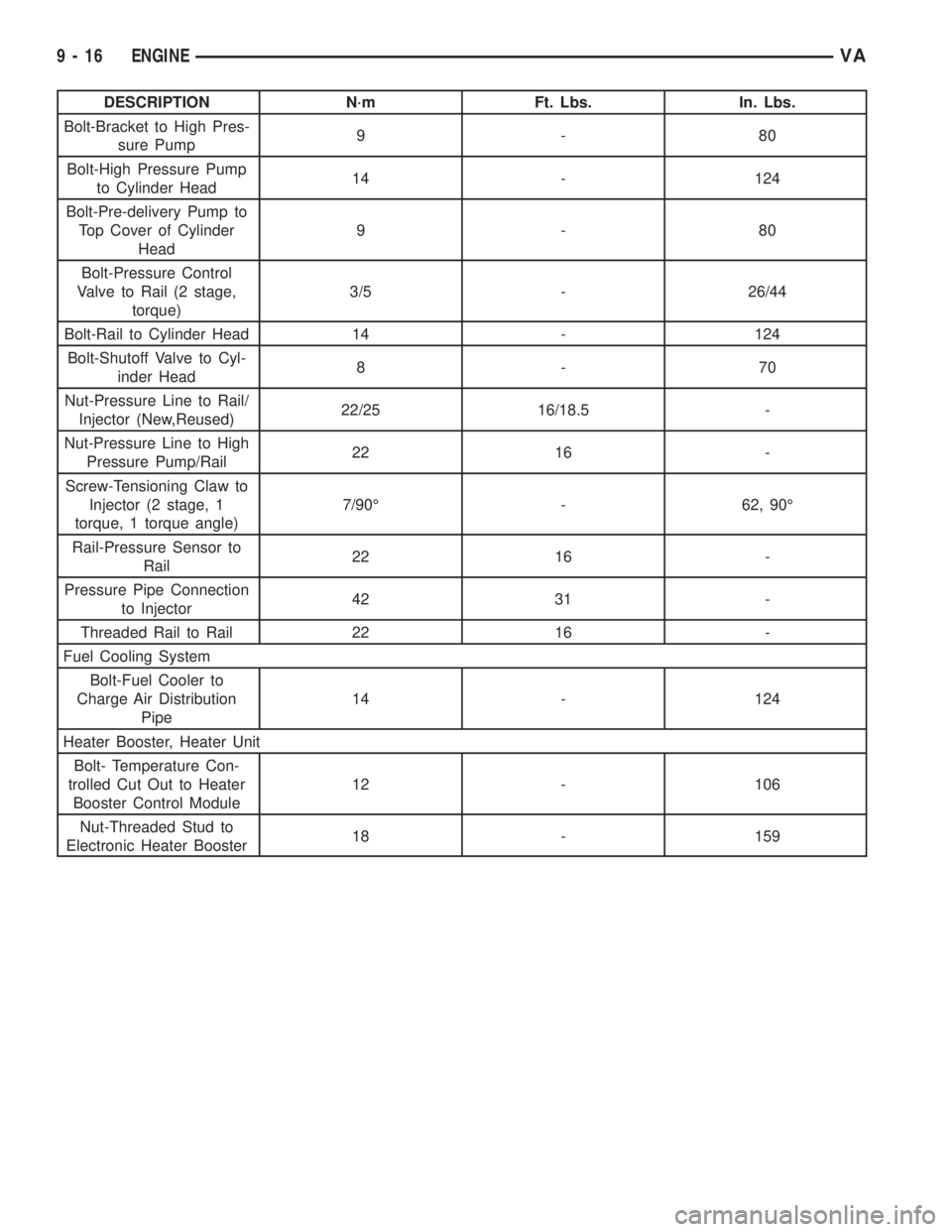
DESCRIPTION N´m Ft. Lbs. In. Lbs.
Bolt-Bracket to High Pres-
sure Pump9-80
Bolt-High Pressure Pump
to Cylinder Head14 - 124
Bolt-Pre-delivery Pump to
Top Cover of Cylinder
Head9-80
Bolt-Pressure Control
Valve to Rail (2 stage,
torque)3/5 - 26/44
Bolt-Rail to Cylinder Head 14 - 124
Bolt-Shutoff Valve to Cyl-
inder Head8-70
Nut-Pressure Line to Rail/
Injector (New,Reused)22/25 16/18.5 -
Nut-Pressure Line to High
Pressure Pump/Rail22 16 -
Screw-Tensioning Claw to
Injector (2 stage, 1
torque, 1 torque angle)7/90É - 62, 90É
Rail-Pressure Sensor to
Rail22 16 -
Pressure Pipe Connection
to Injector42 31 -
Threaded Rail to Rail 22 16 -
Fuel Cooling System
Bolt-Fuel Cooler to
Charge Air Distribution
Pipe14 - 124
Heater Booster, Heater Unit
Bolt- Temperature Con-
trolled Cut Out to Heater
Booster Control Module12 - 106
Nut-Threaded Stud to
Electronic Heater Booster18 - 159
9 - 16 ENGINEVA
Page 1629 of 2305
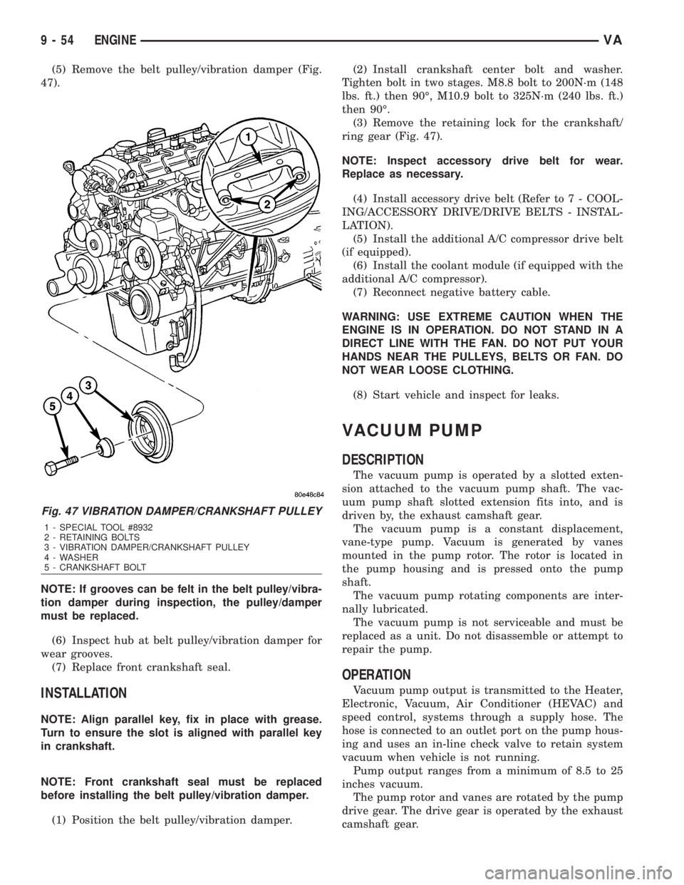
(5) Remove the belt pulley/vibration damper (Fig.
47).
NOTE: If grooves can be felt in the belt pulley/vibra-
tion damper during inspection, the pulley/damper
must be replaced.
(6) Inspect hub at belt pulley/vibration damper for
wear grooves.
(7) Replace front crankshaft seal.
INSTALLATION
NOTE: Align parallel key, fix in place with grease.
Turn to ensure the slot is aligned with parallel key
in crankshaft.
NOTE: Front crankshaft seal must be replaced
before installing the belt pulley/vibration damper.
(1) Position the belt pulley/vibration damper.(2) Install crankshaft center bolt and washer.
Tighten bolt in two stages. M8.8 bolt to 200N´m (148
lbs. ft.) then 90É, M10.9 bolt to 325N´m (240 lbs. ft.)
then 90É.
(3) Remove the retaining lock for the crankshaft/
ring gear (Fig. 47).
NOTE: Inspect accessory drive belt for wear.
Replace as necessary.
(4) Install accessory drive belt (Refer to 7 - COOL-
ING/ACCESSORY DRIVE/DRIVE BELTS - INSTAL-
LATION).
(5) Install the additional A/C compressor drive belt
(if equipped).
(6) Install the coolant module (if equipped with the
additional A/C compressor).
(7) Reconnect negative battery cable.
WARNING: USE EXTREME CAUTION WHEN THE
ENGINE IS IN OPERATION. DO NOT STAND IN A
DIRECT LINE WITH THE FAN. DO NOT PUT YOUR
HANDS NEAR THE PULLEYS, BELTS OR FAN. DO
NOT WEAR LOOSE CLOTHING.
(8) Start vehicle and inspect for leaks.
VACUUM PUMP
DESCRIPTION
The vacuum pump is operated by a slotted exten-
sion attached to the vacuum pump shaft. The vac-
uum pump shaft slotted extension fits into, and is
driven by, the exhaust camshaft gear.
The vacuum pump is a constant displacement,
vane-type pump. Vacuum is generated by vanes
mounted in the pump rotor. The rotor is located in
the pump housing and is pressed onto the pump
shaft.
The vacuum pump rotating components are inter-
nally lubricated.
The vacuum pump is not serviceable and must be
replaced as a unit. Do not disassemble or attempt to
repair the pump.
OPERATION
Vacuum pump output is transmitted to the Heater,
Electronic, Vacuum, Air Conditioner (HEVAC) and
speed control, systems through a supply hose. The
hose is connected to an outlet port on the pump hous-
ing and uses an in-line check valve to retain system
vacuum when vehicle is not running.
Pump output ranges from a minimum of 8.5 to 25
inches vacuum.
The pump rotor and vanes are rotated by the pump
drive gear. The drive gear is operated by the exhaust
camshaft gear.
Fig. 47 VIBRATION DAMPER/CRANKSHAFT PULLEY
1 - SPECIAL TOOL #8932
2 - RETAINING BOLTS
3 - VIBRATION DAMPER/CRANKSHAFT PULLEY
4 - WASHER
5 - CRANKSHAFT BOLT
9 - 54 ENGINEVA
Page 1644 of 2305
(8) Position the front exhaust pipe aside.
(9) Lower the vehicle.
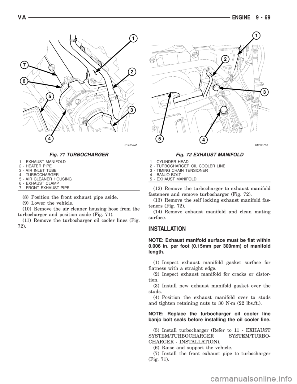
(10) Remove the air cleaner housing hose from the
turbocharger and position aside (Fig. 71).
(11) Remove the turbocharger oil cooler lines (Fig.
72).(12) Remove the turbocharger to exhaust manifold
fasteners and remove turbocharger (Fig. 72).
(13) Remove the self locking exhaust manifold fas-
teners (Fig. 72).
(14) Remove exhaust manifold and clean mating
surface.
INSTALLATION
NOTE: Exhaust manifold surface must be flat within
0.006 in. per foot (0.15mm per 300mm) of manifold
length.
(1) Inspect exhaust manifold gasket surface for
flatness with a straight edge.
(2) Inspect exhaust manifold for cracks or distor-
tion.
(3) Install new exhaust manifold gasket over the
studs.
(4) Position the exhaust manifold over to studs
and tighten retaining nuts to 30 N´m (22 lbs.ft.).
NOTE: Replace the turbocharger oil cooler line
banjo bolt seals before installing the oil cooler line.
(5) Install turbocharger (Refer to 11 - EXHAUST
SYSTEM/TURBOCHARGER SYSTEM/TURBO-
CHARGER - INSTALLATION).
(6) Raise and support the vehicle.
(7) Install the front exhaust pipe to turbocharger
(Fig. 71).
Fig. 71 TURBOCHARGER
1 - EXHAUST MANIFOLD
2 - HEATER PIPE
3 - AIR INLET TUBE
4 - TURBOCHARGER
5 - AIR CLEANER HOUSING
6 - EXHAUST CLAMP
7 - FRONT EXHAUST PIPE
Fig. 72 EXHAUST MANIFOLD
1 - CYLINDER HEAD
2 - TURBOCHARGER OIL COOLER LINE
3 - TIMING CHAIN TENSIONER
4 - BANJO BOLT
5 - EXHAUST MANIFOLD
VAENGINE 9 - 69