2006 MERCEDES-BENZ SPRINTER heater
[x] Cancel search: heaterPage 2043 of 2305
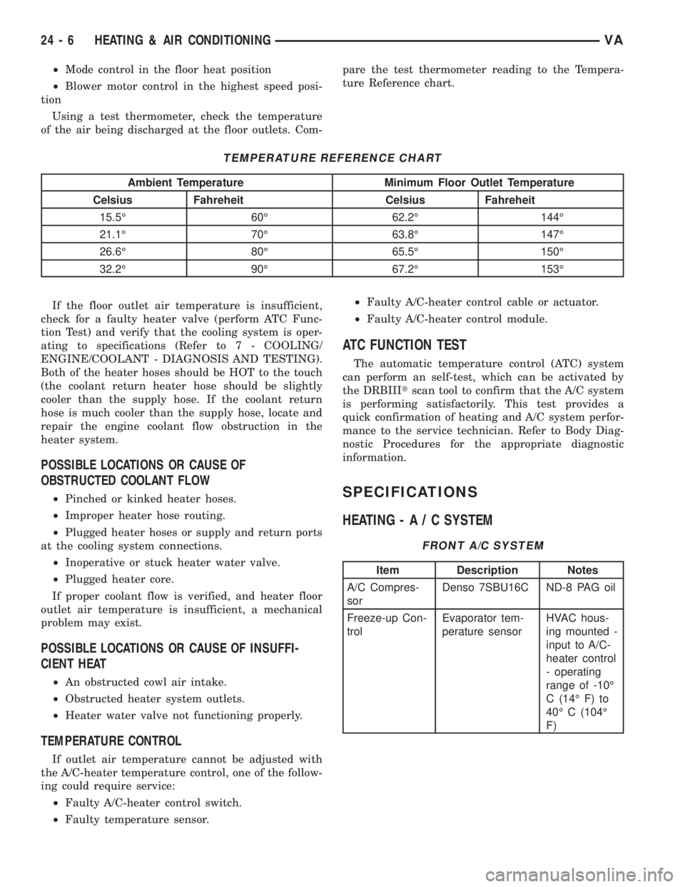
²Mode control in the floor heat position
²Blower motor control in the highest speed posi-
tion
Using a test thermometer, check the temperature
of the air being discharged at the floor outlets. Com-pare the test thermometer reading to the Tempera-
ture Reference chart.
TEMPERATURE REFERENCE CHART
Ambient Temperature Minimum Floor Outlet Temperature
Celsius Fahreheit Celsius Fahreheit
15.5É 60É 62.2É 144É
21.1É 70É 63.8É 147É
26.6É 80É 65.5É 150É
32.2É 90É 67.2É 153É
If the floor outlet air temperature is insufficient,
check for a faulty heater valve (perform ATC Func-
tion Test) and verify that the cooling system is oper-
ating to specifications (Refer to 7 - COOLING/
ENGINE/COOLANT - DIAGNOSIS AND TESTING).
Both of the heater hoses should be HOT to the touch
(the coolant return heater hose should be slightly
cooler than the supply hose. If the coolant return
hose is much cooler than the supply hose, locate and
repair the engine coolant flow obstruction in the
heater system.
POSSIBLE LOCATIONS OR CAUSE OF
OBSTRUCTED COOLANT FLOW
²Pinched or kinked heater hoses.
²Improper heater hose routing.
²Plugged heater hoses or supply and return ports
at the cooling system connections.
²Inoperative or stuck heater water valve.
²Plugged heater core.
If proper coolant flow is verified, and heater floor
outlet air temperature is insufficient, a mechanical
problem may exist.
POSSIBLE LOCATIONS OR CAUSE OF INSUFFI-
CIENT HEAT
²An obstructed cowl air intake.
²Obstructed heater system outlets.
²Heater water valve not functioning properly.
TEMPERATURE CONTROL
If outlet air temperature cannot be adjusted with
the A/C-heater temperature control, one of the follow-
ing could require service:
²Faulty A/C-heater control switch.
²Faulty temperature sensor.²Faulty A/C-heater control cable or actuator.
²Faulty A/C-heater control module.
ATC FUNCTION TEST
The automatic temperature control (ATC) system
can perform an self-test, which can be activated by
the DRBIIItscan tool to confirm that the A/C system
is performing satisfactorily. This test provides a
quick confirmation of heating and A/C system perfor-
mance to the service technician. Refer to Body Diag-
nostic Procedures for the appropriate diagnostic
information.
SPECIFICATIONS
HEATING-A/CSYSTEM
FRONT A/C SYSTEM
Item Description Notes
A/C Compres-
sorDenso 7SBU16C ND-8 PAG oil
Freeze-up Con-
trolEvaporator tem-
perature sensorHVAC hous-
ing mounted -
input to A/C-
heater control
- operating
range of -10É
C (14É F) to
40É C (104É
F)
24 - 6 HEATING & AIR CONDITIONINGVA
Page 2045 of 2305
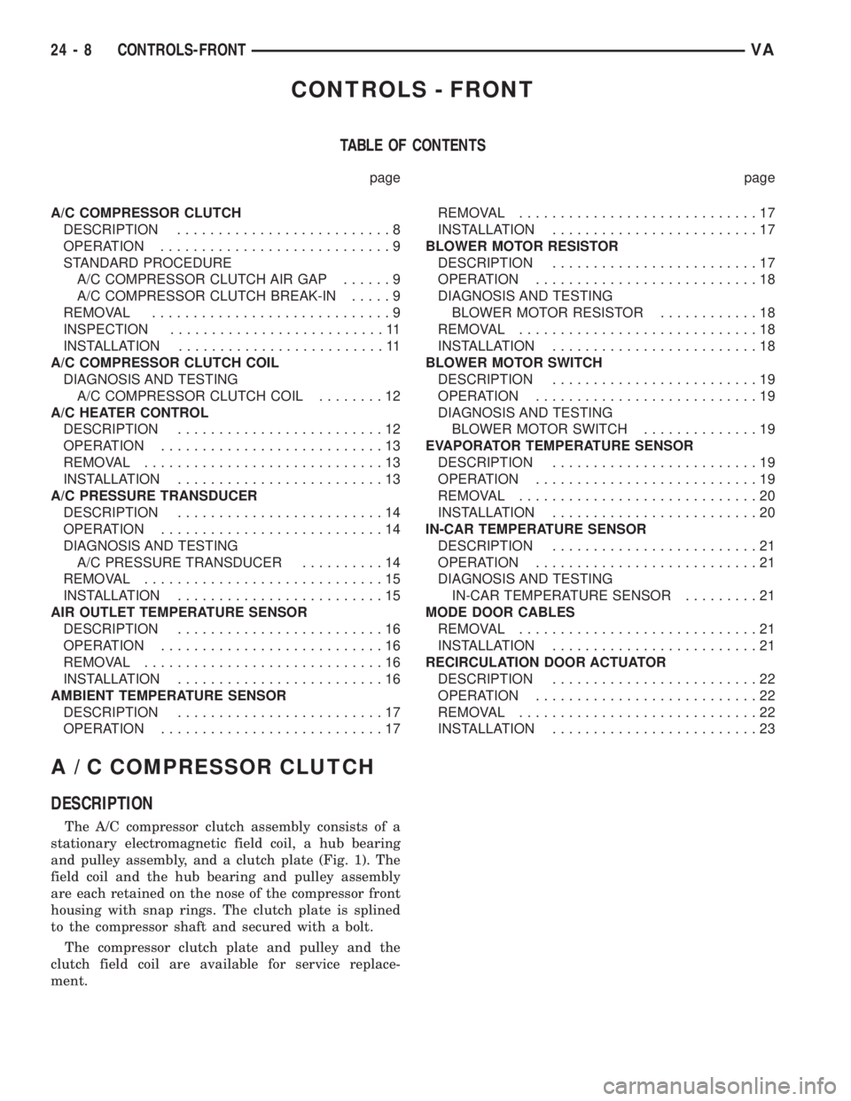
CONTROLS - FRONT
TABLE OF CONTENTS
page page
A/C COMPRESSOR CLUTCH
DESCRIPTION..........................8
OPERATION............................9
STANDARD PROCEDURE
A/C COMPRESSOR CLUTCH AIR GAP......9
A/C COMPRESSOR CLUTCH BREAK-IN.....9
REMOVAL.............................9
INSPECTION..........................11
INSTALLATION.........................11
A/C COMPRESSOR CLUTCH COIL
DIAGNOSIS AND TESTING
A/C COMPRESSOR CLUTCH COIL........12
A/C HEATER CONTROL
DESCRIPTION.........................12
OPERATION...........................13
REMOVAL.............................13
INSTALLATION.........................13
A/C PRESSURE TRANSDUCER
DESCRIPTION.........................14
OPERATION...........................14
DIAGNOSIS AND TESTING
A/C PRESSURE TRANSDUCER..........14
REMOVAL.............................15
INSTALLATION.........................15
AIR OUTLET TEMPERATURE SENSOR
DESCRIPTION.........................16
OPERATION...........................16
REMOVAL.............................16
INSTALLATION.........................16
AMBIENT TEMPERATURE SENSOR
DESCRIPTION.........................17
OPERATION...........................17REMOVAL.............................17
INSTALLATION.........................17
BLOWER MOTOR RESISTOR
DESCRIPTION.........................17
OPERATION...........................18
DIAGNOSIS AND TESTING
BLOWER MOTOR RESISTOR............18
REMOVAL.............................18
INSTALLATION.........................18
BLOWER MOTOR SWITCH
DESCRIPTION.........................19
OPERATION...........................19
DIAGNOSIS AND TESTING
BLOWER MOTOR SWITCH..............19
EVAPORATOR TEMPERATURE SENSOR
DESCRIPTION.........................19
OPERATION...........................19
REMOVAL.............................20
INSTALLATION.........................20
IN-CAR TEMPERATURE SENSOR
DESCRIPTION.........................21
OPERATION...........................21
DIAGNOSIS AND TESTING
IN-CAR TEMPERATURE SENSOR.........21
MODE DOOR CABLES
REMOVAL.............................21
INSTALLATION.........................21
RECIRCULATION DOOR ACTUATOR
DESCRIPTION.........................22
OPERATION...........................22
REMOVAL.............................22
INSTALLATION.........................23
A / C COMPRESSOR CLUTCH
DESCRIPTION
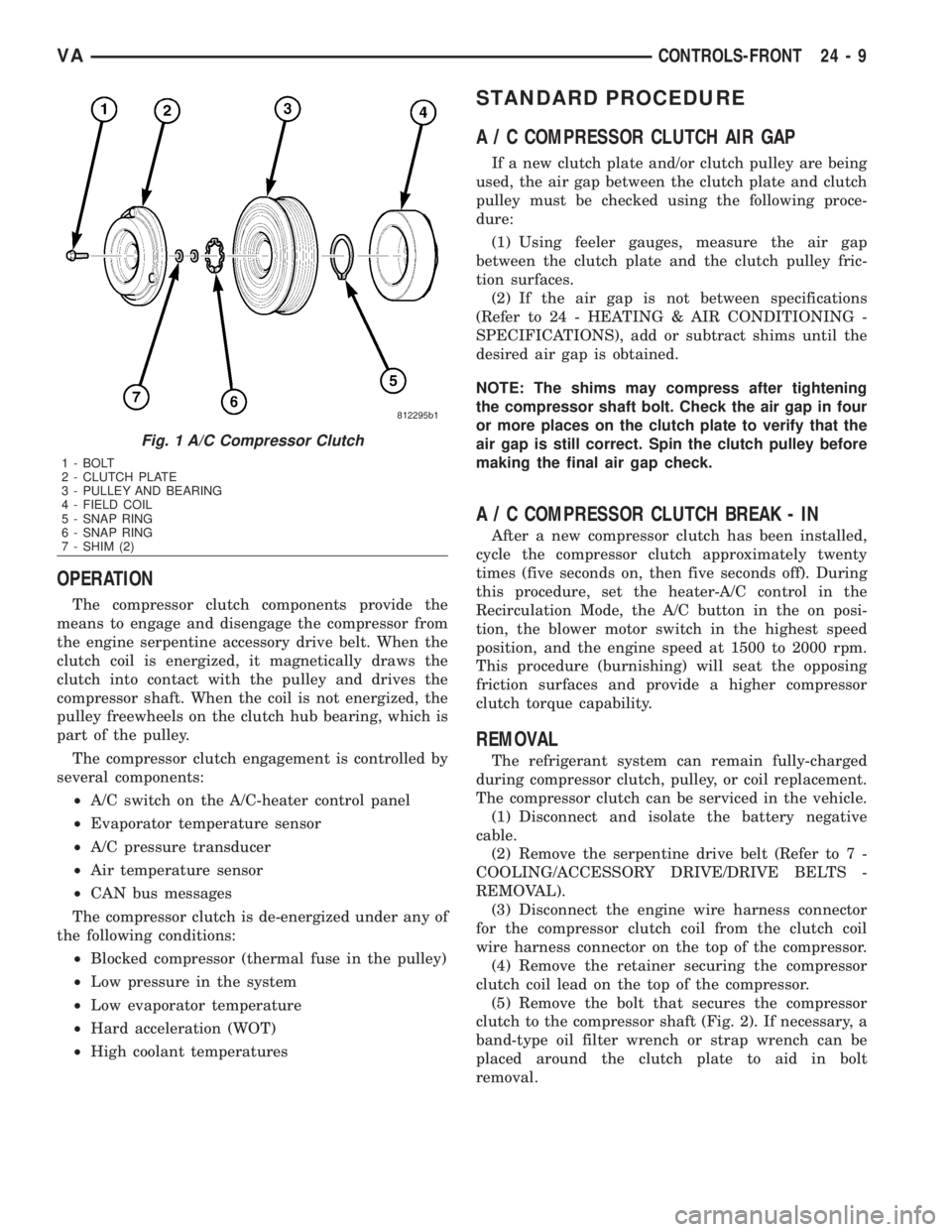
The A/C compressor clutch assembly consists of a
stationary electromagnetic field coil, a hub bearing
and pulley assembly, and a clutch plate (Fig. 1). The
field coil and the hub bearing and pulley assembly
are each retained on the nose of the compressor front
housing with snap rings. The clutch plate is splined
to the compressor shaft and secured with a bolt.
The compressor clutch plate and pulley and the
clutch field coil are available for service replace-
ment.
24 - 8 CONTROLS-FRONTVA
Page 2046 of 2305
OPERATION
The compressor clutch components provide the
means to engage and disengage the compressor from
the engine serpentine accessory drive belt. When the
clutch coil is energized, it magnetically draws the
clutch into contact with the pulley and drives the
compressor shaft. When the coil is not energized, the
pulley freewheels on the clutch hub bearing, which is
part of the pulley.
The compressor clutch engagement is controlled by
several components:
²A/C switch on the A/C-heater control panel
²Evaporator temperature sensor
²A/C pressure transducer
²Air temperature sensor
²CAN bus messages
The compressor clutch is de-energized under any of
the following conditions:
²Blocked compressor (thermal fuse in the pulley)
²Low pressure in the system
²Low evaporator temperature
²Hard acceleration (WOT)
²High coolant temperatures
STANDARD PROCEDURE
A / C COMPRESSOR CLUTCH AIR GAP
If a new clutch plate and/or clutch pulley are being
used, the air gap between the clutch plate and clutch
pulley must be checked using the following proce-
dure:
(1) Using feeler gauges, measure the air gap
between the clutch plate and the clutch pulley fric-
tion surfaces.
(2) If the air gap is not between specifications
(Refer to 24 - HEATING & AIR CONDITIONING -
SPECIFICATIONS), add or subtract shims until the
desired air gap is obtained.
NOTE: The shims may compress after tightening
the compressor shaft bolt. Check the air gap in four
or more places on the clutch plate to verify that the
air gap is still correct. Spin the clutch pulley before
making the final air gap check.
A / C COMPRESSOR CLUTCH BREAK - IN
After a new compressor clutch has been installed,
cycle the compressor clutch approximately twenty
times (five seconds on, then five seconds off). During
this procedure, set the heater-A/C control in the
Recirculation Mode, the A/C button in the on posi-
tion, the blower motor switch in the highest speed
position, and the engine speed at 1500 to 2000 rpm.
This procedure (burnishing) will seat the opposing
friction surfaces and provide a higher compressor
clutch torque capability.
REMOVAL
The refrigerant system can remain fully-charged
during compressor clutch, pulley, or coil replacement.
The compressor clutch can be serviced in the vehicle.
(1) Disconnect and isolate the battery negative
cable.
(2) Remove the serpentine drive belt (Refer to 7 -
COOLING/ACCESSORY DRIVE/DRIVE BELTS -
REMOVAL).
(3) Disconnect the engine wire harness connector
for the compressor clutch coil from the clutch coil
wire harness connector on the top of the compressor.
(4) Remove the retainer securing the compressor
clutch coil lead on the top of the compressor.
(5) Remove the bolt that secures the compressor
clutch to the compressor shaft (Fig. 2). If necessary, a
band-type oil filter wrench or strap wrench can be
placed around the clutch plate to aid in bolt
removal.
Fig. 1 A/C Compressor Clutch
1 - BOLT
2 - CLUTCH PLATE
3 - PULLEY AND BEARING
4 - FIELD COIL
5 - SNAP RING
6 - SNAP RING
7 - SHIM (2)
VACONTROLS-FRONT 24 - 9
Page 2049 of 2305
front cover of the compressor. Be certain that the
snap ring is properly fully and properly seated in the
groove.
(6) If the original clutch plate and clutch pulley
are to be reused, reinstall the original shim(s) on the
compressor shaft against the shoulder. If a new
clutch plate and/or clutch pulley are being used,
install a trial stack of shims 1.0 mm (0.040 in.) thick
on the compressor shaft against the shoulder.
(7) Install the clutch plate onto the compressor
shaft.
(8) Install and tighten the compressor shaft bolt. If
necessary, a band-type oil filter wrench or a strap
wrench can be placed around the clutch plate to aid
in bolt tightening. Tighten the bolt to 17.5 N´m (155
in. lbs.).
NOTE: The shims may compress after tightening
the shaft bolt. Check the air gap in four or more
places to verify the air gap is still correct. Spin the
pulley before performing a final check of the air
gap.
(9) If a new clutch plate and/or clutch pulley are
being installed, the air gap between the clutch plate
and clutch pulley must be checked (Refer to 24 -
HEATING & AIR CONDITIONING/CONTROLS/A/C
COMPRESSOR CLUTCH - STANDARD PROCE-
DURE).
(10) Install the retainer that secures the compres-
sor clutch coil lead to the top of the compressor.
(11) Reconnect the engine wire harness connector
to the clutch coil lead on the top of the compressor.
(12) Reinstall the serpentine accessory drive belt
(Refer to 7 - COOLING/ACCESSORY DRIVE/DRIVE
BELTS - INSTALLATION).
(13) Reconnect the battery negative cable.
(14) If a new clutch plate and/or clutch pulley are
being installed, the new clutch components must be
burnished (Refer to 24 - HEATING & AIR CONDI-
TIONING/CONTROLS/A/C COMPRESSOR CLUTCH
- STANDARD PROCEDURE).
A / C COMPRESSOR CLUTCH
COIL
DIAGNOSIS AND TESTING
A / C COMPRESSOR CLUTCH COIL
The air conditioning compressor clutch coil electri-
cal circuit is controlled by the ATC control module
which is integral to the heater-A/C control. Begin
testing of a suspected compressor clutch coil problem
by performing the ATC Function Test using the
DRBIIItscan tool.PRELIMINARY CHECKS
(1) If no diagnostic trouble codes (DTCs) are found
in the A/C-heater control or the powertrain control
module (PCM), go to Step 2. If any DTCs are found,
repair as required.
(2) If the A/C compressor clutch still will not
engage, verify the refrigerant charge level (Refer to
24 - HEATING & AIR CONDITIONING/PLUMBING
- DIAGNOSIS AND TESTING - REFRIGERANT
SYSTEM LEAKS). If the refrigerant charge level is
OK, go to TESTS. If the refrigerant charge level is
not OK, adjust the refrigerant charge as required.
TESTS
(1) Verify the battery state of charge (Refer to 8 -
ELECTRICAL/BATTERY SYSTEM/BATTERY -
DIAGNOSIS AND TESTING).
(2) Connect an ammeter (0 to 10 ampere scale
selected) in series with the clutch coil feed terminal.
Connect a voltmeter (0 to 20 volt scale selected) to
measure voltage across the battery and the clutch
coil.
(3) With the A/C-heater control in the A/C mode
and the blower motor at low speed, start the engine
and allow it to run at a normal idle speed.
(4) The A/C compressor clutch should engage
immediately, and the clutch coil supply voltage
should be within two volts of the battery voltage. If
the coil supply voltage is OK, go to Step 5. If the coil
supply voltage is not within two volts of battery volt-
age, test the clutch coil feed circuit for excessive volt-
age drop and repair as necessary.
(5) For the acceptable A/C clutch coil current draw
specifications refer to 24 - HEATING & AIR CONDI-
TIONING - SPECIFICATIONS. Specifications apply
for a work area temperature of 21É C (70É F). If volt-
age is more than 12.5 volts, add electrical loads by
turning on electrical accessories until voltage reads
below 12.5 volts.
(a) If the A/C clutch coil current reading is zero,
the coil is open and must be replaced.
(b) If the A/C clutch coil current reading is above
specifications, the coil is shorted and must be
replaced.
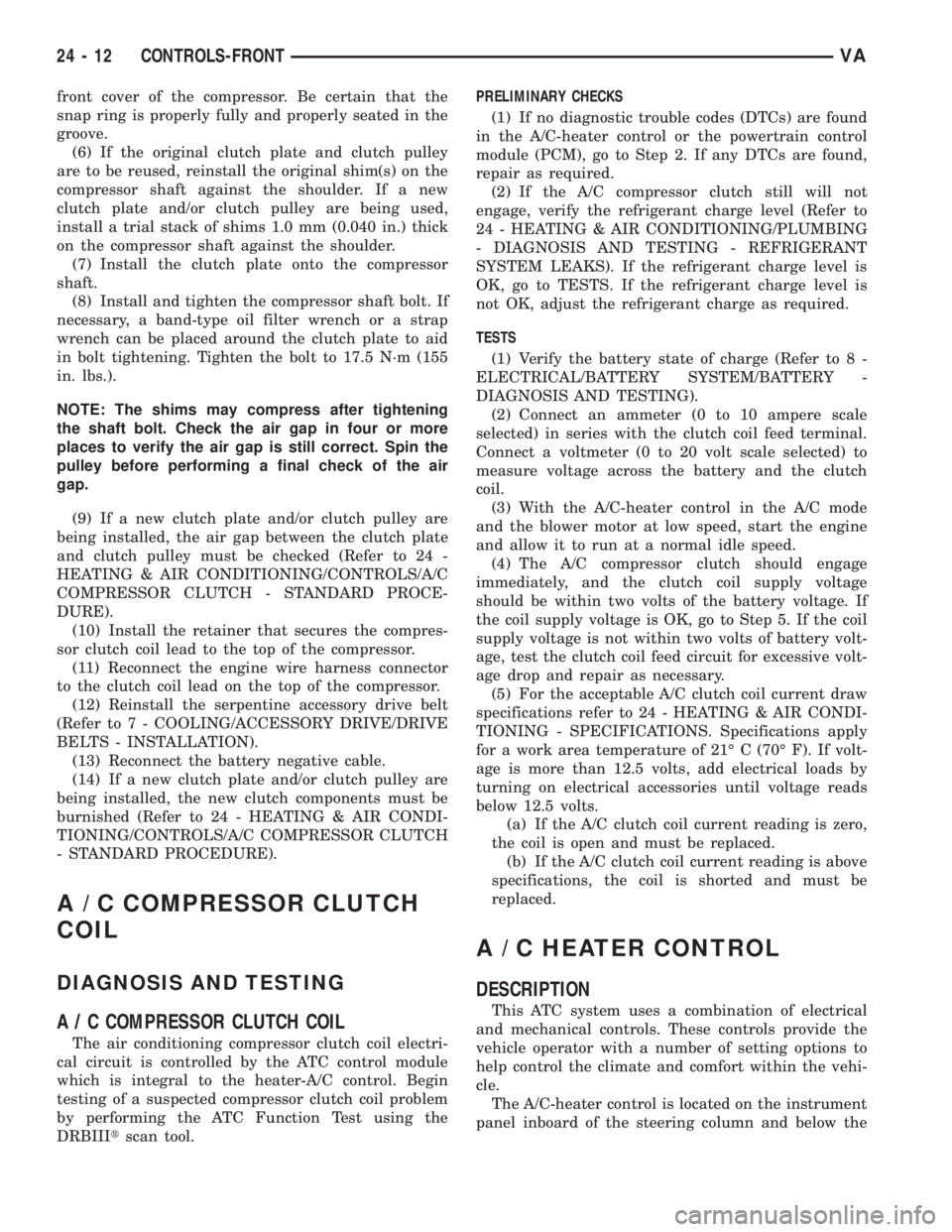
A / C HEATER CONTROL
DESCRIPTION
This ATC system uses a combination of electrical
and mechanical controls. These controls provide the
vehicle operator with a number of setting options to
help control the climate and comfort within the vehi-
cle.
The A/C-heater control is located on the instrument
panel inboard of the steering column and below the
24 - 12 CONTROLS-FRONTVA
Page 2050 of 2305
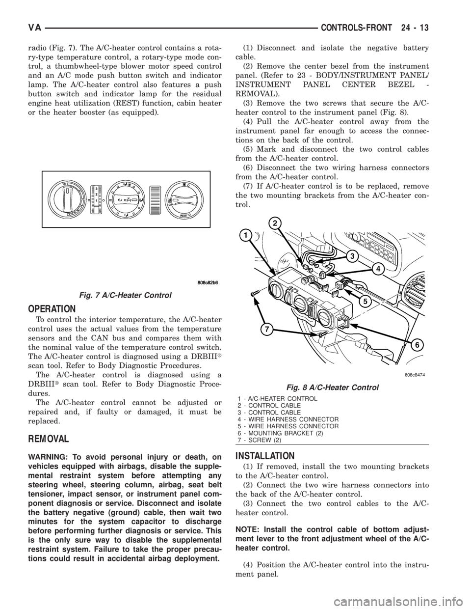
radio (Fig. 7). The A/C-heater control contains a rota-
ry-type temperature control, a rotary-type mode con-
trol, a thumbwheel-type blower motor speed control
and an A/C mode push button switch and indicator
lamp. The A/C-heater control also features a push
button switch and indicator lamp for the residual
engine heat utilization (REST) function, cabin heater
or the heater booster (as equipped).
OPERATION
To control the interior temperature, the A/C-heater
control uses the actual values from the temperature
sensors and the CAN bus and compares them with
the nominal value of the temperature control switch.
The A/C-heater control is diagnosed using a DRBIIIt
scan tool. Refer to Body Diagnostic Procedures.
The A/C-heater control is diagnosed using a
DRBIIItscan tool. Refer to Body Diagnostic Proce-
dures.
The A/C-heater control cannot be adjusted or
repaired and, if faulty or damaged, it must be
replaced.
REMOVAL
WARNING: To avoid personal injury or death, on
vehicles equipped with airbags, disable the supple-
mental restraint system before attempting any
steering wheel, steering column, airbag, seat belt
tensioner, impact sensor, or instrument panel com-
ponent diagnosis or service. Disconnect and isolate
the battery negative (ground) cable, then wait two
minutes for the system capacitor to discharge
before performing further diagnosis or service. This
is the only sure way to disable the supplemental
restraint system. Failure to take the proper precau-
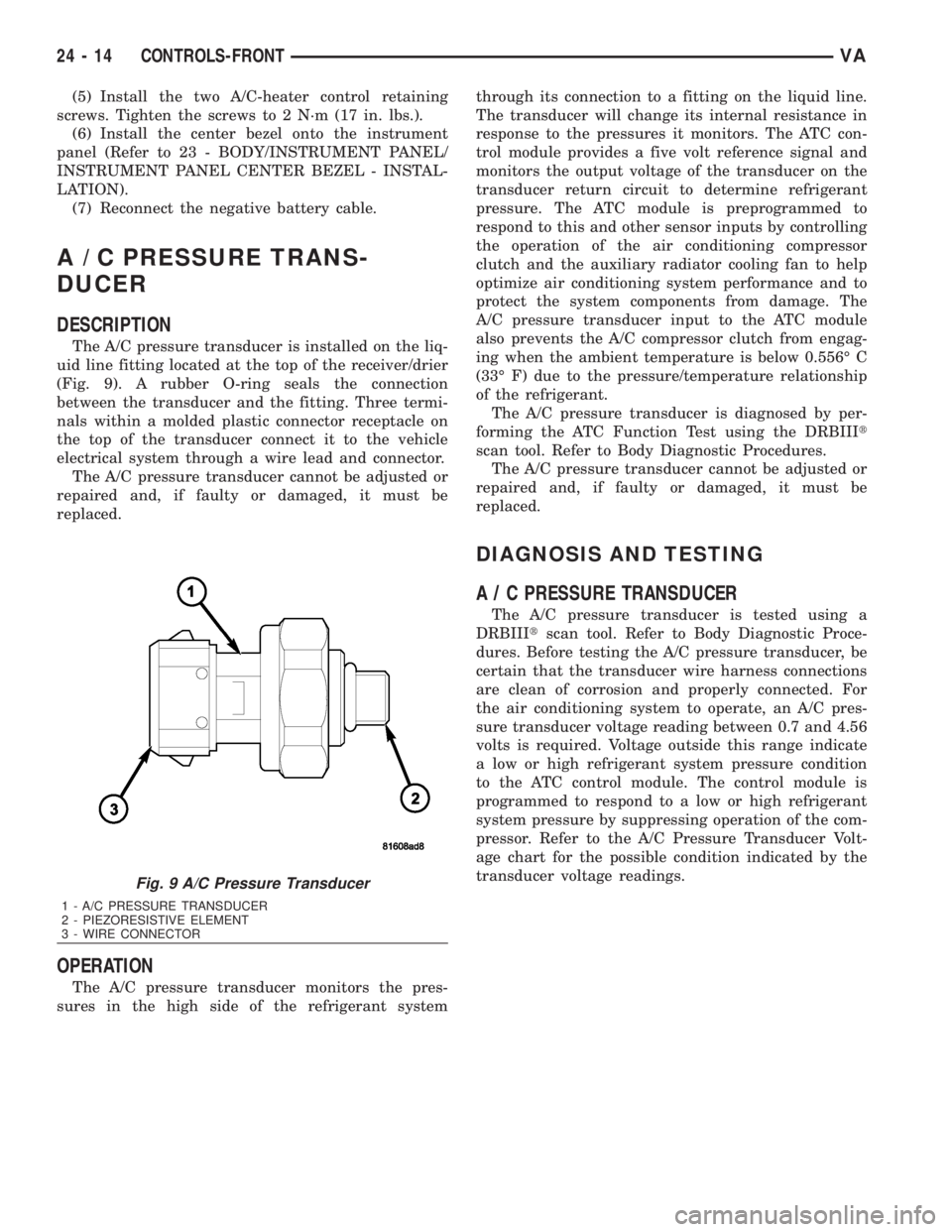
tions could result in accidental airbag deployment.(1) Disconnect and isolate the negative battery
cable.
(2) Remove the center bezel from the instrument
panel. (Refer to 23 - BODY/INSTRUMENT PANEL/
INSTRUMENT PANEL CENTER BEZEL -
REMOVAL).
(3) Remove the two screws that secure the A/C-
heater control to the instrument panel (Fig. 8).
(4) Pull the A/C-heater control away from the
instrument panel far enough to access the connec-
tions on the back of the control.
(5) Mark and disconnect the two control cables
from the A/C-heater control.
(6) Disconnect the two wiring harness connectors
from the A/C-heater control.
(7) If A/C-heater control is to be replaced, remove
the two mounting brackets from the A/C-heater con-
trol.INSTALLATION
(1) If removed, install the two mounting brackets
to the A/C-heater control.
(2) Connect the two wire harness connectors into
the back of the A/C-heater control.
(3) Connect the two control cables to the A/C-
heater control.
NOTE: Install the control cable of bottom adjust-
ment lever to the front adjustment wheel of the A/C-
heater control.
(4) Position the A/C-heater control into the instru-
ment panel.
Fig. 7 A/C-Heater Control
Fig. 8 A/C-Heater Control
1 - A/C-HEATER CONTROL
2 - CONTROL CABLE
3 - CONTROL CABLE
4 - WIRE HARNESS CONNECTOR
5 - WIRE HARNESS CONNECTOR
6 - MOUNTING BRACKET (2)
7 - SCREW (2)
VACONTROLS-FRONT 24 - 13
Page 2051 of 2305
(5) Install the two A/C-heater control retaining
screws. Tighten the screws to 2 N´m (17 in. lbs.).
(6) Install the center bezel onto the instrument
panel (Refer to 23 - BODY/INSTRUMENT PANEL/
INSTRUMENT PANEL CENTER BEZEL - INSTAL-
LATION).
(7) Reconnect the negative battery cable.
A / C PRESSURE TRANS-
DUCER
DESCRIPTION
The A/C pressure transducer is installed on the liq-
uid line fitting located at the top of the receiver/drier
(Fig. 9). A rubber O-ring seals the connection
between the transducer and the fitting. Three termi-
nals within a molded plastic connector receptacle on
the top of the transducer connect it to the vehicle
electrical system through a wire lead and connector.
The A/C pressure transducer cannot be adjusted or
repaired and, if faulty or damaged, it must be
replaced.
OPERATION
The A/C pressure transducer monitors the pres-
sures in the high side of the refrigerant systemthrough its connection to a fitting on the liquid line.
The transducer will change its internal resistance in
response to the pressures it monitors. The ATC con-
trol module provides a five volt reference signal and
monitors the output voltage of the transducer on the
transducer return circuit to determine refrigerant
pressure. The ATC module is preprogrammed to
respond to this and other sensor inputs by controlling
the operation of the air conditioning compressor
clutch and the auxiliary radiator cooling fan to help
optimize air conditioning system performance and to
protect the system components from damage. The
A/C pressure transducer input to the ATC module
also prevents the A/C compressor clutch from engag-
ing when the ambient temperature is below 0.556É C
(33É F) due to the pressure/temperature relationship
of the refrigerant.
The A/C pressure transducer is diagnosed by per-
forming the ATC Function Test using the DRBIIIt
scan tool. Refer to Body Diagnostic Procedures.
The A/C pressure transducer cannot be adjusted or
repaired and, if faulty or damaged, it must be
replaced.
DIAGNOSIS AND TESTING
A / C PRESSURE TRANSDUCER
The A/C pressure transducer is tested using a
DRBIIItscan tool. Refer to Body Diagnostic Proce-
dures. Before testing the A/C pressure transducer, be
certain that the transducer wire harness connections
are clean of corrosion and properly connected. For
the air conditioning system to operate, an A/C pres-
sure transducer voltage reading between 0.7 and 4.56
volts is required. Voltage outside this range indicate
a low or high refrigerant system pressure condition
to the ATC control module. The control module is
programmed to respond to a low or high refrigerant
system pressure by suppressing operation of the com-
pressor. Refer to the A/C Pressure Transducer Volt-
age chart for the possible condition indicated by the
transducer voltage readings.
Fig. 9 A/C Pressure Transducer
1 - A/C PRESSURE TRANSDUCER
2 - PIEZORESISTIVE ELEMENT
3 - WIRE CONNECTOR
24 - 14 CONTROLS-FRONTVA
Page 2053 of 2305
(6) Charge the refrigerant system (Refer to 24 -
HEATING & AIR CONDITIONING/PLUMBING -
STANDARD PROCEDURE).
AIR OUTLET TEMPERATURE
SENSOR
DESCRIPTION
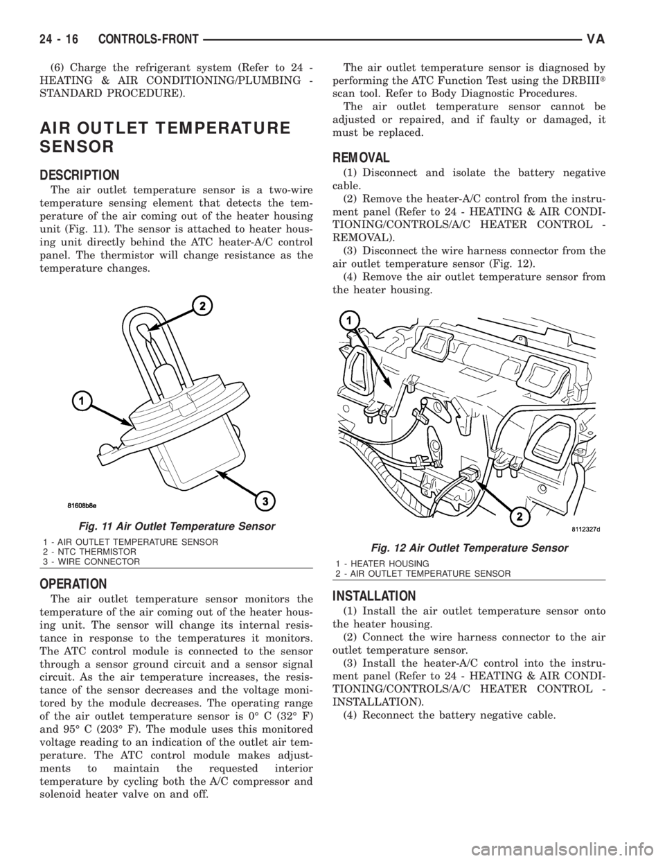
The air outlet temperature sensor is a two-wire
temperature sensing element that detects the tem-
perature of the air coming out of the heater housing
unit (Fig. 11). The sensor is attached to heater hous-
ing unit directly behind the ATC heater-A/C control
panel. The thermistor will change resistance as the
temperature changes.
OPERATION
The air outlet temperature sensor monitors the
temperature of the air coming out of the heater hous-
ing unit. The sensor will change its internal resis-
tance in response to the temperatures it monitors.
The ATC control module is connected to the sensor
through a sensor ground circuit and a sensor signal
circuit. As the air temperature increases, the resis-
tance of the sensor decreases and the voltage moni-
tored by the module decreases. The operating range
of the air outlet temperature sensor is 0É C (32É F)
and 95É C (203É F). The module uses this monitored
voltage reading to an indication of the outlet air tem-
perature. The ATC control module makes adjust-
ments to maintain the requested interior
temperature by cycling both the A/C compressor and
solenoid heater valve on and off.The air outlet temperature sensor is diagnosed by
performing the ATC Function Test using the DRBIIIt
scan tool. Refer to Body Diagnostic Procedures.
The air outlet temperature sensor cannot be
adjusted or repaired, and if faulty or damaged, it
must be replaced.
REMOVAL
(1) Disconnect and isolate the battery negative
cable.
(2) Remove the heater-A/C control from the instru-
ment panel (Refer to 24 - HEATING & AIR CONDI-
TIONING/CONTROLS/A/C HEATER CONTROL -
REMOVAL).
(3) Disconnect the wire harness connector from the
air outlet temperature sensor (Fig. 12).
(4) Remove the air outlet temperature sensor from
the heater housing.
INSTALLATION
(1) Install the air outlet temperature sensor onto
the heater housing.
(2) Connect the wire harness connector to the air
outlet temperature sensor.
(3) Install the heater-A/C control into the instru-
ment panel (Refer to 24 - HEATING & AIR CONDI-
TIONING/CONTROLS/A/C HEATER CONTROL -
INSTALLATION).
(4) Reconnect the battery negative cable.
Fig. 11 Air Outlet Temperature Sensor
1 - AIR OUTLET TEMPERATURE SENSOR
2 - NTC THERMISTOR
3 - WIRE CONNECTORFig. 12 Air Outlet Temperature Sensor
1 - HEATER HOUSING
2 - AIR OUTLET TEMPERATURE SENSOR
24 - 16 CONTROLS-FRONTVA
Page 2056 of 2305
BLOWER MOTOR SWITCH
DESCRIPTION
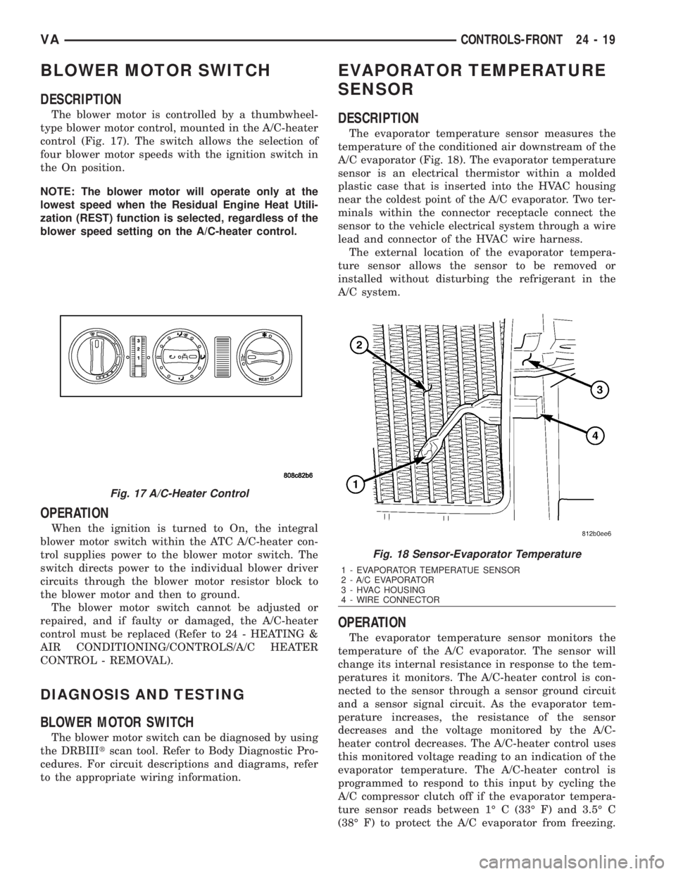
The blower motor is controlled by a thumbwheel-
type blower motor control, mounted in the A/C-heater
control (Fig. 17). The switch allows the selection of
four blower motor speeds with the ignition switch in
the On position.
NOTE: The blower motor will operate only at the
lowest speed when the Residual Engine Heat Utili-
zation (REST) function is selected, regardless of the
blower speed setting on the A/C-heater control.
OPERATION
When the ignition is turned to On, the integral
blower motor switch within the ATC A/C-heater con-
trol supplies power to the blower motor switch. The
switch directs power to the individual blower driver
circuits through the blower motor resistor block to
the blower motor and then to ground.
The blower motor switch cannot be adjusted or
repaired, and if faulty or damaged, the A/C-heater
control must be replaced (Refer to 24 - HEATING &
AIR CONDITIONING/CONTROLS/A/C HEATER
CONTROL - REMOVAL).
DIAGNOSIS AND TESTING
BLOWER MOTOR SWITCH
The blower motor switch can be diagnosed by using
the DRBIIItscan tool. Refer to Body Diagnostic Pro-
cedures. For circuit descriptions and diagrams, refer
to the appropriate wiring information.
EVAPORATOR TEMPERATURE
SENSOR
DESCRIPTION
The evaporator temperature sensor measures the
temperature of the conditioned air downstream of the
A/C evaporator (Fig. 18). The evaporator temperature
sensor is an electrical thermistor within a molded
plastic case that is inserted into the HVAC housing
near the coldest point of the A/C evaporator. Two ter-
minals within the connector receptacle connect the
sensor to the vehicle electrical system through a wire
lead and connector of the HVAC wire harness.
The external location of the evaporator tempera-
ture sensor allows the sensor to be removed or
installed without disturbing the refrigerant in the
A/C system.
OPERATION
The evaporator temperature sensor monitors the
temperature of the A/C evaporator. The sensor will
change its internal resistance in response to the tem-
peratures it monitors. The A/C-heater control is con-
nected to the sensor through a sensor ground circuit
and a sensor signal circuit. As the evaporator tem-
perature increases, the resistance of the sensor
decreases and the voltage monitored by the A/C-
heater control decreases. The A/C-heater control uses
this monitored voltage reading to an indication of the
evaporator temperature. The A/C-heater control is
programmed to respond to this input by cycling the
A/C compressor clutch off if the evaporator tempera-
ture sensor reads between 1É C (33É F) and 3.5É C
(38É F) to protect the A/C evaporator from freezing.
Fig. 17 A/C-Heater Control
Fig. 18 Sensor-Evaporator Temperature
1 - EVAPORATOR TEMPERATUE SENSOR
2 - A/C EVAPORATOR
3 - HVAC HOUSING
4 - WIRE CONNECTOR
VACONTROLS-FRONT 24 - 19