2006 MERCEDES-BENZ SPRINTER airbag
[x] Cancel search: airbagPage 966 of 2305
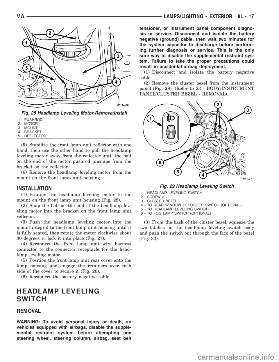
(5) Stabilize the front lamp unit reflector with one
hand, then use the other hand to pull the headlamp
leveling motor away from the reflector until the ball
on the end of the motor pushrod unsnaps from the
bracket on the reflector.
(6) Remove the headlamp leveling motor from the
mount on the front lamp unit housing.
INSTALLATION
(1) Position the headlamp leveling motor to the
mount on the front lamp unit housing (Fig. 28).
(2) Snap the ball on the end of the headlamp lev-
eling motor into the bracket on the front lamp unit
reflector.
(3) Push the headlamp leveling motor into the
mount integral to the front lamp unit housing until it
is fully seated, then rotate the motor clockwise about
30 degrees to lock it into place (Fig. 27).
(4) Reconnect the front lamp unit wire harness
connector to the connector receptacle for the head-
lamp leveling motor.
(5) Position the front lamp unit rear cover onto the
lamp housing and engage the retainers over each
side of the cover to secure it (Fig. 26).
(6) Reconnect the battery negative cable.
HEADLAMP LEVELING
SWITCH
REMOVAL
WARNING: To avoid personal injury or death, on
vehicles equipped with airbags, disable the supple-
mental restraint system before attempting any
steering wheel, steering column, airbag, seat belttensioner, or instrument panel component diagno-
sis or service. Disconnect and isolate the battery
negative (ground) cable, then wait two minutes for
the system capacitor to discharge before perform-
ing further diagnosis or service. This is the only
sure way to disable the supplemental restraint sys-
tem. Failure to take the proper precautions could
result in accidental airbag deployment.
(1) Disconnect and isolate the battery negative
cable.
(2) Remove the cluster bezel from the instrument
panel (Fig. 29). (Refer to 23 - BODY/INSTRUMENT
PANEL/CLUSTER BEZEL - REMOVAL).
(3) From the back of the cluster bezel, squeeze the
two latches on the headlamp leveling switch body
and push the switch out through the face of the bezel
(Fig. 30).
Fig. 28 Headlamp Leveling Motor Remove/Install
1 - PUSHROD
2 - MOTOR
3 - MOUNT
4 - BRACKET
5 - REFLECTOR
Fig. 29 Headlamp Leveling Switch
1 - HEADLAMP LEVELING SWITCH
2 - SCREW (2)
3 - CLUSTER BEZEL
4 - TO REAR WINDOW DEFOGGER SWITCH (OPTIONAL)
5 - TO HEADLAMP LEVELING SWITCH
6 - TO FOG LAMP SWITCH (OPTIONAL)
VALAMPS/LIGHTING - EXTERIOR 8L - 17
Page 967 of 2305
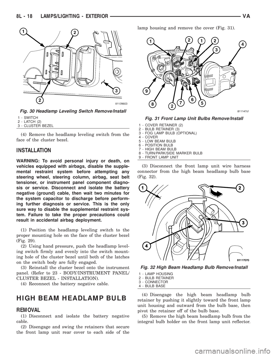
(4) Remove the headlamp leveling switch from the
face of the cluster bezel.
INSTALLATION
WARNING: To avoid personal injury or death, on
vehicles equipped with airbags, disable the supple-
mental restraint system before attempting any
steering wheel, steering column, airbag, seat belt
tensioner, or instrument panel component diagno-
sis or service. Disconnect and isolate the battery
negative (ground) cable, then wait two minutes for
the system capacitor to discharge before perform-
ing further diagnosis or service. This is the only
sure way to disable the supplemental restraint sys-
tem. Failure to take the proper precautions could
result in accidental airbag deployment.
(1) Position the headlamp leveling switch to the
proper mounting hole on the face of the cluster bezel
(Fig. 29).
(2) Using hand pressure, push the headlamp level-
ing switch firmly and evenly into the switch mount-
ing hole of the cluster bezel until both of the latches
on the switch body are fully engaged.
(3) Reinstall the cluster bezel onto the instrument
panel. (Refer to 23 - BODY/INSTRUMENT PANEL/
CLUSTER BEZEL - INSTALLATION).
(4) Reconnect the battery negative cable.
HIGH BEAM HEADLAMP BULB
REMOVAL
(1) Disconnect and isolate the battery negative
cable.
(2) Disengage and swing the retainers that secure
the front lamp unit rear cover to each side of thelamp housing and remove the cover (Fig. 31).
(3) Disconnect the front lamp unit wire harness
connector from the high beam headlamp bulb base
(Fig. 32).
(4) Disengage the high beam headlamp bulb
retainer by pushing it slightly toward the front lamp
unit housing and outward from the bulb base, then
pivot the retainer off of the bulb base.
(5) Remove the high beam headlamp bulb from the
integral bulb holder on the front lamp unit reflector.
Fig. 30 Headlamp Leveling Switch Remove/Install
1 - SWITCH
2 - LATCH (2)
3 - CLUSTER BEZELFig. 31 Front Lamp Unit Bulbs Remove/Install
1 - COVER RETAINER (2)
2 - BULB RETAINER (3)
3 - FOG LAMP BULB (OPTIONAL)
4 - COVER
5 - LOW BEAM BULB
6 - POSITION BULB
7 - HIGH BEAM BULB
8 - TURN/PARK/SIDE MARKER BULB
9 - FRONT LAMP UNIT
Fig. 32 High Beam Headlamp Bulb Remove/Install
1 - LAMP HOUSING
2 - BULB RETAINER
3 - CONNECTOR
4 - BULB BASE
8L - 18 LAMPS/LIGHTING - EXTERIORVA
Page 970 of 2305

MULTI - FUNCTION SWITCH
REMOVAL
WARNING: To avoid personal injury or death, on
vehicles equipped with airbags, disable the supple-
mental restraint system before attempting any
steering wheel, steering column, airbag, seat belt
tensioner, or instrument panel component diagno-
sis or service. Disconnect and isolate the battery
negative (ground) cable, then wait two minutes for
the system capacitor to discharge before perform-
ing further diagnosis or service. This is the only
sure way to disable the supplemental restraint sys-
tem. Failure to take the proper precautions could
result in accidental airbag deployment.
(1) Disconnect and isolate the battery negative
cable.
(2) Remove the fuse block from the underside of
the steering column. (Refer to 8 - ELECTRICAL/
POWER DISTRIBUTION/FUSE BLOCK -
REMOVAL).
(3) Remove the clockspring from the steering col-
umn. (Refer to 8 - ELECTRICAL/RESTRAINTS/
CLOCKSPRING - REMOVAL).
(4) If the vehicle is so equipped, remove the steer-
ing angle sensor from the steering column. (Refer to
5 - BRAKES/ELECTRICAL/STEERING ANGLE
SENSOR - REMOVAL).
(5) Remove the two screws that secure the upper
shroud to the top of the multi-function switch (Fig.
37).
(6) Remove the upper shroud from the top of the
multi-function switch.
(7) Remove the two screws that secure the multi-
function switch to the steering column.(8) Remove the multi-function switch from the
steering column.
(9) Remove the speed control switch from the back
of the multi-function switch. (Refer to 8 - ELECTRI-
CAL/SPEED CONTROL/SWITCH - REMOVAL).
INSTALLATION
WARNING: To avoid personal injury or death, on
vehicles equipped with airbags, disable the supple-
mental restraint system before attempting any
steering wheel, steering column, airbag, seat belt
tensioner, or instrument panel component diagno-
sis or service. Disconnect and isolate the battery
negative (ground) cable, then wait two minutes for
the system capacitor to discharge before perform-
ing further diagnosis or service. This is the only
sure way to disable the supplemental restraint sys-
tem. Failure to take the proper precautions could
result in accidental airbag deployment.
(1) Reinstall the speed control switch onto the
back of the multi-function switch. (Refer to 8 - ELEC-
TRICAL/SPEED CONTROL/SWITCH - INSTALLA-
TION).
(2) Position the multi-function switch onto the
steering column (Fig. 37).
(3) Install and tighten the two screws that secure
the multi-function switch to the steering column.
(4) Position the upper shroud onto the top of the
multi-function switch.
(5) Install and tighten the two screws that secure
the upper shroud to the top of the multi-function
switch.
(6) If the vehicle is so equipped, reinstall the steer-
ing angle sensor onto the steering column. (Refer to 5
- BRAKES/ELECTRICAL/STEERING ANGLE SEN-
SOR - INSTALLATION).
(7) Reinstall the clockspring onto the steering col-
umn. (Refer to 8 - ELECTRICAL/RESTRAINTS/
CLOCKSPRING - INSTALLATION).
(8) Reinstall the fuse block onto the underside of
the steering column. (Refer to 8 - ELECTRICAL/
POWER DISTRIBUTION/FUSE BLOCK - INSTAL-
LATION).
(9) Reconnect the battery negative cable.
PARK BRAKE SWITCH
REMOVAL
(1) Remove the trim cover from the park brake
lever (Fig. 38). (Refer to 5 - BRAKES/PARKING
BRAKE/LEVER - REMOVAL).
Fig. 37 Multi-Function Switch Remove/Install
1 - SCREW (2)
2 - UPPER SHROUD
3 - SWITCH
4 - SCREW (2)
VALAMPS/LIGHTING - EXTERIOR 8L - 21
Page 975 of 2305
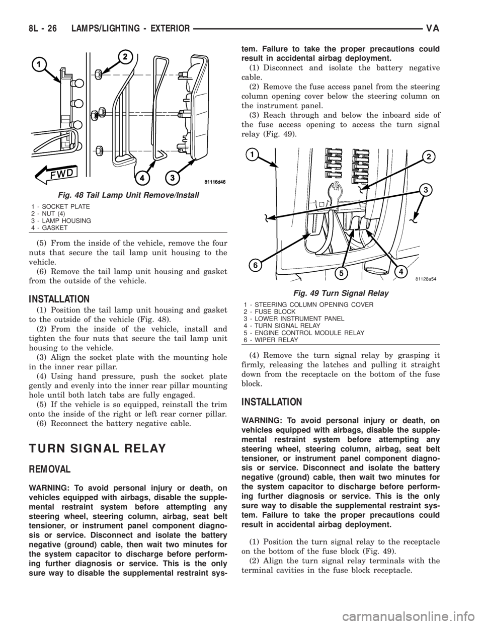
(5) From the inside of the vehicle, remove the four
nuts that secure the tail lamp unit housing to the
vehicle.
(6) Remove the tail lamp unit housing and gasket
from the outside of the vehicle.
INSTALLATION
(1) Position the tail lamp unit housing and gasket
to the outside of the vehicle (Fig. 48).
(2) From the inside of the vehicle, install and
tighten the four nuts that secure the tail lamp unit
housing to the vehicle.
(3) Align the socket plate with the mounting hole
in the inner rear pillar.
(4) Using hand pressure, push the socket plate
gently and evenly into the inner rear pillar mounting
hole until both latch tabs are fully engaged.
(5) If the vehicle is so equipped, reinstall the trim
onto the inside of the right or left rear corner pillar.
(6) Reconnect the battery negative cable.
TURN SIGNAL RELAY
REMOVAL
WARNING: To avoid personal injury or death, on
vehicles equipped with airbags, disable the supple-
mental restraint system before attempting any
steering wheel, steering column, airbag, seat belt
tensioner, or instrument panel component diagno-
sis or service. Disconnect and isolate the battery
negative (ground) cable, then wait two minutes for
the system capacitor to discharge before perform-
ing further diagnosis or service. This is the only
sure way to disable the supplemental restraint sys-tem. Failure to take the proper precautions could
result in accidental airbag deployment.
(1) Disconnect and isolate the battery negative
cable.
(2) Remove the fuse access panel from the steering
column opening cover below the steering column on
the instrument panel.
(3) Reach through and below the inboard side of
the fuse access opening to access the turn signal
relay (Fig. 49).
(4) Remove the turn signal relay by grasping it
firmly, releasing the latches and pulling it straight
down from the receptacle on the bottom of the fuse
block.
INSTALLATION
WARNING: To avoid personal injury or death, on
vehicles equipped with airbags, disable the supple-
mental restraint system before attempting any
steering wheel, steering column, airbag, seat belt
tensioner, or instrument panel component diagno-
sis or service. Disconnect and isolate the battery
negative (ground) cable, then wait two minutes for
the system capacitor to discharge before perform-
ing further diagnosis or service. This is the only
sure way to disable the supplemental restraint sys-
tem. Failure to take the proper precautions could
result in accidental airbag deployment.
(1) Position the turn signal relay to the receptacle
on the bottom of the fuse block (Fig. 49).
(2) Align the turn signal relay terminals with the
terminal cavities in the fuse block receptacle.
Fig. 48 Tail Lamp Unit Remove/Install
1 - SOCKET PLATE
2 - NUT (4)
3 - LAMP HOUSING
4 - GASKET
Fig. 49 Turn Signal Relay
1 - STEERING COLUMN OPENING COVER
2 - FUSE BLOCK
3 - LOWER INSTRUMENT PANEL
4 - TURN SIGNAL RELAY
5 - ENGINE CONTROL MODULE RELAY
6 - WIPER RELAY
8L - 26 LAMPS/LIGHTING - EXTERIORVA
Page 984 of 2305
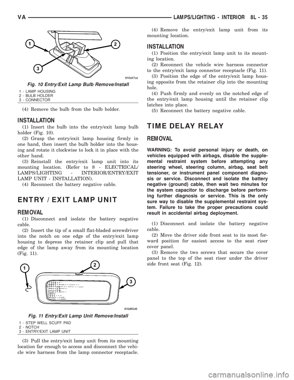
(4) Remove the bulb from the bulb holder.
INSTALLATION
(1) Insert the bulb into the entry/exit lamp bulb
holder (Fig. 10).
(2) Grasp the entry/exit lamp housing firmly in
one hand, then insert the bulb holder into the hous-
ing and rotate it clockwise to lock it in place with the
other hand.
(3) Reinstall the entry/exit lamp unit into its
mounting location. (Refer to 8 - ELECTRICAL/
LAMPS/LIGHTING - INTERIOR/ENTRY/EXIT
LAMP UNIT - INSTALLATION).
(4) Reconnect the battery negative cable.
ENTRY / EXIT LAMP UNIT
REMOVAL
(1) Disconnect and isolate the battery negative
cable.
(2) Insert the tip of a small flat-bladed screwdriver
into the notch on one edge of the entry/exit lamp
housing to depress the retainer clip and pull that
edge of the lamp away from its mounting location
(Fig. 11).
(3) Pull the entry/exit lamp unit from its mounting
location far enough to access and disconnect the vehi-
cle wire harness from the lamp connector receptacle.(4) Remove the entry/exit lamp unit from its
mounting location.
INSTALLATION
(1) Position the entry/exit lamp unit to its mount-
ing location.
(2) Reconnect the vehicle wire harness connector
to the entry/exit lamp connector receptacle (Fig. 11).
(3) Position the edge of the entry/exit lamp hous-
ing opposite from the retainer clip into the mounting
hole.
(4) Push firmly and evenly on the notched edge of
the entry/exit lamp housing until the retainer clip
latches into place.
(5) Reconnect the battery negative cable.
TIME DELAY RELAY
REMOVAL
WARNING: To avoid personal injury or death, on
vehicles equipped with airbags, disable the supple-
mental restraint system before attempting any
steering wheel, steering column, airbag, seat belt
tensioner, or instrument panel component diagno-
sis or service. Disconnect and isolate the battery
negative (ground) cable, then wait two minutes for
the system capacitor to discharge before perform-
ing further diagnosis or service. This is the only
sure way to disable the supplemental restraint sys-
tem. Failure to take the proper precautions could
result in accidental airbag deployment.
(1) Disconnect and isolate the battery negative
cable.
(2) Move the driver side front seat to its most for-
ward position for easiest access to the seat riser
cover panel.
(3) Remove the two screws that secure the cover
panel to the top of the seat riser under the driver
side front seat (Fig. 12).
Fig. 10 Entry/Exit Lamp Bulb Remove/Install
1 - LAMP HOUSING
2 - BULB HOLDER
3 - CONNECTOR
Fig. 11 Entry/Exit Lamp Unit Remove/Install
1 - STEP WELL SCUFF PAD
2 - NOTCH
3 - ENTRY/EXIT LAMP UNIT
VALAMPS/LIGHTING - INTERIOR 8L - 35
Page 985 of 2305
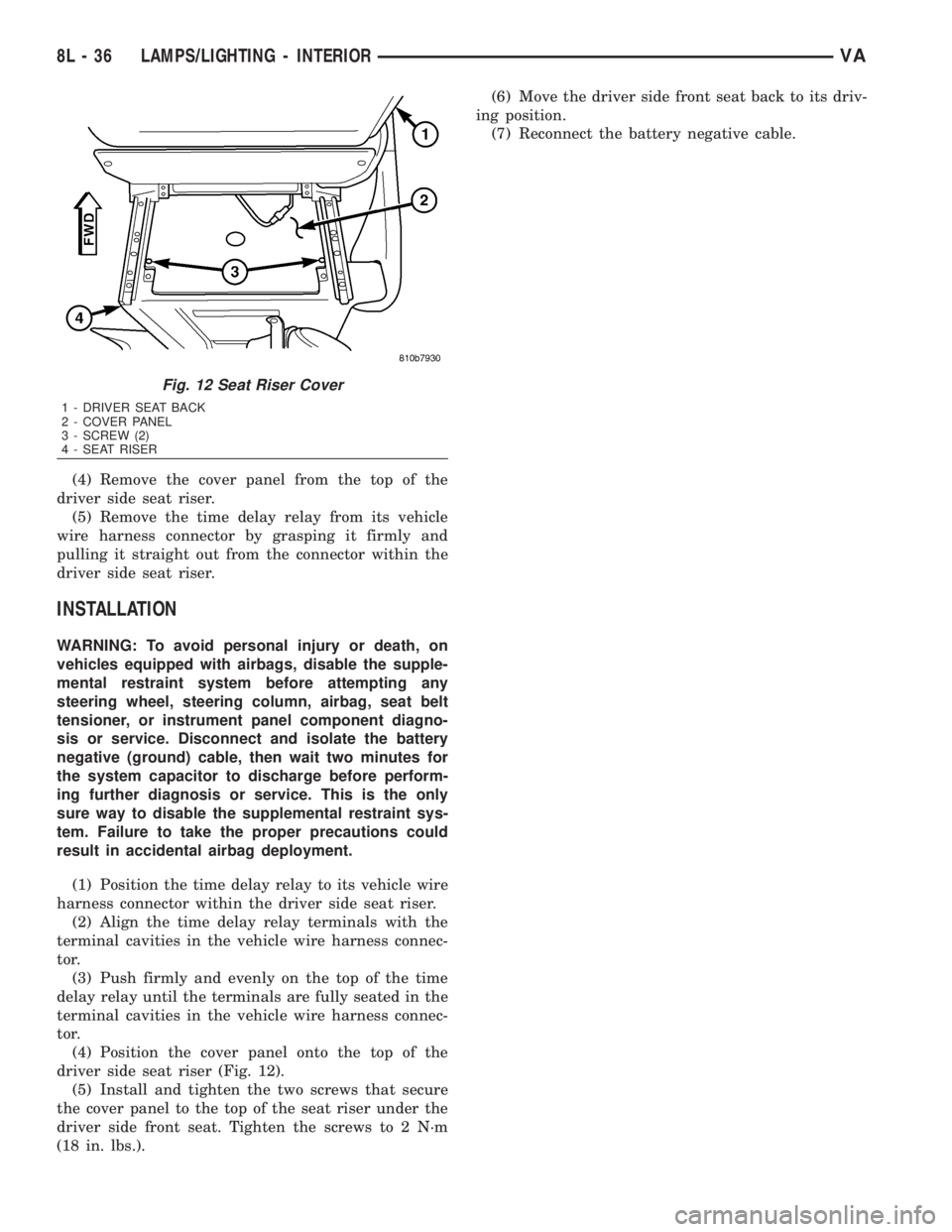
(4) Remove the cover panel from the top of the
driver side seat riser.
(5) Remove the time delay relay from its vehicle
wire harness connector by grasping it firmly and
pulling it straight out from the connector within the
driver side seat riser.
INSTALLATION
WARNING: To avoid personal injury or death, on
vehicles equipped with airbags, disable the supple-
mental restraint system before attempting any
steering wheel, steering column, airbag, seat belt
tensioner, or instrument panel component diagno-
sis or service. Disconnect and isolate the battery
negative (ground) cable, then wait two minutes for
the system capacitor to discharge before perform-
ing further diagnosis or service. This is the only
sure way to disable the supplemental restraint sys-
tem. Failure to take the proper precautions could
result in accidental airbag deployment.
(1) Position the time delay relay to its vehicle wire
harness connector within the driver side seat riser.
(2) Align the time delay relay terminals with the
terminal cavities in the vehicle wire harness connec-
tor.
(3) Push firmly and evenly on the top of the time
delay relay until the terminals are fully seated in the
terminal cavities in the vehicle wire harness connec-
tor.
(4) Position the cover panel onto the top of the
driver side seat riser (Fig. 12).
(5) Install and tighten the two screws that secure
the cover panel to the top of the seat riser under the
driver side front seat. Tighten the screws to 2 N´m
(18 in. lbs.).(6) Move the driver side front seat back to its driv-
ing position.
(7) Reconnect the battery negative cable.
Fig. 12 Seat Riser Cover
1 - DRIVER SEAT BACK
2 - COVER PANEL
3 - SCREW (2)
4 - SEAT RISER
8L - 36 LAMPS/LIGHTING - INTERIORVA
Page 992 of 2305

RESTRAINTS
TABLE OF CONTENTS
page page
RESTRAINTS
DESCRIPTION..........................2
OPERATION............................4
WARNINGS - RESTRAINT SYSTEM..........5
DIAGNOSIS AND TESTING - SUPPLEMENTAL
RESTRAINT SYSTEM...................5
STANDARD PROCEDURE
STANDARD PROCEDURE - HANDLING
NON-DEPLOYED SUPPLEMENTAL
RESTRAINTS.........................6
STANDARD PROCEDURE - SERVICE
AFTER A SUPPLEMENTAL RESTRAINT
DEPLOYMENT.........................6
STANDARD PROCEDURE - VERIFICATION
TEST................................7
AIRBAG CONTROL MODULE
DESCRIPTION..........................8
OPERATION............................8
REMOVAL.............................10
INSTALLATION.........................11
CLOCKSPRING
DESCRIPTION.........................12
OPERATION...........................13
STANDARD PROCEDURE - CLOCKSPRING
CENTERING.........................13
REMOVAL.............................14
INSTALLATION.........................15
DRIVER AIRBAG
DESCRIPTION.........................16
OPERATION...........................17
REMOVAL.............................18
INSTALLATION.........................19
FRONT SEAT BELT & RETRACTOR
REMOVAL.............................20
INSTALLATION.........................22
FRONT SEAT BELT BUCKLE
REMOVAL.............................23
INSTALLATION.........................23PASSENGER AIRBAG
DESCRIPTION.........................24
OPERATION...........................24
REMOVAL.............................25
INSTALLATION.........................27
PASSENGER AIRBAG BRACKET
REMOVAL.............................27
INSTALLATION.........................28
REAR SEAT BELT & RETRACTOR
REMOVAL.............................28
INSTALLATION.........................30
REAR SEAT BELT BUCKLE
REMOVAL
REMOVAL - INBOARD..................30
REMOVAL - OUTBOARD................31
INSTALLATION
INSTALLATION - INBOARD..............31
INSTALLATION - OUTBOARD............31
SEAT BELT SWITCH
DESCRIPTION.........................31
OPERATION...........................32
SEAT BELT TENSIONER
DESCRIPTION.........................32
OPERATION...........................33
SEAT BELT TURNING LOOP ADJUSTER
REMOVAL.............................33
INSTALLATION.........................35
SIDE CURTAIN AIRBAG
DESCRIPTION.........................35
OPERATION...........................36
REMOVAL.............................36
INSTALLATION.........................38
SIDE IMPACT SENSOR
DESCRIPTION.........................39
OPERATION...........................39
REMOVAL.............................40
INSTALLATION.........................40
VARESTRAINTS 8O - 1
Page 993 of 2305

RESTRAINTS
DESCRIPTION
An occupant restraint system is standard factory-
installed safety equipment on this model. Available
occupant restraints for this model include both active
and passive types. Active restraints are those which
require the vehicle occupants to take some action to
employ, such as fastening a seat belt; while passive
restraints require no action by the vehicle occupants
to be employed (Fig. 1).ACTIVE RESTRAINTS
The active restraints for this model include:
²Front Seat Belts- Both outboard front seating
positions are equipped with three-point seat belt sys-
tems employing a lower B-pillar mounted inertia
latch-type retractors, height-adjustable upper B-pil-
lar mounted turning loops, travelling lower seat belt
anchors secured to the outboard seat tracks, and
Fig. 1 Supplemental Restraint System
1 - PASSENGER AIRBAG (OPTIONAL)
2 - SIDE IMPACT SENSOR (2 - WITH OPTIONAL SIDE CURTAIN AIRBAGS ONLY)
3 - DRIVER AIRBAG
4 - AIRBAG CONTROL MODULE
5 - SEAT BELT TENSIONER (DRIVER SIDE - STANDARD, PASSENGER SIDE - OPTIONAL WITH PASSENGER AIRBAG ONLY)
6 - SIDE CURTAIN AIRBAG (2 - OPTIONAL)
8O - 2 RESTRAINTSVA