2006 MERCEDES-BENZ SPRINTER airbag
[x] Cancel search: airbagPage 528 of 2305
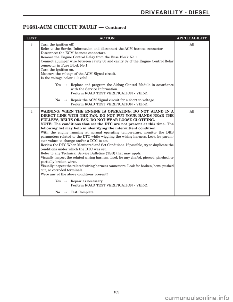
TEST ACTION APPLICABILITY
3 Turn the ignition off.
Refer to the Service Information and disconnect the ACM harness connector.
Disconnect the ECM harness connectors.
Remove the Engine Control Relay from the Fuse Block No.1
Connect a jumper wire between cavity 30 and cavity 87 of the Engine Control Relay
connector in Fuse Block No.1.
Turn the ignition on.
Measure the voltage of the ACM Signal circuit.
Is the voltage below 1.0 volt?All
Ye s!Replace and program the Airbag Control Module in accordance
with the Service Information.
Perform ROAD TEST VERIFICATION - VER-2.
No!Repair the ACM Signal circuit for a short to voltage.
Perform ROAD TEST VERIFICATION - VER-2.
4WARNING: WHEN THE ENGINE IS OPERATING, DO NOT STAND IN A
DIRECT LINE WITH THE FAN. DO NOT PUT YOUR HANDS NEAR THE
PULLEYS, BELTS OR FAN. DO NOT WEAR LOOSE CLOTHING.
NOTE: The conditions that set the DTC are not present at this time. The
following list may help in identifying the intermittent condition.
With the engine running at normal operating temperature, monitor the DRB
parameters related to the DTC while wiggling the wiring harness. Look for param-
eter values to change and/or a DTC to set.
Review the DTC When Monitored and Set Conditions. If possible, try to duplicate the
conditions under which the DTC was set.
Refer to any Technical Service Bulletins (TSB) that may apply.
Visually inspect the related wiring harness. Look for any chafed, pierced, pinched, or
partially broken wires.
Visually inspect the related wiring harness connectors. Look for broken, bent, pushed
out, or corroded terminals.
Were any of the above conditions present?All
Ye s!Repair as necessary.
Perform ROAD TEST VERIFICATION - VER-2.
No!Test Complete.
105
DRIVEABILITY - DIESEL
P1681-ACM CIRCUIT FAULT ÐContinued
Page 678 of 2305

9.0 CONNECTOR PINOUTS
ACCELERATOR PEDAL POSITION SENSOR (OBD)CAV CIRCUIT FUNCTION
1 18BL/DG ACCEL PEDAL POSITION SENSOR SIGNAL NO. 1
2 18BR/GY ACCEL PEDAL POSITION SENSOR GROUND NO. 2
3 18GY/DG ACCEL PEDAL POSITION SENSOR SIGNAL NO. 2
4 18BL/RD ACCEL PEDAL POSITION SENSOR 5 VOLT SUPPLY
5 18BR/BL ACCEL PEDAL POSITION SENSOR GROUND NO. 1
AIRBAG CONTROL MODULE - YELLOWCAV CIRCUIT FUNCTION
1 20BL DRIVER SEAT BELT TENSIONER LINE 2
2 20BR/YL DRIVER SEAT BELT TENSIONER LINE 1
3 20BL PASSENGER SEAT BELT TENSIONER LINE 2
4 20BR PASSENGER SEAT BELT TENSIONER LINE 1
5 20BK FUSED IGNITION SWITCH OUTPUT (RUN-START)
6 20BR GROUND
7 20YL AIRBAG WARNING INDICATOR DRIVER
8- -
9 20BK/RD K-ACM
10 20DG DRIVER AIRBAG SQUIB 1 LINE 2
11 20VT DRIVER AIRBAG SQUIB 1 LINE 1
12 - -
13 20BL/DG PASSENGER AIRBAG SQUIB 1 LINE 2
14 20BR/DG PASSENGER AIRBAG SQUIB 1 LINE 1
15 - -
16 - -
17 - -
18 - -
19 - -
20 20DG ENHANCED ACCIDENT REPORT DRIVER
21 -
22 -
23 -
24 -
25 -
BOOST PRESSURE SENSOR (OBD)CAV CIRCUIT FUNCTION
1 18BR/WT SENSOR GROUND
2 18WT/DG BOOST PRESSURE SENSOR SIGNAL
3 18WT/RD BOOST PRESSURE SENSOR 5 VOLT SUPPLY
C
O
N
N
E
C
T
O
R
P
I
N
O
U
T
S
255
CONNECTOR PINOUTS
Page 822 of 2305

The Steering Angle Sensor is used to measure rate/
speed and direction of the steering wheel. This sen-
sor has 4 wires 12V, ground and 2 CAN Bus circuits.
This sensor is wired directly to the CAN Bus. This
sensor has to be programmed using the DRB IIIt
(Fig. 5).
REMOVAL
(1) Disconnect the battery.
(2) Remove the airbag (Refer to 8 - ELECTRICAL/
RESTRAINTS/AIRBAG CONTROL MODULE -
REMOVAL).
(3) Remove the steering wheel (Refer to 19 -
STEERING/COLUMN/STEERING WHEEL -
REMOVAL).
(4) Remove the front cover (Fig. 6).
(5) Remove the upper and lower steering column
covers (Fig. 6).
(6) Remove the clockspring (Refer to 8 - ELECTRI-
CAL/RESTRAINTS/CLOCKSPRING - REMOVAL)
(Fig. 6).
(7) Disconnect the electrical connector from the
steering angle sensor (Fig. 6).
(8) Remove the steering angle sensor (Fig. 6).
INSTALLATION
NOTE: The installation position of the steering
angle sensor must have the plug connection at the
bottom (Fig. 6).
(1) Install the steering angle sensor to the column
(Fig. 6).(2) Reconnect the electrical connector to the steer-
ing angle sensor (Fig. 6).
(3) Install the clockspring (Refer to 8 - ELECTRI-
CAL/RESTRAINTS/CLOCKSPRING - INSTALLA-
TION) (Fig. 6).
(4) Install the upper and lower steering column
covers (Fig. 6).
(5) Install the front cover (Fig. 6).
(6) Install the steering wheel (Refer to 19 -
STEERING/COLUMN/STEERING WHEEL -
INSTALLATION).
(7) Install the airbag (Refer to 8 - ELECTRICAL/
RESTRAINTS/AIRBAG CONTROL MODULE -
INSTALLATION).
(8) Reconnect the battery.
(9) Recalibrate the steering angle sensor using the
scan tool.
LATERAL ACCELERATION
SENSOR
DESCRIPTION
The Yaw Rate and Lateral Acceleration Sensor is
housed into one unit (Fig. 7)(each individual sen-
sor can not be replaced separately the whole
housing unit must be replaced when servicing).
The sensor is used to measure side to side (Lateral)
motion and vehicle rotational sensing (how fast the
vehicle is turning). This is a 6±wire sensor with all
six wires connected to the ESP/ABS module.
REMOVAL
(1) Disconnect the battery.
(2) Move the drivers seat forward and upwards.
Fig. 6 STEERING ANGLE SENSOR
1 - UPPER STEERING COLUMN COVER
2 - CLOCKSPRING
3 - STEERING ANGLE SENSOR
4 - LOWER STEERING COLUMN COVER
5 - FRONT COVER
6 - STEERING ANGLE SENSOR ELECTRICAL CONNECTION
Fig. 7 YAW/LATERAL ACCELERATION SENSOR
1 - SEAT BOX
2 - YAW RATE/ LATERAL ACCELERATION SENSOR
VABRAKES - ABS 5 - 33
Page 855 of 2305

the status of the driver side front seat belt. This
audible warning occurs independent of the visual
warning provided by the EMIC ªSeatbeltº indicator.
²Lights-On Warning- The EMIC chime tone
generator will generate repetitive chime tones at a
fast rate when either front door is opened with the
ignition switch in any position except On, and the
exterior lights are turned On. The EMIC uses inter-
nal programming and hard wired inputs from the left
(lighting) control stalk of the multi-function switch,
the ignition switch, and both front door jamb
switches to determine the current status of these
switches. This chime will continue to sound until the
exterior lighting is turned Off, until the ignition
switch is turned to the On position, or until both
front doors are closed, whichever occurs first.
²Key-In-Ignition Warning- The EMIC chime
tone generator will generate repetitive chime tones at
a fast rate when the key is in the ignition lock cylin-
der, the ignition switch is in any position except On,
and either front door is opened. The EMIC uses
internal programming and hard wired inputs from
the key-in ignition switch, the ignition switch, and
both front door jamb switches to determine the cur-
rent status of these switches. The chime will con-
tinue to sound until the key is removed from the
ignition lock cylinder, until the ignition switch is
turned to the On position, or until both front doors
are closed, whichever occurs first.
²Audible Turn Signal/Hazard Warning Sup-
port- The EMIC contactless relay will generate
repetitive clicks at a slow rate during normal turn
signal/hazard warning operation, or at a fast rate
when a turn signal lamp bulb or circuit is inopera-
tive, in concert with the operation of the turn signal
indicators in the cluster. These clicks are designed to
emulate the sound of the opening and closing of the
contact points in a conventional electromechanical
turn signal or hazard warning flasher. The EMIC
uses a hard wired input received from the turn sig-
nal relay in the fuse block beneath the steering col-
umn through the turn signal or hazard warning
switch circuitry of the multi-function switch to deter-
mine when to flash the turn signal indicators and
activate the contactless relay on the cluster electronic
circuit board. The turn signal clicks will continue to
sound until the turn signal switch is turned Off, or
until the ignition switch is turned to the Off position,
whichever occurs first. The hazard warning clicks
will continue to sound until the hazard warning
switch is turned Off.
The EMIC provides chime service for all available
features in the chime warning system. The EMIC relies
upon its internal programming and hard wired inputs
from the front door ajar switches, the key-in ignition
switch, the ignition switch, the seat belt switch, and the
turn signal/hazard warning (multi-function) switches.
The EMIC relies upon electronic message inputsreceived from other electronic modules over the CAN
data bus network to provide chime service for the low
engine oil level warning. Upon receiving the proper
inputs, the EMIC activates the chime tone generator or
the contactless relay to provide the audible warning to
the vehicle operator. The internal programming of the
EMIC determines the priority of each chime request
input that is received, as well as the rate and duration
of each tone that is to be generated. See the owner's
manual in the vehicle glove box for more information on
the features provided by the chime warning system.
The hard wired chime warning system inputs to
the EMIC, as well as other hard wired circuits for
this system may be diagnosed and tested using con-
ventional diagnostic tools and procedures. However,
conventional diagnostic methods may not prove con-
clusive in the diagnosis of the EMIC, the CAN data
bus network, or the electronic message inputs used
by the EMIC to provide chime warning system ser-
vice. The most reliable, efficient, and accurate means
to diagnose the EMIC, the CAN data bus network,
and the electronic message inputs for the chime
warning system requires the use of a diagnostic scan
tool. Refer to the appropriate diagnostic information.
DIAGNOSIS AND TESTING - CHIME WARNING
SYSTEM
WARNING: To avoid personal injury or death, on
vehicles equipped with airbags, disable the supple-
mental restraint system before attempting any
steering wheel, steering column, airbag, seat belt
tensioner, or instrument panel component diagno-
sis or service. Disconnect and isolate the battery
negative (ground) cable, then wait two minutes for
the system capacitor to discharge before perform-
ing further diagnosis or service. This is the only
sure way to disable the supplemental restraint sys-
tem. Failure to take the proper precautions could
result in accidental airbag deployment.
The hard wired chime warning system inputs to
the ElectroMechanical Instrument Cluster (EMIC),
as well as other hard wired circuits for this system
may be diagnosed and tested using conventional
diagnostic tools and procedures. However, conven-
tional diagnostic methods may not prove conclusive
in the diagnosis of the EMIC, the Controller Area
Network (CAN) data bus network, or the electronic
message inputs used by the EMIC to provide chime
warning system service. The most reliable, efficient,
and accurate means to diagnose the EMIC, the CAN
data bus network, and the electronic message inputs
for the chime warning system requires the use of a
diagnostic scan tool. Refer to the appropriate diag-
nostic information.
8B - 2 CHIME/BUZZERVA
Page 857 of 2305
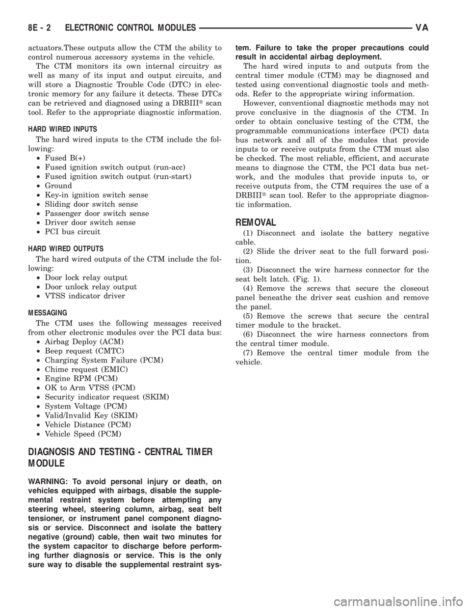
actuators.These outputs allow the CTM the ability to
control numerous accessory systems in the vehicle.
The CTM monitors its own internal circuitry as
well as many of its input and output circuits, and
will store a Diagnostic Trouble Code (DTC) in elec-
tronic memory for any failure it detects. These DTCs
can be retrieved and diagnosed using a DRBIIItscan
tool. Refer to the appropriate diagnostic information.
HARD WIRED INPUTS
The hard wired inputs to the CTM include the fol-
lowing:
²Fused B(+)
²Fused ignition switch output (run-acc)
²Fused ignition switch output (run-start)
²Ground
²Key-in ignition switch sense
²Sliding door switch sense
²Passenger door switch sense
²Driver door switch sense
²PCI bus circuit
HARD WIRED OUTPUTS
The hard wired outputs of the CTM include the fol-
lowing:
²Door lock relay output
²Door unlock relay output
²VTSS indicator driver
MESSAGING
The CTM uses the following messages received
from other electronic modules over the PCI data bus:
²Airbag Deploy (ACM)
²Beep request (CMTC)
²Charging System Failure (PCM)
²Chime request (EMIC)
²Engine RPM (PCM)
²OK to Arm VTSS (PCM)
²Security indicator request (SKIM)
²System Voltage (PCM)
²Valid/Invalid Key (SKIM)
²Vehicle Distance (PCM)
²Vehicle Speed (PCM)
DIAGNOSIS AND TESTING - CENTRAL TIMER
MODULE
WARNING: To avoid personal injury or death, on
vehicles equipped with airbags, disable the supple-
mental restraint system before attempting any
steering wheel, steering column, airbag, seat belt
tensioner, or instrument panel component diagno-
sis or service. Disconnect and isolate the battery
negative (ground) cable, then wait two minutes for
the system capacitor to discharge before perform-
ing further diagnosis or service. This is the only
sure way to disable the supplemental restraint sys-tem. Failure to take the proper precautions could
result in accidental airbag deployment.
The hard wired inputs to and outputs from the
central timer module (CTM) may be diagnosed and
tested using conventional diagnostic tools and meth-
ods. Refer to the appropriate wiring information.
However, conventional diagnostic methods may not
prove conclusive in the diagnosis of the CTM. In
order to obtain conclusive testing of the CTM, the
programmable communications interface (PCI) data
bus network and all of the modules that provide
inputs to or receive outputs from the CTM must also
be checked. The most reliable, efficient, and accurate
means to diagnose the CTM, the PCI data bus net-
work, and the modules that provide inputs to, or
receive outputs from, the CTM requires the use of a
DRBIIItscan tool. Refer to the appropriate diagnos-
tic information.
REMOVAL
(1) Disconnect and isolate the battery negative
cable.
(2) Slide the driver seat to the full forward posi-
tion.
(3) Disconnect the wire harness connector for the
seat belt latch. (Fig. 1).
(4) Remove the screws that secure the closeout
panel beneathe the driver seat cushion and remove
the panel.
(5) Remove the screws that secure the central
timer module to the bracket.
(6) Disconnect the wire harness connectors from
the central timer module.
(7) Remove the central timer module from the
vehicle.
8E - 2 ELECTRONIC CONTROL MODULESVA
Page 895 of 2305
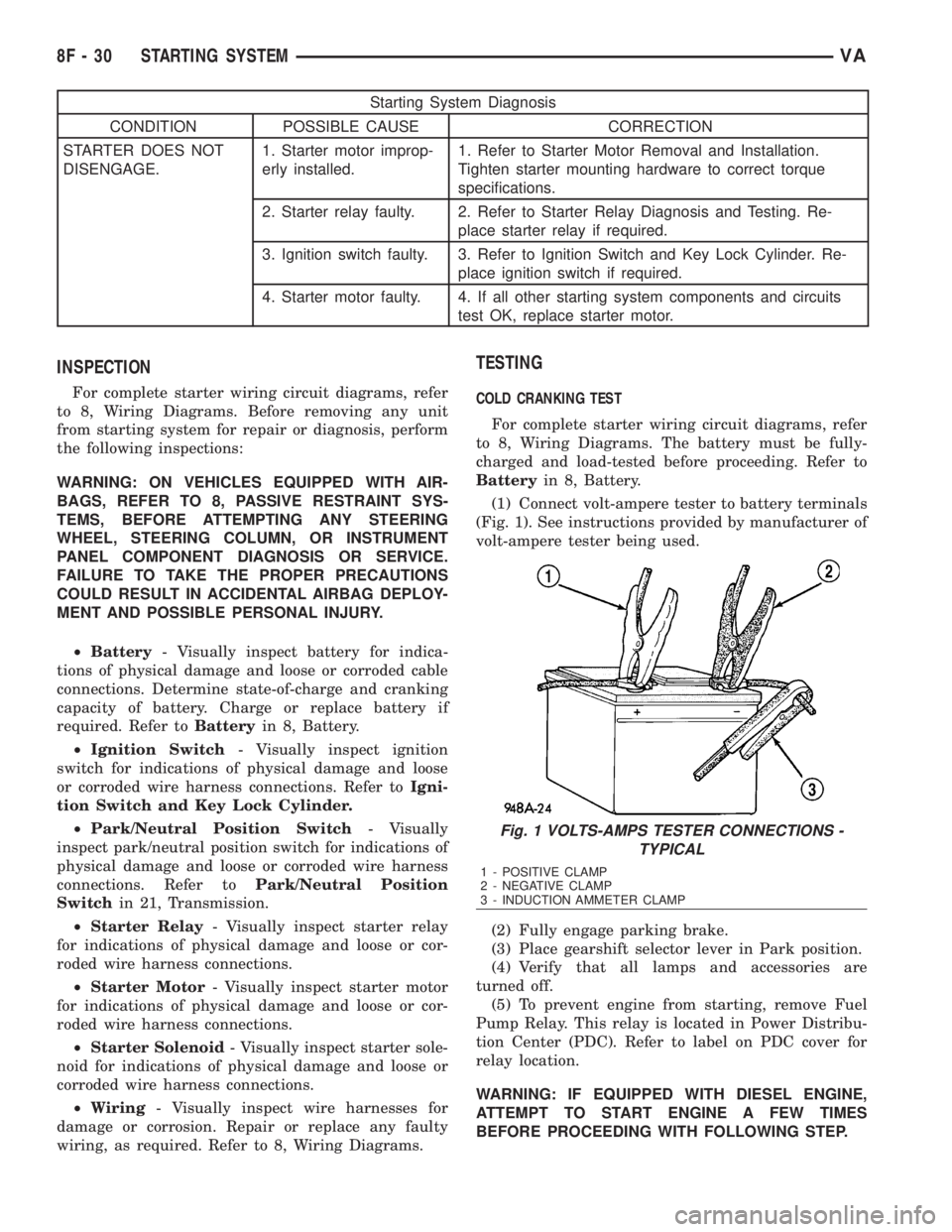
Starting System Diagnosis
CONDITION POSSIBLE CAUSE CORRECTION
STARTER DOES NOT
DISENGAGE.1. Starter motor improp-
erly installed.1. Refer to Starter Motor Removal and Installation.
Tighten starter mounting hardware to correct torque
specifications.
2. Starter relay faulty. 2. Refer to Starter Relay Diagnosis and Testing. Re-
place starter relay if required.
3. Ignition switch faulty. 3. Refer to Ignition Switch and Key Lock Cylinder. Re-
place ignition switch if required.
4. Starter motor faulty. 4. If all other starting system components and circuits
test OK, replace starter motor.
INSPECTION
For complete starter wiring circuit diagrams, refer
to 8, Wiring Diagrams. Before removing any unit
from starting system for repair or diagnosis, perform
the following inspections:
WARNING: ON VEHICLES EQUIPPED WITH AIR-
BAGS, REFER TO 8, PASSIVE RESTRAINT SYS-
TEMS, BEFORE ATTEMPTING ANY STEERING
WHEEL, STEERING COLUMN, OR INSTRUMENT
PANEL COMPONENT DIAGNOSIS OR SERVICE.
FAILURE TO TAKE THE PROPER PRECAUTIONS
COULD RESULT IN ACCIDENTAL AIRBAG DEPLOY-
MENT AND POSSIBLE PERSONAL INJURY.
²Battery- Visually inspect battery for indica-
tions of physical damage and loose or corroded cable
connections. Determine state-of-charge and cranking
capacity of battery. Charge or replace battery if
required. Refer toBatteryin 8, Battery.
²Ignition Switch- Visually inspect ignition
switch for indications of physical damage and loose
or corroded wire harness connections. Refer toIgni-
tion Switch and Key Lock Cylinder.
²Park/Neutral Position Switch- Visually
inspect park/neutral position switch for indications of
physical damage and loose or corroded wire harness
connections. Refer toPark/Neutral Position
Switchin 21, Transmission.
²Starter Relay- Visually inspect starter relay
for indications of physical damage and loose or cor-
roded wire harness connections.
²Starter Motor- Visually inspect starter motor
for indications of physical damage and loose or cor-
roded wire harness connections.
²Starter Solenoid- Visually inspect starter sole-
noid for indications of physical damage and loose or
corroded wire harness connections.
²Wiring- Visually inspect wire harnesses for
damage or corrosion. Repair or replace any faulty
wiring, as required. Refer to 8, Wiring Diagrams.
TESTING
COLD CRANKING TEST
For complete starter wiring circuit diagrams, refer
to 8, Wiring Diagrams. The battery must be fully-
charged and load-tested before proceeding. Refer to
Batteryin 8, Battery.
(1) Connect volt-ampere tester to battery terminals
(Fig. 1). See instructions provided by manufacturer of
volt-ampere tester being used.
(2) Fully engage parking brake.
(3) Place gearshift selector lever in Park position.
(4) Verify that all lamps and accessories are
turned off.
(5) To prevent engine from starting, remove Fuel
Pump Relay. This relay is located in Power Distribu-
tion Center (PDC). Refer to label on PDC cover for
relay location.
WARNING: IF EQUIPPED WITH DIESEL ENGINE,
ATTEMPT TO START ENGINE A FEW TIMES
BEFORE PROCEEDING WITH FOLLOWING STEP.
Fig. 1 VOLTS-AMPS TESTER CONNECTIONS -
TYPICAL
1 - POSITIVE CLAMP
2 - NEGATIVE CLAMP
3 - INDUCTION AMMETER CLAMP
8F - 30 STARTING SYSTEMVA
Page 906 of 2305
energizes the timing circuit of the rear window defog-
ger module which then activates the rear window
defogger (EBL) relays. The EBL relays controls the
current flow to the rear window defogger grids. The
EBL system will operate for approximately five min-
utes or until the rear window defogger switch or igni-
tion switch is turned off. Refer to 8 - ELECTRICAL/
HEATED GLASS - DIAGNOSIS AND TESTING for
diagnosis and testing of the rear window defogger
switch.
The rear window defogger switch cannot be
repaired and, if faulty or damaged, it must be
replaced.
DIAGNOSIS AND TESTING
REAR WINDOW DEFOGGER SWITCH
WARNING: On vehicles equipped with airbags, dis-
able the airbag system before attempting any steer-
ing wheel, steering column, or instrument panel
component diagnosis or service. Disconnect and
isolate the battery negative (ground) cable, then
wait two minutes for the airbag system capacitor to
discharge before performing further diagnosis or
service. This is the only sure way to disable the air-
bag system. Failure to take the proper precautions
could result in an accidental airbag deployment and
possible personal injury.
NOTE: The rear window defogger switch may be
tested in the vehicle or out of the vehicle, on a
bench.
NOTE: For circuit descriptions and diagrams of the
rear window defogger system, refer to 8W - WIRING
DIAGRAM INFORMATION.
(1) Remove the rear window defogger switch from
the instrument panel, but leave the switch connected
(Refer to 8 - ELECTRICAL/HEATED GLASS/REAR
WINDOW DEFOGGER SWITCH - REMOVAL).
(2) Turn the ignition switch ON.
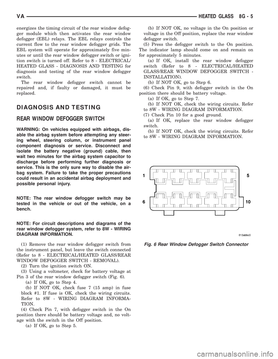
(3) Using a voltmeter, check for battery voltage at
Pin 3 of the rear window defogger switch (Fig. 6).
(a) If OK, go to Step 4.
(b) If NOT OK, check fuse 7 (15 amp) in fuse
block #1. If fuse is OK, check the wiring circuits.
Refer to 8W - WIRING DIAGRAM INFORMA-
TION.
(4) Check Pin 7, with defogger switch in the On
position there should be battery voltage and, no volt-
age with the switch in the Off position.
(a) If OK, go to Step 5.(b) If NOT OK, no voltage in the On position or
voltage in the Off position, replace the rear window
defogger switch.
(5) Press the defogger switch to the On position.
The indicator lamp should come on and remain on
for approximately 5 minutes.
(a) If OK, install the rear window defogger
switch (Refer to 8 - ELECTRICAL/HEATED
GLASS/REAR WINDOW DEFOGGER SWITCH -
INSTALLATION).
(b) If NOT OK, go to Step 6.
(6) Check Pin 9, with defogger switch in the On
position there should be battery voltage.
(a) If OK, go to Step 7.
(b) If NOT OK, check the wiring circuits. Refer
to 8W - WIRING DIAGRAM INFORMATION.
(7) Check Pin 10 for a good ground.
(a) If OK, replace the rear window defogger
switch.
(b) If NOT OK, check the wiring circuits. Refer
to 8W - WIRING DIAGRAM INFORMATION.
Fig. 6 Rear Window Defogger Switch Connector
VAHEATED GLASS 8G - 5
Page 907 of 2305
DEFOGGER SWITCH CONNECTOR PIN
CALL-OUT
PIN FUNCTION
1 FUSED B+ (DRL RELAY)
3 IGNITION SWITCH OUTPUT (START-
RUN)
5 PANEL LAMPS DRIVER
7 DEFOGGER SWITCH OUTPUT
9 PANEL LAMPS DRIVER
10 GROUND
REMOVAL
WARNING: To avoid personal injury or death, on
vehicles equipped with airbags, disable the supple-
mental restraint system before attempting any
steering wheel, steering column, airbag, seat belt
tensioner, or instrument panel component diagno-
sis or service. Disconnect and isolate the battery
negative (ground) cable, then wait two minutes for
the system capacitor to discharge before perform-
ing further diagnosis or service. This is the only
sure way to disable the supplemental restraint sys-
tem. Failure to take the proper precautions could
result in accidental airbag deployment.
(1) Disconnect and isolate the negative battery
cable.
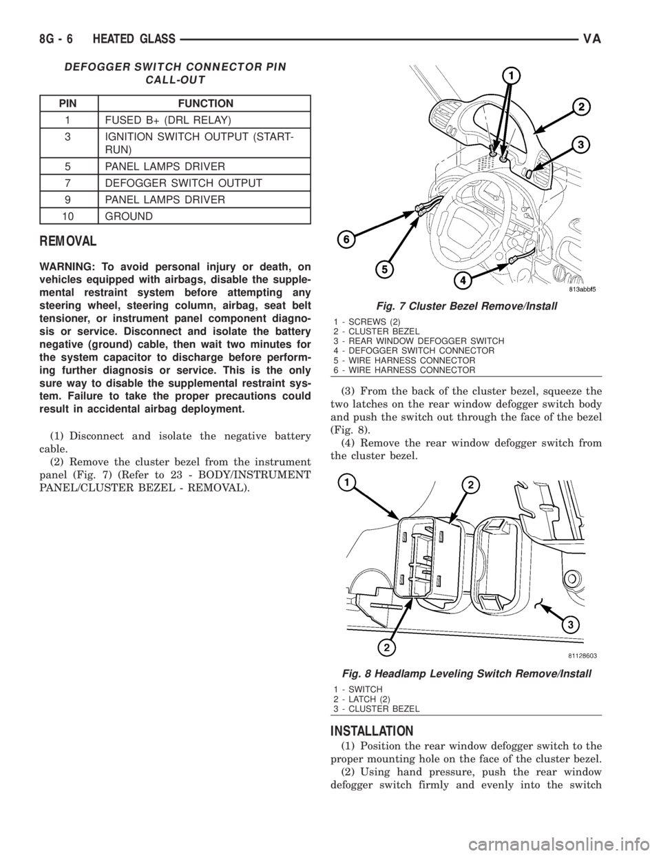
(2) Remove the cluster bezel from the instrument
panel (Fig. 7) (Refer to 23 - BODY/INSTRUMENT
PANEL/CLUSTER BEZEL - REMOVAL).(3) From the back of the cluster bezel, squeeze the
two latches on the rear window defogger switch body
and push the switch out through the face of the bezel
(Fig. 8).
(4) Remove the rear window defogger switch from
the cluster bezel.
INSTALLATION
(1) Position the rear window defogger switch to the
proper mounting hole on the face of the cluster bezel.
(2) Using hand pressure, push the rear window
defogger switch firmly and evenly into the switch
Fig. 7 Cluster Bezel Remove/Install
1 - SCREWS (2)
2 - CLUSTER BEZEL
3 - REAR WINDOW DEFOGGER SWITCH
4 - DEFOGGER SWITCH CONNECTOR
5 - WIRE HARNESS CONNECTOR
6 - WIRE HARNESS CONNECTOR
Fig. 8 Headlamp Leveling Switch Remove/Install
1 - SWITCH
2 - LATCH (2)
3 - CLUSTER BEZEL
8G - 6 HEATED GLASSVA