2006 LAND ROVER FRELANDER 2 Power Steering Hose
[x] Cancel search: Power Steering HosePage 44 of 3229
Publi s hed: 11-May-2011
General Information - Road/Roller Testing
Des cript ion and Operat ion
Road or roll ing road t es t ing may be carri ed out for various reasons and a procedure det ail ing pre-t es t checks , throughengi ne s tarti ng and s topping, pre-driving checks , on-t es t checks to final checks on complet ion of t he tes t are given.
Unles s complete vehi cl e performance is bei ng checked, t he ful l road t est procedure need not be carried out . Ins tead, t hos eit ems part icularly relevant t o t he s yst em(s) bei ng checked can be ext racted.
Pre-Test Checks
W ARNING: If t he brake s yst em hydraul ic fluid level i s l ow, pedal travel i s exces si ve or a hydraulic leak is found, donot att empt to road t est t he vehicle unt il t he reas on for t he low fl ui d l evel, excess ive pedal travel or hydraulic leak isfound and rect ified.
It is s ugges t ed that pre-t es t and funct ional t es ts of t hose sys tems/circuit s whi ch affect t he safe and l egal operati ons oft he vehi cl e, s uch as brakes , light s and s teeri ng, should al ways be carri ed out before the road or roll ing road tes t .
Engi ne oil l evelEngi ne cool ant levelTires, for correct pres sure, compat ible types and tread patt erns , and wear wi thi n limi ts .There i s s ufficient fuel in the t ank to compl ete the t est .Check al l around the engine, t rans mis s ion and under the vehicle for oil , coolant , hydraul ic and fuel l eaks . Make anote of any apparent leaks and wipe off t he surrounding areas t o make it easi er to identi fy t he extent of the leakon complet ion of t he tes t.
Starting the Engine
• NOTE: On i nit ial dri ve away from cold and wit hi n t he fi rs t 1.5 km (1 mile), do not depress accelerat or pedal beyond halft ravel unt il t he vehi cl e has att ained a minimum s peed of 25 km/h (15 mil es /h). Never operat e at high engi ne speed or wi tht he accelerat or pedal at ful l travel whil st the engine i s cold.
With the ignition off, check:
The parking brake is appli ed.Automatic transmission: The s el ect or lever is i n 'P' - PARK.Manual transmission: The gear l ever i s in NEUTRAL.All i ns t rument gauges read zero.
With the ignition on, check:
Igni ti on cont roll ed warni ng li ght s come on.Engi ne t emperature gauge regis t ers a readi ng compat ibl e wi th t he engine t emperat ure.Fuel gauge regi st ers a reading appropriate to the fuel l evel i n t he tank.The operati on of the parki ng brake warning l ight and fl ui d l evel warni ng indicator light.
On Road Test Check:
CAUTION: At commencement of road tes ti ng, check the brake operati on while s ti ll travel li ng at low speed beforecont inuing wit h t he tes t. If t he brakes pul l to one si de, or appear to be ot herwi se fault y, do not cont inue wit h t he roadt es t unti l the fault has been found and rect ified.
The parking brake releas es completel y.Gear changing i s s mooth, and t here are no abnormal noi s es or vi brati ons from t he t rans mis s ion.The engi ne power out put is s ati s factory, accel erati on is smoot h and accel erator pedal operat ion is not s ti ff orheavy, and engi ne s peed ret urns t o idl e correctl y.There i s no exces s ive or abnormall y colored s moke from t he engi ne under normal driving, heavy l oad or overruncondi ti ons .Steering operat ion i s s moot h, accurat e, not exces s ively heavy or wit h exces s ive free pl ay or vibrat ion. Does not pul lt o one s ide and s elf centres smoot hly after corneri ng.All i ns t rument s regis t er the correct readi ngs and operate correctl y.Swit ches and controls operat e s moothl y and posi ti vel y, warning or i ndi cat or light s operate correctl y and thedirect ion i ndi cat or cont rol s elf cancels when the s t eering i s ret urned t o t he s traight ahead pos it ion.Heati ng and vent il at ion sys tems work correct ly and effect ively.Brakes operate efficientl y.
Brake Testing
Avoi d brake t es ti ng on busy roads where i t can caus e i nconveni ence or danger t o ot her road users.
CAUTION: Brake t es ti ng which i ncludes heavy brake appl icati ons should not be carri ed out wit h new brake pads /dis csunti l the component s have bedded-i n. New brake fri ct ion component s wi ll not reach ful l efficiency unt il t he beddi ng-inprocess is complet e. Not e t hat when new parking brake shoes or rear brake di scs have been ins t al led, it i s es sent ial thatt he 'beddi ng-in' procedure i s carri ed out.For addit ional informat ion, refer t o: Parking Brake Shoes Bedding-In (206-05 Parking Brake and Actuati on, GeneralProcedures).
Test t he brakes at s everal speeds wit hin the normal operat ing range usi ng both light and heavy pedal pres s ure. Note anyt endency to snat ch, pull or drag, and any undue del ay in appli cat ion or release.
Page 536 of 3229
Publi s hed: 11-May-2011
Power Steering - Power Steering
Des cript ion and Operat ion
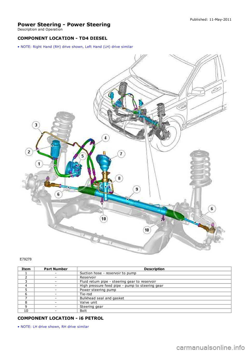
COMPONENT LOCATION - TD4 DIESEL
• NOTE: Right Hand (RH) drive shown, Left Hand (LH) drive s imil ar
ItemPart NumberDescription1-Sucti on hose - res ervoir t o pump
2-Res ervoir
3-Fl ui d ret urn pipe - s t eering gear to res ervoir4-Hi gh pres s ure feed pipe - pump to s t eering gear
5-Power s teeri ng pump
6-Ti e-rod7-Bul khead s eal and gas ket
8-Val ve uni t
9-St eering gear10-Bol t
COMPONENT LOCATION - i6 PETROL
• NOTE: LH drive s hown, RH dri ve si mi lar
Page 540 of 3229
diamet er in i ts central sect ion. The smal ler diamet er allows the t ors ion bar t o t wist in res pons e t o t orque appli ed from t hes teeri ng wheel in relati on t o t he grip of the t yres on t he road surface. The pi nion s haft has machined t eet h on it s cent raldiamet er whi ch mat e wit h t eeth on the s t eering gear rack. A s lot , machi ned in t he upper end of t he pini on s haft mateswit h t he dog-t oot h on the i nput s haft . The pinion s haft l ocat es in the pi ni on housi ng and rot ates on bal l and roll erbearings .
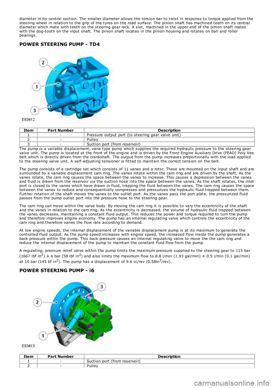
POWER STEERING PUMP - TD4
ItemPart NumberDescription1-Pres s ure out put port (t o s t eering gear val ve unit )
2-Pull ey
3-Sucti on port (from res ervoi r)The pump i s a vari abl e dis placement, vane t ype pump which s uppl ies t he required hydraulic pres sure t o the st eeri ng gearvalve unit . The pump is locat ed at t he front of t he engine and i s dri ven by the Front Engine Auxil iary Dri ve (FEAD) Poly Veebelt which i s direct ly driven from the cranks haft . The out put from t he pump i ncreas es proporti onall y wi th the l oad appl iedt o the st eeri ng val ve uni t. A s el f-adjus ti ng tens ioner is fit t ed to maint ai n t he correct t ens ion on the bel t.
The pump consi st s of a cart ridge s et which cons is t s of 11 vanes and a rot or. These are mount ed on t he input s haft and ares urrounded by a variable di spl acement cam ring. The vanes rotat e wit hin the cam ri ng and are driven by t he s haft. As thevanes rotat e, the cam ri ng caus es the space between t he vanes to increase. This causes a depres si on between t he vanesand fl uid i s drawn from t he res ervoir vi a t he suct ion hos e int o t he s pace between the vanes. As t he s haft rotat es , t he inl etport i s clos ed to the vanes which have drawn in fluid, t rapping t he fluid bet ween t he vanes . The cam ring caus es t he s pacebetween t he vanes to reduce and cons equenti ally compress es and pres s uri zes t he hydrauli c fl ui d t rapped between t hem.Furt her rotat ion of t he s haft moves the vanes t o the out let port . As t he vanes pas s t he port plat e, the pres s uri zed fl ui dpass es from the pump out let port into the press ure hose to the s t eering gear.
The cam ring can move wi thi n t he val ve body. By moving the cam ri ng it i s poss ibl e to vary t he eccentricit y of t he s haftand t he vanes i n rel ati on to the cam ri ng. As t he eccent rici ty i s decreased, t he volume of hydraulic flui d t rapped bet weent he vanes decreases , mai nt aining a cons t ant flui d output. This reduces t he power and torque required to turn t he pumpand t herefore improves engine economy. The pump has an int ernal regulati ng valve which controls t he eccentricit y of t hecam ring and t herefore vari es the flow rat e accordi ng to demand.
At low engi ne s peeds , the i nternal dis placement of the vari able di spl acement pump i s at it s maximum t o generate thecont rol led fluid out put. As t he pump s peed increas es wit h engine s peed, t he i ncreas ed flow ins ide t he pump generates aback press ure wit hin the pump. This back pres s ure causes an internal regul ati ng val ve to move t he the cam ri ng andreduce t he int ernal di spl acement of the pump to maint ian t he cons t ant flui d fl ow from the pump.
A regul ati ng, pres s ure reli ef val ve wit hin t he pump l imi ts the maxi mum press ure s uppl ied t o t he s teeri ng gear t o 115 bar
(1667 l bf in2) ± 4 bar (58 lbf i n2) and al so li mit s t he maximum fl ow t o 8.8 l/min (1.93 gal/min) ± 0.5 l /min (0.1 gal /min)
at 10 bar (145 bf i n2). The pump has a dis placement of 9.6 cc/rev (0.58i n3/rev).
POWER STEERING PUMP - i6
ItemPart NumberDescription
1-Sucti on port (from res ervoi r)
2-Pull ey
Page 2911 of 3229
191
Wheels and tyres
R
12. During the inflation, switch the
compressor off briefly to check the tyre
pressure using the gauge mounted on the
compressor.
• It should not take longer than seven
minutes to inflate the tyre. If after seven
minutes the tyre ha s not reached the
minimum pressure, the tyre should not
be used.
13. Once the tyre has been inflated switch off
the compressor. If desired the engine may
be turned off after the compressor has
been turned off.
14. Remove the power connector from the
auxiliary power socket.
15. Remove the inflation hose from the tyre
valve by unscrewing it as quickly as
possible (anti-clockwise).
16. Replace the inflation hose protective cap,
and the tyre valve cap.
17. Do not remove the sealant bottle from the
receiver.
18. Ensure that the tyre repair kit (including
the bottle, and receiver caps) are placed
securely in the vehicle. You will need to
use the kit to check the tyre pressure after
3km (2 miles) so ensure they are easily
accessible.
19. Immediately drive the vehicle for 3 km (2
miles) to allow the sealant to coat the inner
surface of the tyre and form a seal at the
puncture.
†When pumping the sealant through the tyre
valve, the pressure may rise up to 6 bar (87
lb/in²). The pressure will drop again after
approximately 30 seconds.
Checking the tyre pressure after a repair
1. Drive the vehicle for 3 km (2 miles) then
stop in a safe place. Carry out a visual
examination of the tyres condition.
2. Remove the protective cap from the
inflation hose.
3. Screw the inflation hos e connector firmly
onto the tyre valve.
4. Read the tyre pressure from the gauge.
5. If the pressure of the sealant filled tyre is
above 1.3 bar (19 lb/in²) adjust the
pressure to the correct value. See
TECHNICAL SPECIFICATIONS (page 194).
6. Ensure that the compressor switch is in
the off position ( O), and insert the power
cable connector into an auxiliary power
socket. See AUXILIARY POWER
SOCKETS (page 110).
7. If the vehicle is in a well ventilated area,
start the engine.
8. Switch on the compressor ( I), and inflate
the tyre to the correct pressure.
WARNINGS
When driving the vehicle, if you
experience vibr ations, abnormal
steering, or noises, re duce speed immediately.
Drive with extreme caution and reduced speed
to the first safe place to stop the vehicle.
Visually examine the tyre, and check it's
pressure. If there are any signs of damage or
deformity to the tyre, or the tyre pressure is
below 1.3 bar (19 lb/i n²) do not continue
driving.
Consult a tyre repair centre, or your
Land Rover Dealer/Authorised repairer
for advice concerning the replacement of a
tyre after using a tyre repair kit.