2006 LAND ROVER FRELANDER 2 torque
[x] Cancel search: torquePage 2715 of 3229
1. CAUTION: Make sure that new bolts are installed.
Clean the component mating faces.
With assistance, install the subframe.With assistance, align and secure the differential.Tighten the rear bolts.
Torque: 110 Nm
Tighten the front bolts.
Torque: 175 Nm
1.
2.
CAUTION: Make sure that new bolts are installed.
Align the suspension arms to the subframe and install the bolts, do
not fully tighten at this stage. 2.
Using the special tool, support the subframe. 3.
Connect the transmission breather lines. 4.
5. CAUTIONS:
Make sure that no components catch.
Make sure that new bolts are installed.
With assistance, position the subframe to the body and tighten the
bolts.
Torque: 175 Nm
5.
6.
CAUTION: Make sure that new bolts are installed.
Install the stabilizer clamp bolts, but do not tighten fully at this
stage. 6.
Connect the Active On-demand Coupling module electrical connector. 7.
Re mo ve t he p o we rt ra i n j a ck.
General Equi pment : P o w e rt ra i n Ja ck
8.
9.
CAUTION: Make sure that new bolts are installed.
Install the trailing arm to body brackets.
Torque: 110 Nm9.
10.
CAUTION: Make sure that the brake hose is not twisted
and is correctly located.
Clean the component mating faces.
Install the brake caliper anchor plate.
Torque: 110 Nm
Repeat the above procedure for the other side.
10.
Secure the wheel speed sensor and lead.
11.
Page 2716 of 3229
Torque: 5 NmSecure the lead in the clips.Repeat the above procedure for the other side.
LH side: Connect the ride height sensor electrical connector. 12.
Position and secure the rear shock absorbers.
Install both mass dampers.
Torque: 25 Nm
Repeat the above procedure for the other side.
13.
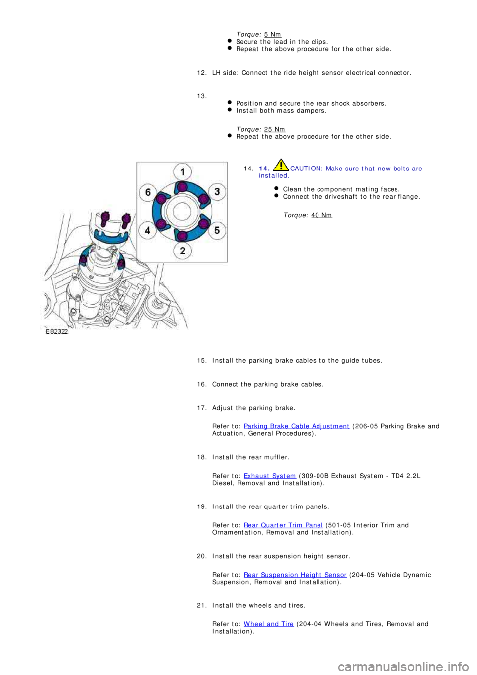
14. CAUTION: Make sure that new bolts are
installed.
Clean the component mating faces.
Connect the driveshaft to the rear flange.
Torque: 40 Nm
14.
Install the parking brake cables to the guide tubes. 15.
Connect the parking brake cables. 16.
Adjust the parking brake.
Refer to: Parking Brake Cable Adjustment
(206-05 Parki ng Brake and
Act uat i on, General Procedures ). 17.
Install the rear muffler.
Refer to: Exhaus t Sys t em
(309-00B Exhaus t Sys t em - TD4 2.2L
Diesel, Removal and Installation). 18.
Install the rear quarter trim panels.
Refer to: Rear Quarter Trim Panel
(501-05 Int eri or Tri m and
Ornament at i on, Removal and Ins t al lat i on). 19.
Install the rear suspension height sensor.
Refer to: Rear Suspension Height Sensor
(204-05 Vehi cl e Dynami c
Suspension, Removal and Installation). 20.
Install the wheels and tires.
Refer to: Wheel and Tire
(204-04 Wheels and Tires, Removal and
Installation). 21.
Page 2717 of 3229
22. CAUTION: Nuts and bolts must be tightened with the
weight of the vehicle on the suspension.
Tighten the stabilizer bar clamp bolts.
Torque: 60 Nm22.
23.
CAUTION: Nuts and bolts must be tightened with the
weight of the vehicle on the suspension.
Tighten the supsension arms to the subframe.
Torque: 175 Nm
During installation, do not tighten the nuts and bolts until
the 4 wheel alignment procedure has been carried out.
23.
Carry out a complete vehicle geometry check and adjustment. 24.
Page 2840 of 3229
Transmission
120
L
Sport mode and CommandShift™
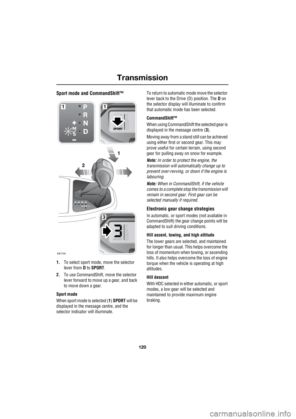
1. To select sport mode, move the selector
lever from D to SPORT .
2. To use CommandShift, move the selector
lever forward to move up a gear, and back
to move down a gear.
Sport mode
When sport mode is selected ( 1) SPORT will be
displayed in the message centre, and the
selector indicator will illuminate. To return to automatic m
ode move the selector
lever back to the Drive (D) position. The D on
the selector display will illuminate to confirm
that automatic mode has been selected.
CommandShift™
When using CommandShift th e selected gear is
displayed in the message centre ( 3).
Moving away from a stand still can be achieved
using either first or second gear. This may
prove useful for certai n terrain, using second
gear for pulling away on snow for example.
Note: In order to protect the engine, the
transmission will automatically change up to
prevent over-revving, or down if the engine is
labouring.
Note: When in CommandShift, if the vehicle
comes to a complete stop the transmission will
remain in second gear. First gear can be
selected manually if required.
Electronic gear change strategies
In automatic, or sport modes (not available in
CommandShift) the gear change points will be
adapted to suit driving conditions.
Hill ascent, towing, and high altitude
The lower gears are selected, and maintained
for longer than usual. This helps overcome the
loss of momentum when towing, or ascending
hills. It also helps over come the loss of engine
torque when the vehicle is operating at high
altitudes.
Hill descent
With HDC selected in either automatic, or sport
modes, a low gear will be selected and
maintained to provide maximum engine
braking.
2
1
1
3
1
E81744
Page 2856 of 3229

Hill descent control (HDC)
136
L
Hill descent control (HDC)PRINCIPLE OF OPERATION
HDC operates in conjunction with ABS to
provide greater control when off-road,
particularly when desc ending steep slopes.
HDC operation is fully automatic when
engaged.
During a hill descent when driving off-road,
engine braking is used to control the speed of
descent. If engine braki ng alone is insufficient
to control the vehicle's speed, HDC will slow
the vehicle using the braking system. HDC will
control the descent speed relative to the gear
selected and accelerator position.
If the vehicle is fitted with a manual
transmission, HDC should onl y be used in first,
or reverse gears. If the vehicle is fitted with an
automatic transmission, HDC should only be
used in D, R , or CommandShift 1. When in D
the vehicle will select the most appropriate
gear.
Note: HDC is automatically selected by some
of the Terrain response special programs.
Gradient release control (GRC)
With HDC activated, if the vehicle is stopped on
a slope using the footbrake, GRC will become
active. When the footbrake is released GRC will
automatically delay the brake release to allow
take up of drive, and build up of engine torque.
The brakes will then gradually release to allow
the vehicle to move smoothly away under the
control of HDC.
GRC operates in forwar d and reverse, and
requires no driver intervention.
Before driving off-road
Before venturing off-road it is absolutely
essential that inexperi enced drivers become
fully familiar with the vehicle's controls. In
particular, CommandShift , Hill Descent Control
(HDC), and the Terra in Response system.
Basic information and off-road driving
techniques can be found in the off-road driving
handbook available on-line at
http://www.ownerinfo.landrover.com
Off-road driver traini ng should be undertaken
by anyone intending to drive off-road. Training
is available at your nearest Land Rover
Experience centre. More details can be found at
http://www.landroverexperience.com
Page 2860 of 3229
Stability control
140
L
Stability controlPRINCIPLE OF OPERATION
Dynamic Stability Control (DSC)
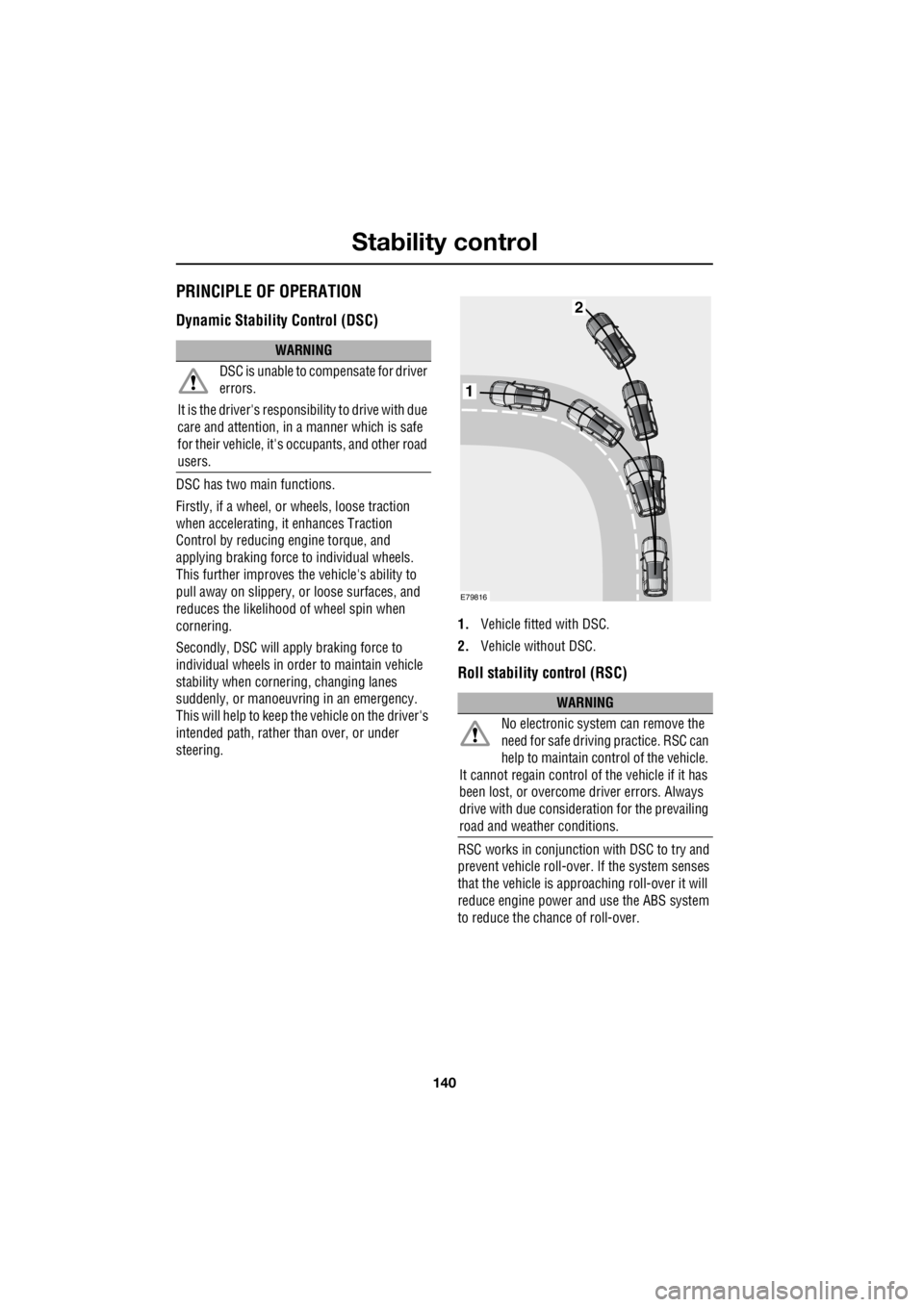
DSC has two main functions.
Firstly, if a wheel, or wheels, loose traction
when accelerating, it enhances Traction
Control by reducing engine torque, and
applying braking force to individual wheels.
This further improves the vehicle's ability to
pull away on slippery, or loose surfaces, and
reduces the likelihood of wheel spin when
cornering.
Secondly, DSC will apply braking force to
individual wheels in orde r to maintain vehicle
stability when cornering, changing lanes
suddenly, or manoeuvring in an emergency.
This will help to keep the vehicle on the driver's
intended path, rather than over, or under
steering. 1.
Vehicle fitted with DSC.
2. Vehicle without DSC.
Roll stability control (RSC)
RSC works in conjunction with DSC to try and
prevent vehicle roll-over. If the system senses
that the vehicle is approaching roll-over it will
reduce engine power and use the ABS system
to reduce the chance of roll-over.
WARNING
DSC is unable to compensate for driver
errors.
It is the driver's responsibility to drive with due
care and attention, in a manner which is safe
for their vehicle, it's oc cupants, and other road
users.
WARNING
No electronic system can remove the
need for safe drivin g practice. RSC can
help to maintain control of the vehicle.
It cannot regain control of the vehicle if it has
been lost, or overcome driver errors. Always
drive with due consideration for the prevailing
road and weather conditions.
1
2
E79816
Page 2905 of 3229
185
Wheels and tyres
R
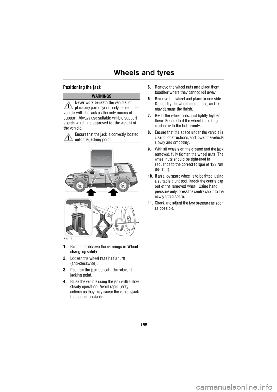
Positioning the jack
1. Read and observe the warnings in Wheel
changing safety .
2. Loosen the wheel nuts half a turn
(anti-clockwise).
3. Position the jack be neath the relevant
jacking point.
4. Raise the vehicle using the jack with a slow
steady operation. Avoid rapid, jerky
actions as they may cause the vehicle/jack
to become unstable. 5.
Remove the wheel nuts and place them
together where they cannot roll away.
6. Remove the wheel and place to one side.
Do not lay the wheel on it's face, as this
may damage the finish.
7. Re-fit the wheel nuts, and lightly tighten
them. Ensure that the wheel is making
contact with the hub evenly.
8. Ensure that the space under the vehicle is
clear of obstructions, and lower the vehicle
slowly and smoothly.
9. With all wheels on the ground and the jack
removed, fully tighte n the wheel nuts. The
wheel nuts should be tightened in
sequence to the correct torque of 133 Nm
(98 lb.ft).
10. If an alloy spare wheel is to be fitted, using
a suitable blunt tool, knock the centre cap
out of the removed wheel. Using hand
pressure only, press the centre cap into the
newly fitted spare.
11. Check and adjust the tyre pressure as soon
as possible.
WARNINGS
Never work beneath the vehicle, or
place any part of yo ur body beneath the
vehicle with the jack as the only means of
support. Always use su itable vehicle support
stands which are approved for the weight of
the vehicle.
Ensure that the jack is correctly located
onto the jacking point.
E80178
Page 2906 of 3229
Wheels and tyres
186
L
Wheel nut tightening sequence
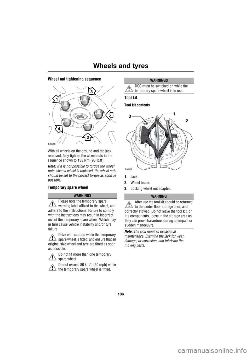
With all wheels on the ground and the jack
removed, fully tighten the wheel nuts in the
sequence shown to 133 Nm (98 lb.ft).
Note: If it is not possible to torque the wheel
nuts when a wheel is replaced, the wheel nuts
should be set to the correct torque as soon as
possible.
Temporary spare wheel Tool kit
Tool kit contents
1.
Jack.
2. Wheel brace.
3. Locking wheel nut adapter.
Note: The jack requi res occasional
maintenance. Examine the jack for wear,
damage, or corrosion, and lubricate the
moving parts.
WARNINGS
Please note the temporary spare
warning label affixed to the wheel, and
adhere to the instructions. Failure to comply
with the instructions may result in incorrect
use of the temporary spare wheel. Which may
in turn cause vehicle instability and/or tyre
failure.
Drive with caution while the temporary
spare wheel is fitted, and ensure that an
original size wheel and tyre are fitted as soon
as possible.
Do not fit more than one temporary
spare wheel.
Do not exceed 80 km/h (50 mph) while
the temporary spare wheel is fitted.
E83968
5
1
3
2
4
DSC must be switched on while the
temporary spare wheel is in use.
WARNING
After use the tool kit should be returned
to the under floor storage area, and
correctly stowed. Do not leave the tool kit, or
it's components, loose in the storage area as
they can prove hazardous during an impact or
sudden manoeuvre.
WARNINGS
3
E80162
1
2