2006 LAND ROVER FRELANDER 2 washer fluid
[x] Cancel search: washer fluidPage 1491 of 3229
Publi s hed: 11-May-2011
Transfer Case - Transfer Case Fluid Level Check
General Procedures CAUTION: The fluid fi ller plug is not a flui d level pl ug.
1. W ARNING: Make sure t o s upport the vehicle wit h axle
s tands .
Rais e t he vehicle on a li ft .
1.
Remove t he engi ne undershi eld.
Refer t o: Engi ne Unders hi eld (501-02 Front End Body Panel s ,
Removal and Ins tall ati on).
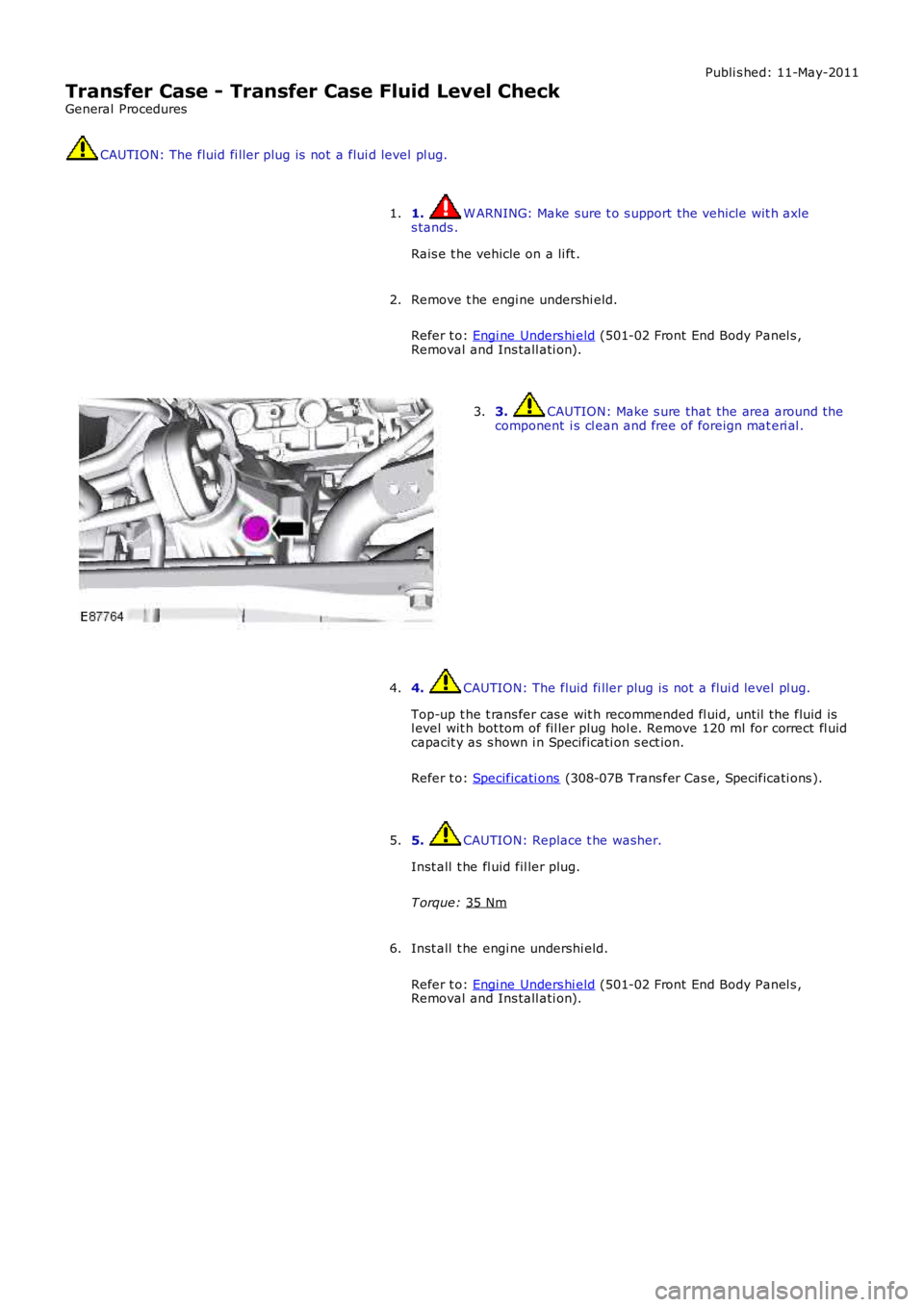
2. 3. CAUTION: Make s ure that the area around t he
component i s cl ean and free of foreign mat eri al .
3.
4. CAUTION: The fluid fi ller plug is not a flui d level pl ug.
Top-up t he t rans fer cas e wit h recommended fl uid, unti l the fluid is
l evel wit h bot tom of fil ler plug hol e. Remove 120 ml for correct fl uid
capacit y as s hown i n Specificati on s ect ion.
Refer t o: Specificati ons (308-07B Trans fer Cas e, Specificati ons ).
4.
5. CAUTION: Replace t he washer.
Inst all t he fl uid fil ler plug.
T orque: 35 Nm 5.
Inst all t he engi ne undershi eld.
Refer t o: Engi ne Unders hi eld (501-02 Front End Body Panel s ,
Removal and Ins tall ati on).
6.
Page 1772 of 3229
il lumi nat ed for t he remaining 2 s econds of the bulb check, this indicates t hat faults are st ored in t he ABS module memory.
If the warning i ndi cat or was il luminat ed due to a wheel speed s ensor faul t, t he i ndicat or will remain ill uminat ed at thenext i gnit ion cycl e, even i f the fault is recti fi ed. W hen the vehicle is driven above a s peed of 20 km/h (12.5 mph) theindicat or wi ll be ext ingui s hed. This al lows t he ABS module to perform a thorough check of t he s yst em and to es t abl is h t hatt he out put from t he repl aced s ensor i s correct .
Low Fuel Level Indicator
The low fuel level indicator is cont roll ed by t he fuel level gage s oftware (s ee above). W hen t he vehicle ent ers power mode6, the low fuel i ndicat or is ill uminat ed in an amber color for a 3 s econd bulb check. If t he fuel level gage softwaredetermines t he low fuel indicator s houl d be i ll uminated, it flas hes t he indicator at a rate of 2 Hz for 5 seconds . The firstfl ash is accompani ed by a chime from t he ins t rument clus ter s ounder. After t he 5 s econd fl as hing period t he indi cat or willremai n i llumi nated unt il fuel is added t o t he t ank or t he vehi cle i gni ti on is swi tched off.
Parking Brake Indicator
The red parking brake i ndi cat or is i ll uminated on receipt of a medium s peed CAN bus s ignal from t he CJB. The s ignalori ginates i n t he parking brake micros wit ch, whi ch is hardwired to the CJB. The parking brake indicator wil l onl y i llumi nateif t he parking brake is appli ed and t he vehi cl e is in power mode 6.
Rear Fog Lamp Indicator
The rear fog lamp indicator is il luminat ed on receipt of a medi um s peed CAN bus s ignal from t he CJB. The i ndicat or isil lumi nat ed i n an amber col or if t he vehi cl e is in power mode 6 and rear fog l amp operat ion has been reques ted.
Front Fog Lamp Indicator
The front fog l amp i ndi cat or is i ll uminated on recei pt of a medium s peed CAN bus si gnal from the CJB. The indi cat or i sil lumi nat ed i n a green color i f the vehicle is i n power mode 6 and front fog lamp operat ion has been reques ted.
Adaptive Front Lighting System Indicator
The Adapt ive Front l ight ing Syst em (AFS) indicator i s cont rol led by t he AFS module. The AFS module i s hardwi red t o t heCJB, whi ch relays s ignals to the i nst rument clus ter over the medi um s peed CAN bus . When t he vehi cl e enters power mode6, the AFS indicator is ill uminat ed in an amber color for a 3 s econd bul b check. If duri ng AFS operati on a faul t is det ect ed,t he AFS indicator wi ll fl ash at a frequency of 2 Hz.
Speed Control Indicator
The s peed control indicator i s cont roll ed by t he ECM, which t rans mit s a s peed cont rol acti ve si gnal t o t he ins t rumentclus ter via the CJB. The indicator wi ll il lumi nat e i n an amber col or when the vehicle is i n power mode 6 and s peed cont rolis act ive.
Trailer Indicator
The t rail er indicator is cont roll ed by t he ins trument cl ust er on receipt of medium speed CAN bus si gnal s from the CJB.W hen a trailer i s connected t o t he vehi cle el ect ri cal s ys t em and t he t urn s i gnal indicat or s wi tch i s operated, t he CJBt ransmit s a s ignal to the ins trument cl us t er to operat e t he t rail er indicator. The inst rument clus t er s oftware cont rol s thefl ash rat e of the indicator which flas hes in a green color. The t rai ler indi cat or flas hes s lowly, at t he s ame rat e as t he t urns ignal indicators .
Low Washer Fluid Indicator
The low washer fluid indicator is il luminat ed on receipt of a medi um s peed CAN bus signal from t he CJB. The s i gnalori ginates i n t he low washer fl uid l evel s wit ch, whi ch is hardwired to the CJB.
The amber low was her fl uid i ndi cat or is s ubject t o a 3 second bul b check when the vehicle ent ers power mode 6. If a lowwas her fluid level is detect ed for more t han 15 seconds when the vehicle is i n power mode 6, the ins trument cl us t er wil lil lumi nat e t he indi cat or.
Low Engine Coolant Level Warning Ind icator
The low engi ne cool ant l evel warni ng indicat or i s il lumi nat ed on recei pt of a medium speed CAN bus s i gnal from the CJBwhen t he vehi cl e is in power mode 6. The s ignal origi nat es in the ECM, whi ch trans mits the s i gnal t o t he CJB over t he highs peed CAN bus.
W hen t he vehicle ent ers power mode 6, the amber l ow engine coolant level warning i ndi cat or is i ll uminated for a 3 secondbulb check. If the warning i ndi cat or remai ns ill uminat ed aft er this period, the engine cooli ng s yst em s hould be checked forleaks and t opped up as necess ary.
Transmission Warning Indicator
The t ransmis s ion warni ng indi cat or di spl ays aut omati c transmis s ion and acti ve-on demand coupli ng warni ngs . The warni ngindicat or i s il lumi nat ed on recei pt of medi um s peed CAN bus s ignals from t he CJB. The s ignals origi nat e i n theTrans mis s ion Cont rol Modul e (TCM) and the act ive-on demand coupl ing control modul e res pect ively and are t rans mi tt ed tot he CJB over t he high s peed CAN bus .
The t ransmis s ion warni ng indi cat or i s a dual col or indicator, whi ch is subject t o a 3 second bulb check when the vehicleenters power mode 6. For t he fi rs t 1.5 seconds of the bulb check t he indicator i llumi nates i n an amber col or, fol lowed by1.5 seconds ill uminat ed in a red color.
The t abl e below det ails warning i ndicat or col or agai ns t mes s age cent er mess age.
Page 1789 of 3229
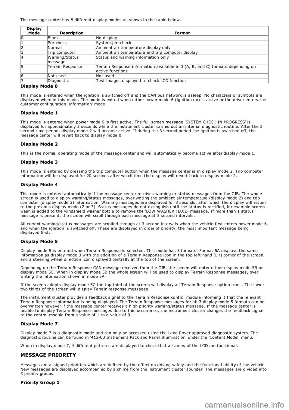
The mes s age center has 8 di fferent dis play modes as s hown i n the table bel ow.
DisplayModeDescriptionFormat0Bl ankNo dis play
1Pre-checkSys tem pre-check
2NormalAmbi ent ai r temperature dis play only3Trip computerAmbi ent ai r temperature and trip comput er di spl ay
4W arning/St atusmes s ageSt atus and warning i nformat ion onl y
5Terrain Res ponseTerrain Res ponse informat ion available in 3 (A, B, and C) format s depending onact ive functi ons6Not us edNot us ed
7Di agnos ti cTes t images di spl ayed t o check LCD functi on
Display Mode 0
This mode is entered when t he ignit ion i s s wit ched off and t he CAN bus network is asl eep. No characters or symbol s aredis played when in thi s mode. The mode is exi ted when ei ther power mode 6 (ignit ion on) is act ive or t he dri ver enters t hecus t omer configurat ion 'Informati on' mode.
Display Mode 1
This mode is entered when power mode 6 i s fi rs t acti ve. The full s creen mes sage 'SY STEM CHECK IN PRO GRESS' isdis played for approximat ely 3 s econds whil e the ins trument cl us t er carri es out an internal di agnos ti c rout ine. Aft er t he 3s econd t ime period, dis play mode 2 wil l become act ive. If duri ng t he 3 s econd peri od t he ignit ion i s s wit ched off, t hemes s age center wi ll revert back t o dis play mode 0.
Display Mode 2
This i s t he normal operati ng mode of t he mes sage center and wi ll automat ically become acti ve aft er dis play mode 1.
Display Mode 3
This mode is entered by pres s ing t he t ri p comput er but t on when the mess age cent er is in di spl ay mode 2. Trip comput erinformat ion wi ll be di spl ayed for 20 s econds aft er whi ch ti me t he dis play will revert back t o di spl ay mode 2.
Display Mode 4
This mode is entered automat ically if t he mes sage center receives warning or s tat us mes sages from the CJB. The wholes creen is us ed t o dis play warning/s t atus mes s ages , over wri ti ng the ambi ent ai r temperat ure (di spl ay mode 2) and tripcomput er (di spl ay mode 3) informat ion. W arni ng mes sages are dis played for 3 seconds , aft er which t he dis play wi ll ret urnt o the previous dis play mode (2 or 3). St atus mess ages do not ext inguis h unt il t he st atus is rect ified, for example s creenwas h is added t o t he winds hield washer bott le to remove t he 'LOW W ASHER FLUID' mes s age. If more than 1 st atusmes s age is pres ent, t he s creen wi ll s croll t hrough each mes s age at 3 s econd i ntervals.
All current warning/s t atus mes s ages are s croll ed t hrough at 3 s econd i nt ervals when the vehicle fi rs t enters power mode 6,and when t he ignit ion i s s wit ched off. Thes e are dis played in order of priori ty, t he mos t important mes s age bei ngdis played fi rs t .
Display Mode 5
Dis play mode 5 is ent ered when Terrain Respons e is sel ect ed. This mode has 3 format s. Format 5A dis plays t he sameinformat ion as di spl ay mode 3 wi th the addit ion of a Terrai n Respons e icon i n t he top left hand (LH) corner of t he s creen,and a s t eering wheel direct ion i con di s pl ayed centrall y at the top of t he s creen.
Dependi ng on the Terrai n Respons e CAN mes s age received from the CJB, the screen will ent er ei ther dis play mode 5B ordis play mode 5C. W hen in di spl ay mode 5B t he whole screen will be us ed t o dis play Terrain Res ponse mes sages , overwrit ing t he informat ion s hown in mode 5A.
If the s creen adopts di spl ay mode 5C t he t op thi rd of t he s creen wil l dis play all Terrain Res pons e opt ion i cons . The lowert wo t hi rds of t he s creen wil l dis play Terrain respons e mes s ages .
The ins t rument clus ter provides a feedback s ignal to the Terrain Res ponse cont rol module i nforming i t that t he rel evantTerrai n Res pons e i nformat ion is being di s pl ayed. The Terrain Res pons e mes s ages for all 3 di s pl ay mode 5 format s can beoverwri tt en however i f the mess age cent er receives a hi gh priorit y warni ng/s tat us mes sage. If t he mes s age cent er isunabl e t o dis play Terrain Res ponse mess ages due t o thi s occurrence, t he ins trument cl ust er changes t he feedback s ignalt o the cont rol module from a value of 1 to a val ue of 0.
Display Mode 7
Dis play mode 7 is a diagnost ic mode and can onl y be acces s ed usi ng t he Land Rover approved di agnos ti c s yst em. Thediagnost ic routi ne can be found i n '413-00 Ins trument Pack and Panel Ill uminat ion' under the 'Cont ent Model ' menu.
W hen i n dis play mode 7, 4 different patt erns are dis played t o check t hat al l areas of the LCD are funct ional.
MESSAGE PRIORITY
Mes sages are ass i gned priori ti es which are defi ned by the effect on dri vi ng s afely and the funct ional abi li ty of t he vehi cl e.New mes s ages are di spl ayed accompani ed by a chime from t he ins t rument clus ter s ounder. The mes s ages are di vi ded int o3 priori ty groups .
Priority Group 1
Page 2725 of 3229

Contents
5
R
ENGINE COOLANT CHECK ............................ 163
BRAKE AND CLUTCH FLUID CHECK ............. 165
POWER STEERING FLUID CHECK ................ 166
WASHER FLUID CHECK ................................ 167
TECHNICAL SPECIFICATIONS ...................... 169
Vehicle battery
BATTERY WARNING SYMBOLS ................... 171
BATTERY CARE ............................................ 171
USING BOOSTER CABLES ............................ 173
CHARGING THE VE HICLE BATTERY ............. 174
CHANGING THE VE HICLE BATTERY ............. 174
Wheels and tyres
GENERAL INFORMATION ............................. 176
TYRE CARE ................................................... 177
USING WINTER TYRES................................. 183
CHANGING A ROAD WHEEL ......................... 183
TYRE REPAIR KIT ......................................... 187
USING SNOW CHAINS.................................. 192
TYRE GLOSSARY.......................................... 193
TECHNICAL SPECIFICATIONS ...................... 194
Fuses
FUSE BOX LOCATIONS ................................. 195
CHANGING A FUSE ....................................... 195
FUSE SPECIFICATION CHART....................... 196
Emergency equipment
HAZARD WARNING FLASHERS .................... 204
WARNING TRIANGLE ................................... 204
Status after a collision
DRIVING AFTER A COLLISION...................... 205
INSPECTING SAFETY SYSTEM COMPONENTS ...
206
Vehicle recovery
TOWING POINTS .......................................... 207
LASHING POINTS ......................................... 208
TRANSPORTING THE VEHICLE..................... 208
TOWING THE VEHICLE ON FOUR WHEELS .. 208
Vehicle identification
VEHICLE IDENTIFICATION PLATE................. 210
VEHICLE IDENTIFI CATION NUMBER (VIN) ... 210
VEHICLE BUILD DATE PLATE ....................... 210
Technical specifications
ENGINE SPECIFICATIONS ............................ 211
WEIGHTS...................................................... 212
DIMENSIONS................................................ 213
Type approval
Declarations of conformity ........................... 215
Audio introduction
RADIO RECEPTION....................................... 218
Audio unit overview
AUDIO UNIT OVERVIEW............................... 219
Audio unit operation
ON OR OFF CONTROL .................................. 223
VOLUME CONTROL ...................................... 223
AUDIO CONTROL ......................................... 223
WAVEBAND BUTTON ................................... 224
AUTOSTORE CONTROL ................................ 225
STATION PRESET BUTTONS ........................ 226
TRAFFIC INFORMATION CONTROL .............. 226
Audio unit menus
RADIO DATA SYSTEM (RDS) ....................... 228
REGIONAL MODE (REG) .............................. 228
ENHANCED OTHER NETWORK (RDS-EON).. 229
ALTERNATIVE FREQUENCIES ...................... 229
NEWS BROADCASTS ................................... 230
PRIORITY PROGRAMME TYPE (PTY) .......... 231
RESETTING THE AUDIO UNIT ...................... 233
Digital audio broadcasting
GENERAL INFORMATION ............................. 234
AUDIO CONTROLS ....................................... 235
DISPLAY OPTIONS ....................................... 236
CHANNEL AUTOMATIC TUNING................... 236
CHANNEL OPTIONS ..................................... 236
PRESET BUTTONS ....................................... 238
SETTINGS..................................................... 240
Compact disc player
LOADING COMPACT DISCS ......................... 245
EJECTING COMPACT DISCS ........................ 246
EJECTING MULTIPLE CO MPACT DISCS....... 246
COMPACT DISC SELECTION ........................ 246
COMPACT DISC PLAYBACK ......................... 246
Page 2741 of 3229
21
Quick start
R
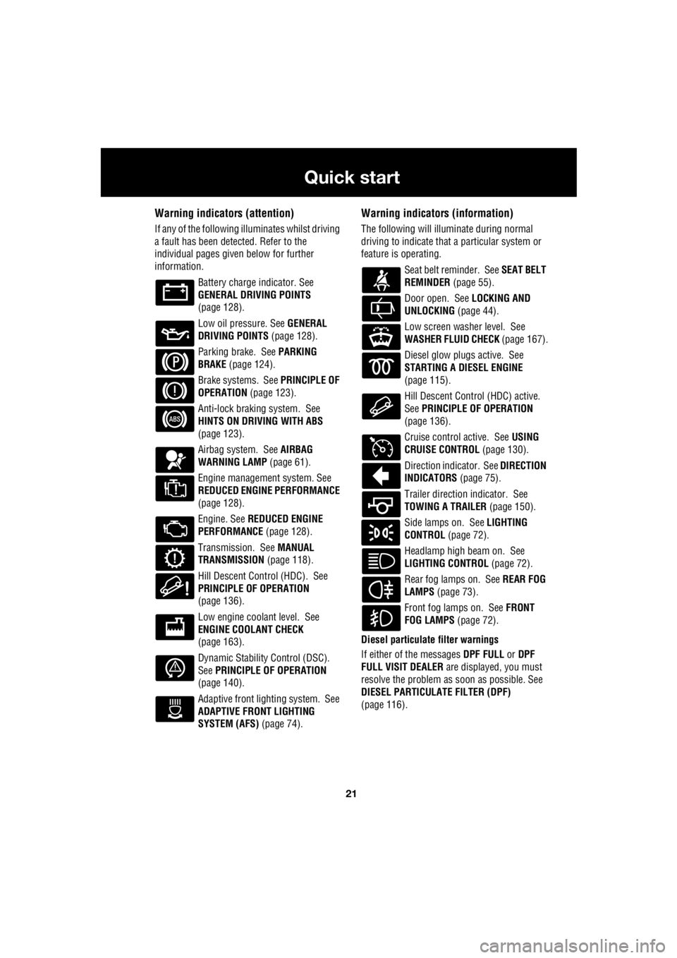
Warning indicators (attention)
If any of the following illuminates whilst driving
a fault has been detected. Refer to the
individual pages give n below for further
information.
Battery charge indicator. See
GENERAL DRIVING POINTS
(page 128).
Low oil pressure. See GENERAL
DRIVING POINTS (page 128).
Parking brake. See PARKING
BRAKE (page 124).
Brake systems. See PRINCIPLE OF
OPERATION (page 123).
Anti-lock braking system. See
HINTS ON DRIVING WITH ABS
(page 123).
Airbag system. See AIRBAG
WARNING LAMP (page 61).
Engine management system. See
REDUCED ENGINE PERFORMANCE
(page 128).
Engine. See REDUCED ENGINE
PERFORMANCE (page 128).
Transmission. See MANUAL
TRANSMISSION (page 118).
Hill Descent Control (HDC). See
PRINCIPLE OF OPERATION
(page 136).
Low engine coolant level. See
ENGINE COOLANT CHECK
(page 163).
Dynamic Stability Control (DSC).
See PRINCIPLE OF OPERATION
(page 140).
Adaptive front lighting system. See
ADAPTIVE FRONT LIGHTING
SYSTEM (AFS) (page 74).
Warning indicators (information)
The following will illuminate during normal
driving to indicate that a particular system or
feature is operating.
Seat belt reminder. See SEAT BELT
REMINDER (page 55).
Door open. See LOCKING AND
UNLOCKING (page 44).
Low screen washer level. See
WASHER FLUID CHECK (page 167).
Diesel glow plugs active. See
STARTING A DIESEL ENGINE
(page 115).
Hill Descent Control (HDC) active.
See PRINCIPLE OF OPERATION
(page 136).
Cruise control active. See USING
CRUISE CONTROL (page 130).
Direction indicator. See DIRECTION
INDICATORS (page 75).
Trailer direction indicator. See
TOWING A TRAILER (page 150).
Side lamps on. See LIGHTING
CONTROL (page 72).
Headlamp high beam on. See
LIGHTING CONTROL (page 72).
Rear fog lamps on. See REAR FOG
LAMPS (page 73).
Front fog lamps on. See FRONT
FOG LAMPS (page 72).
Diesel particulate filter warnings
If either of the messages DPF FULL or DPF
FULL VISIT DEALER are displayed, you must
resolve the problem as soon as possible. See
DIESEL PARTICULATE FILTER (DPF)
(page 116).
Page 2808 of 3229
Wipers and washers
88
L
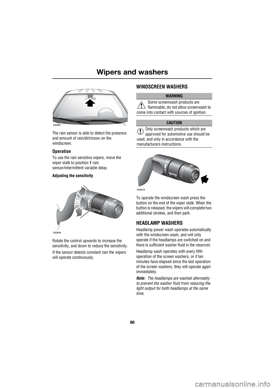
The rain sensor is able to detect the presence
and amount of rain/dirt/snow on the
windscreen.
Operation
To use the rain sensitive wipers, move the
wiper stalk to position 1 rain
sensor/intermittent variable delay.
Adjusting the sensitivity
Rotate the control upwards to increase the
sensitivity, and down to reduce the sensitivity.
If the sensor detects co nstant rain the wipers
will operate continuously.
WINDSCREEN WASHERS
To operate the windscreen wash press the
button on the end of the wiper stalk. When the
button is released, the wi pers will complete two
additional strokes, and then park.
HEADLAMP WASHERS
Headlamp power wash operates automatically
with the windscreen wash, and will only
operate if the headlamps are switched on and
there is sufficient washer fluid in the reservoir.
Headlamp wash operates with every fifth
operation of the screen washers, or if ten
minutes have elapsed si nce the last operation
of the screen washers, they will operate again
immediately.
Note: The headlamps are washed alternately
to prevent the washer fluid from reducing the
light output for both headlamps at the same
time.
E80687
E80684
WARNING
Some screenwash products are
flammable, do not allow screenwash to
come into contact with sources of ignition.
CAUTION
Only screenwash products which are
approved for automotive use should be
used, and only in accordance with the
manufacturers instructions.
E80679
Page 2810 of 3229
Wipers and washers
90
L
Blocked jets
If a washer jet becomes blocked, use a thin
strand of wire to unblock the jet by inserting
the wire into the jet. Ensure that the wire is
completely remove d after unblocking.
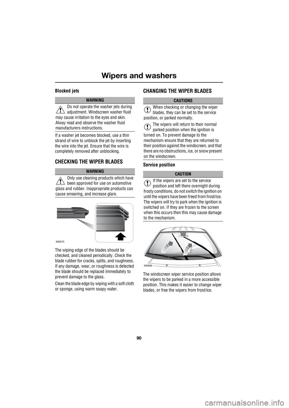
CHECKING THE WIPER BLADES
The wiping edge of the blades should be
checked, and cleaned pe riodically. Check the
blade rubber for cracks , splits, and roughness.
If any damage, wear, or roughness is detected
the blade should be repl aced immediately to
prevent damage to the glass.
Clean the blade edge by wiping with a soft cloth
or sponge, using warm soapy water.
CHANGING THE WIPER BLADES
Service position
The windscreen wiper se rvice position allows
the wipers to be parked in a more accessible
position. This makes it ea sier to change wiper
blades, or free the wipers from frost/ice.
WARNING
Do not operate the washer jets during
adjustment. Windscreen washer fluid
may cause irritation to the eyes and skin.
Alway read and observe the washer fluid
manufacturers instructions.
WARNING
Only use cleaning pr oducts which have
been approved for use on automotive
glass and rubber. Inappr opriate products can
cause smearing, and increase glare.
E80573
CAUTIONS
When checking or changing the wiper
blades, they can be set to the service
position, or parked normally.
The wipers will return to their normal
parked position when the ignition is
turned on. To prevent damage to the
mechanism ensure that they are returned to
their position against th e windscreen, and that
there are no obstructions, ice, or snow present
on the windscreen.
CAUTION
If the wipers are set to the service
position and left there overnight during
frosty conditions, do not switch the ignition on
until the wipers have been freed from frost/ice.
The wipers will try to park when the ignition is
switched on. If they are frozen to the screen
when this occurs then this may cause damage
to the mechanism.
E80582
Page 2878 of 3229
Maintenance
158
L
One or both types of serv ice interval (distance
and time) may be displayed. For example, if an
engine oil service is du e based on mileage, and
a brake fluid change is due based on time, both
distance and time c ountdowns will display.
Service Portfolio
The Service Portfolio book includes a Service
Record section, which enables a record to be
kept of all the servicing and inspections that are
carried out on the vehicle. This section of the
book also has an area for brake fluid changes
to be recorded.
Ensure your service provider signs and stamps
the book after each se rvice and inspection.
Owner Maintenance
In addition to the routine maintenance, a
number of simple checks must be carried out
more frequently. Advice is given on the pages
that follow.
Daily checks
• Operation of lamps, horn, direction
indicators, wipers, washers and warning
indicators.
• Operation of seat belts and brakes.
• Look for fluid deposits underneath the
vehicle that might indicate a leak.
Weekly checks
• Engine oil level. See ENGINE OIL CHECK
(page 162).
• Engine coolant check. See ENGINE
COOLANT CHECK (page 163).
• Brake/clutch fluid level. See BRAKE AND
CLUTCH FLUID CHECK (page 165). •
Power steering fluid level. See POWER
STEERING FLUID CHECK (page 166).
• Screen washer fluid level. See WASHER
FLUID CHECK (page 167).
• Tyre pressure s and condition.
• Operate air conditioning.
Note: The engine oil leve l should be checked
more frequently if the vehicle is driven for
prolonged periods at high speeds.
Driving in arduous conditions
When a vehicle is operated in extremely
arduous conditions, more frequent attention
must be paid to servicing requirements.
For example, if your vehicle experiences deep
wading conditions, even daily servicing could
be necessary to ensure the continued safe and
reliable operation of the vehicle.
Arduous driving conditions include:
• Driving in dusty and/or sandy conditions.
• Driving on rough and/or muddy roads
and/or wading.
• Driving in extremely hot conditions.
• Towing a trailer or driving in mountainous
conditions.
Contact a Land Rover Dealer/Authorised
Repairer for advice.
Emission control
Your vehicle is fitted with various items of
emission and evaporative control equipment,
designed to meet sp ecific territorial
requirements. You should be aware that
unauthorised replacemen t, modification or
tampering with this equipment by an owner or
repair shop, may be unlawful and subject to
legal penalties.
CAUTION
Any significant or sudden drop in fluid
levels, or uneven tyre wear, should be
reported to a qualified technician without
delay.