2006 LAND ROVER FRELANDER 2 length
[x] Cancel search: lengthPage 1962 of 3229
Publi s hed: 11-May-2011
Module Communications Network - Communications Network
Des cript ion and Operat ion
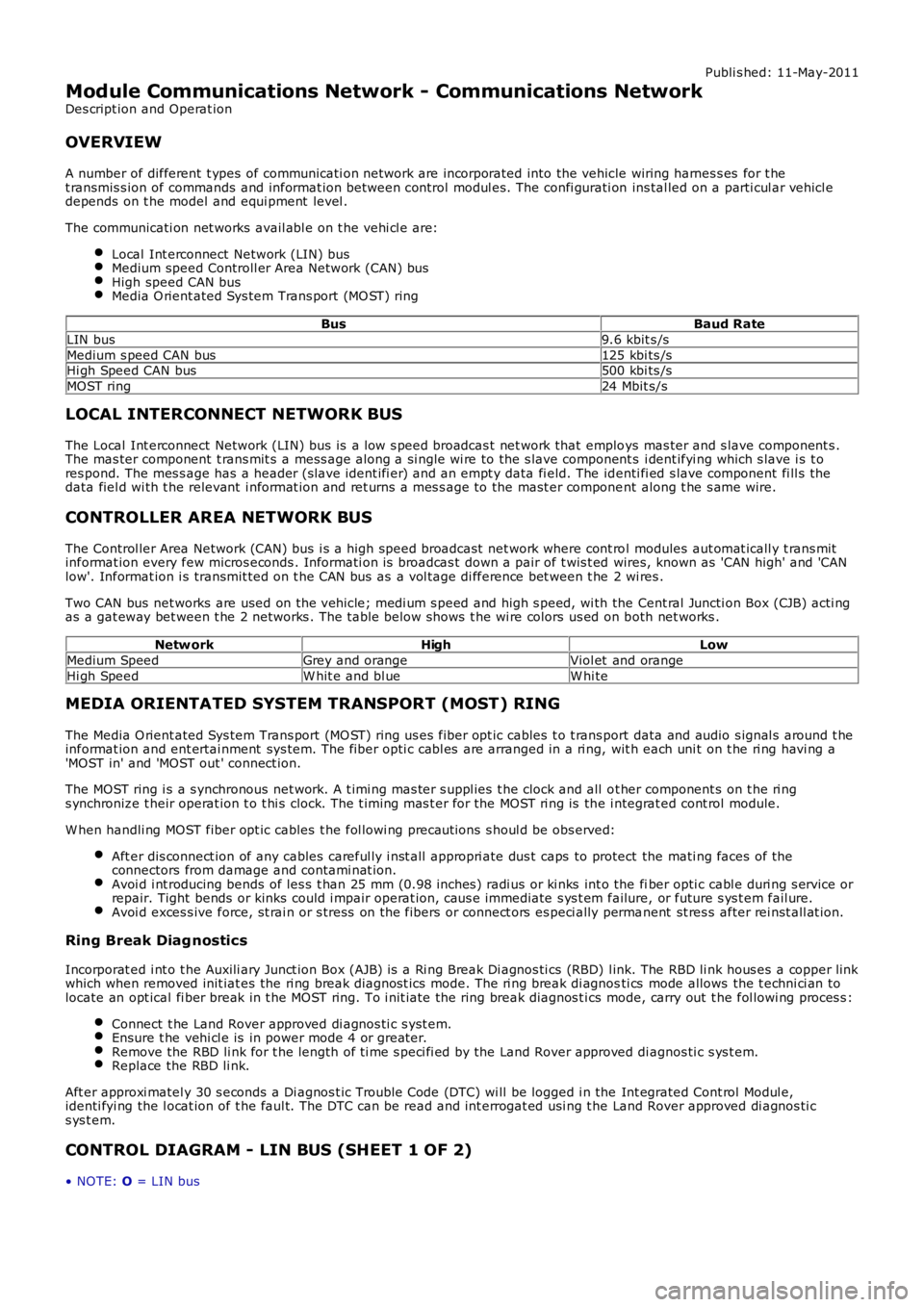
OVERVIEW
A number of different t ypes of communicati on network are incorporated into the vehicle wiring harnes s es for t het ransmis s ion of commands and informat ion between control modul es. The confi gurati on ins tal led on a parti cul ar vehicl edepends on t he model and equi pment level .
The communicati on net works avail abl e on t he vehi cl e are:
Local Int erconnect Network (LIN) busMedium speed Controll er Area Network (CAN) busHigh speed CAN busMedia O rient ated Sys tem Trans port (MO ST) ring
BusBaud Rate
LIN bus9.6 kbit s /s
Medium s peed CAN bus125 kbi ts /sHi gh Speed CAN bus500 kbi ts /s
MOST ring24 Mbit s/s
LOCAL INTERCONNECT NETWORK BUS
The Local Int erconnect Network (LIN) bus is a low s peed broadcas t net work that employs mas ter and s lave component s .The mas ter component t rans mit s a mess age along a si ngle wi re to the s lave component s i dent ifyi ng which s lave i s t ores pond. The mes s age has a header (s lave ident ifi er) and an empt y data fi eld. The identi fi ed s lave component fi ll s thedata fiel d wi th t he relevant i nformat ion and ret urns a mes s age to the mast er component along t he s ame wire.
CONTROLLER AREA NETWORK BUS
The Control ler Area Network (CAN) bus i s a high speed broadcast net work where cont rol modules aut omat icall y t rans mitinformat ion every few micros econds . Informati on is broadcas t down a pair of t wis t ed wires, known as 'CAN high' and 'CANlow'. Informat ion i s transmit ted on t he CAN bus as a vol tage di fference bet ween t he 2 wi res .
Two CAN bus net works are used on the vehicle; medi um s peed and high s peed, wi th the Cent ral Juncti on Box (CJB) acti ngas a gat eway bet ween t he 2 networks . The t abl e below shows t he wi re colors us ed on both net works .
Netw orkHighLow
Medium SpeedGrey and orangeViol et and orange
Hi gh SpeedW hit e and bl ueW hi te
MEDIA ORIENTATED SYSTEM TRANSPORT (MOST) RING
The Media O rient ated Sys tem Trans port (MO ST) ring us es fiber opt ic cables t o t rans port data and audio s ignal s around t heinformat ion and ent ertai nment sys tem. The fiber opti c cabl es are arranged in a ri ng, wit h each uni t on t he ri ng havi ng a'MOST in' and 'MOST out ' connect ion.
The MOST ring i s a s ynchronous net work. A t imi ng mas ter s uppl ies t he clock and all ot her component s on t he ri ngs ynchronize t heir operat ion t o t hi s clock. The t iming mas t er for the MOST ri ng is the i ntegrat ed cont rol module.
W hen handli ng MOST fiber opt ic cables t he fol lowi ng precaut ions s houl d be obs erved:
Aft er dis connect ion of any cables careful ly i nst all appropri ate dus t caps to protect the mati ng faces of theconnectors from damage and contami nat ion.Avoi d i nt roducing bends of les s t han 25 mm (0.98 inches ) radi us or ki nks int o the fiber opti c cabl e duri ng s ervice orrepair. Tight bends or kinks could i mpair operat ion, caus e immediate s ys t em failure, or future s ys t em fail ure.Avoi d exces s ive force, st rai n or s tress on the fibers or connect ors es peci ally permanent st res s after rei nst all at ion.
Ring Break Diag nostics
Incorporat ed i nt o t he Auxili ary Junct ion Box (AJB) is a Ri ng Break Di agnos ti cs (RBD) l ink. The RBD li nk hous es a copper linkwhich when removed init iat es the ri ng break diagnost ics mode. The ri ng break di agnosti cs mode allows the t echni ci an tolocate an opt ical fi ber break in t he MOST ring. To i nit iate the ring break diagnos t ics mode, carry out t he fol lowi ng proces s :
Connect t he Land Rover approved di agnos ti c s yst em.Ensure t he vehi cl e is in power mode 4 or great er.Remove the RBD li nk for t he length of ti me s peci fi ed by the Land Rover approved di agnos ti c s ys t em.Replace the RBD li nk.
Aft er approxi matel y 30 s econds a Di agnos t ic Trouble Code (DTC) wi ll be logged i n the Int egrated Cont rol Modul e,identi fyi ng the l ocat ion of t he faul t. The DTC can be read and int errogat ed usi ng t he Land Rover approved di agnos ti cs ys t em.
CONTROL DIAGRAM - LIN BUS (SHEET 1 OF 2)
• NOTE: O = LIN bus
Page 2015 of 3229
glue l ined heat s hrink s l eeve s o t hat the wiri ng harnes s ins ulat ion becomes damaged.
Two s izes of heat shrink s leeving are s uppl ied i n t he wiring harnes s repai r ki t. Each heat shrink s leeve cont ains a seal antglue. Thes e must be us ed when connect ing wi ri ng harness (s) or el ect ri cal connector termi nal (s ) at all t imes . The s mall erdiamet er heat s hri nk sl eeve is t o be us ed wi th the red and blue but t spl ice connectors and t he larger diamet er sl eeve wit ht he yel low but t s pl ice connect ors .
For eas e and s peed, s ome of t he pre-terminat ed wiring harnes s (s ) may al ready have the ins ul ati on part ly s t ripped at t hes plice end. If t he repai r requires ins ul ati on to be s tripped from the cable, refer to the Relat ions hip Table for the correctlength of ins ul ati on to be s tripped.
The Pre-Termi nat ed W i ri ng Harnes s(s ) il lus trati on shows t he elect rical connector t ermi nal t ype, t he part number of thepre-terminat ed wiring harnes s and t he let ter of t he ext ractor t ip which mus t be us ed to ext ract t he elect rical connect ort ermi nal from the connect or hous ing. Addi ti onal ly, t hos e el ect ri cal connector t ermi nal (s ) which are gold are i dent ified, allothers are t herefore, ti nned and not gold.
W i ri ng Harnes s Cabl e Ident ificati on Sleeves
A s electi on of col ored s leeves are cont ai ned in the wi ri ng harness repair kit for maint ai ning t he wi ring harnes s cableidenti fi cat ion on the pre-t ermi nat ed wi ri ng harness . Place t he correct col ored s l eeve(s ) over the pre-t ermi nat ed wi ri ngharnes s ins ulati on as near to the el ect ri cal connector as pos si ble wi th the main wi ri ng harness cable col or neares t t o t heelectrical connect or.
For example, i f the original wi ring harnes s cable color i s pink wi th a black t race put the pi nk wiring harnes s cableidenti fi cat ion s l eeve on the pre-t ermi nat ed wi ring harnes s firs t foll owed by a bl ack s l eeve, and s lide bot h along t he wi ri ngharnes s cabl e to the el ect ri cal connector t ermi nal.
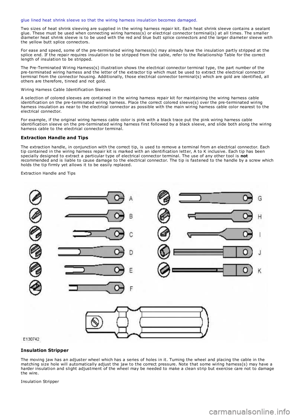
Extraction Handle and Tips
The extract ion handle, in conjuncti on wit h t he correct t ip, is used t o remove a t ermi nal from an electrical connect or. Eacht ip contained i n t he wiring harnes s repai r kit is marked wi th an identi fi cat ion l etter, A t o K inclus ive. Each t ip has beens pecial ly des igned t o extract a parti cul ar t ype of electrical connect or terminal. The us e of any other t ool i s notrecommended and is liabl e to caus e damage t o t he electrical connect or. The t ip i s fas t ened to t he handle by a screw whichholds t he ti p firmly yet all ows it to be eas il y repl aced.
Extract ion Handle and Ti ps
Insulation Stripper
The moving jaw has an adjus t er wheel which has a series of holes i n it . Turning the wheel and placing t he cabl e in themat chi ng si ze hole wi ll automat icall y adjus t the jaw t o t he correct pres s ure. Note that s ome wi ri ng harness (s ) may have aharder ins ulati on and s li ght adjus t ment of the wheel may be needed to make a clean st ri p but exerci se care not to damaget he wire.
Ins ulat ion St ri pper
Page 2016 of 3229
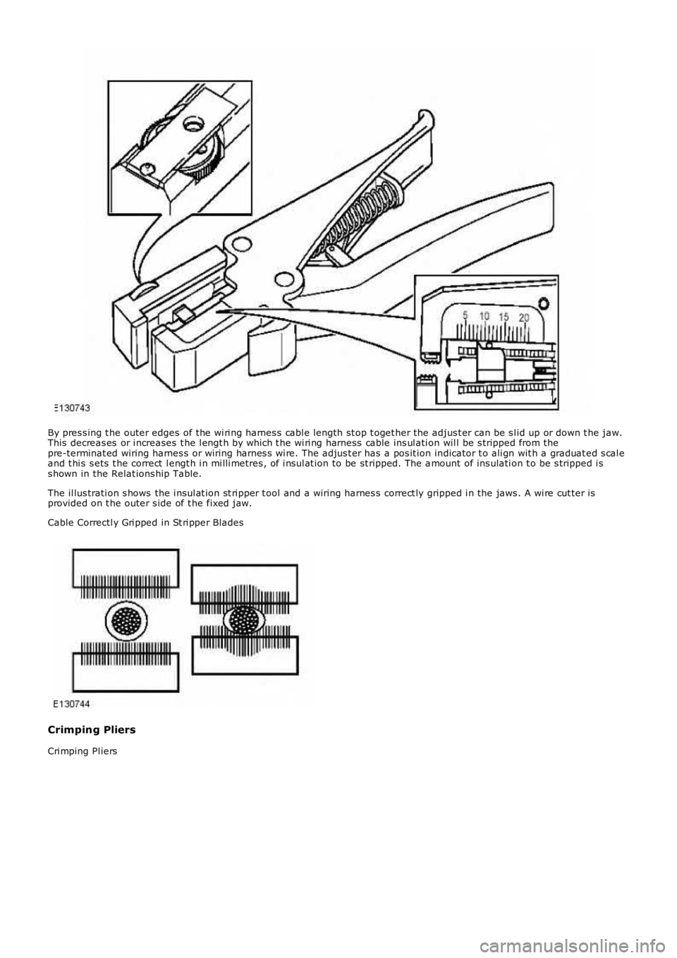
By pres s ing t he outer edges of the wi ri ng harnes s cabl e length st op t oget her the adjus t er can be s l id up or down t he jaw.This decreas es or i ncreases t he l engt h by which t he wi ri ng harness cable ins ul ati on wil l be s tripped from thepre-terminat ed wiring harnes s or wiring harnes s wi re. The adjus t er has a pos it ion indicator t o ali gn wit h a graduat ed s cal eand t hi s s ets t he correct l engt h i n mi lli metres , of i nsul at ion to be st ripped. The amount of ins ulati on t o be s tripped i ss hown in the Relat ions hip Table.
The il lus trati on s hows the i nsul at ion st ri pper t ool and a wiring harnes s correct ly gripped i n the jaws . A wi re cut ter isprovided on t he outer s ide of t he fixed jaw.
Cable Correctl y Gri pped in St ri pper Blades
Crimping Pliers
Cri mping Pl iers
Page 2023 of 3229
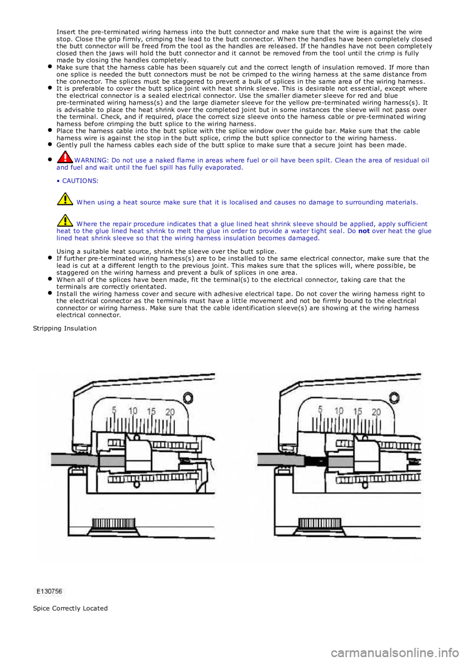
Ins ert the pre-t ermi nat ed wi ring harnes s i nto the but t connect or and make s ure t hat the wire is agains t t he wires top. Clos e t he gri p firmly, crimping t he lead t o t he butt connect or. W hen t he handles have been complet ely clos edt he but t connector wi ll be freed from the t ool as the handles are rel eas ed. If t he handl es have not been complet elyclos ed then t he jaws wil l hol d t he but t connector and i t cannot be removed from the tool unt il t he cri mp i s ful lymade by clos ing the handles complet el y.Make s ure t hat the harnes s cable has been s quarely cut and t he correct length of i nsul ati on removed. If more t hanone s plice i s needed the but t connect ors must be not be crimped t o t he wiring harness at t he s ame dis t ance fromt he connect or. The s pli ces must be st aggered to prevent a bul k of s plices i n the same area of t he wiring harnes s .It is preferable to cover the but t s pl ice joint wit h heat s hrink s l eeve. This i s desi rable not es s ent ial , except wheret he elect rical connect or i s a s ealed el ect ri cal connector. Use the smal ler diamet er sl eeve for red and bl uepre-terminat ed wiring harnes s (s ) and t he large diameter s leeve for the yell ow pre-terminat ed wiring harnes s (s ). Itis advis able to pl ace the heat s hrink over t he compl eted joint but in s ome ins tances the s l eeve wi ll not pass overt he terminal. Check, and i f required, pl ace t he correct s ize sl eeve ont o t he harness cable or pre-t ermi nated wi ri ngharnes s before crimpi ng the but t s plice t o t he wi ring harnes s .Place t he harness cable int o the but t s plice wi th the spl ice window over t he gui de bar. Make s ure that the cableharnes s wire i s agai nst t he s top in t he butt s pli ce, crimp the but t spl ice connector t o t he wiring harnes s .Gentl y pull the harnes s cables each s ide of t he butt s pli ce to make sure t hat a s ecure joint has been made.
W ARNING: Do not use a naked flame in areas where fuel or oi l have been s pil t. Clean t he area of res idual oi land fuel and wait unt il t he fuel s pi ll has ful ly evaporat ed.
• CAUTIO NS:
W hen us i ng a heat source make s ure t hat it is local is ed and causes no damage t o s urroundi ng mat erial s.
W here t he repair procedure i ndicat es t hat a glue l ined heat shrink s leeve s houl d be appli ed, apply s uffici entheat to t he glue lined heat s hri nk to melt t he glue i n order t o provide a water t ight s eal . Do not over heat t he glueli ned heat s hri nk s leeve s o t hat t he wi ring harnes s i nsul ati on becomes damaged.
Us ing a sui table heat s ource, shrink t he s leeve over t he butt s pli ce.If furt her pre-t erminated wi ri ng harnes s(s ) are t o be i nst all ed to the same elect rical connect or, make s ure that thelead i s cut at a different l engt h t o t he previous joi nt. This makes s ure that t he s pl ices wi ll, where poss i bl e, bes taggered on t he wi ri ng harness and prevent a bul k of s pl ices in one area.W hen al l of t he s pli ces have been made, fi t the t erminal(s) t o t he electrical connect or, t aking care t hat thet ermi nal s are correctl y ori ent ated.Ins t all the wiring harnes s cover and s ecure wi th adhes ive electrical tape. Do not cover t he wiring harnes s right tot he elect rical connect or as the t ermi nals mus t have a l it tl e movement and not be firml y bound to t he elect ricalconnector or wiring harnes s . Make s ure t hat the cable i dent ificati on s leeve(s ) are showing at t he wi ri ng harnesselectrical connect or.
Stripping Ins ulati on
Spice Correct ly Located
Page 2507 of 3229
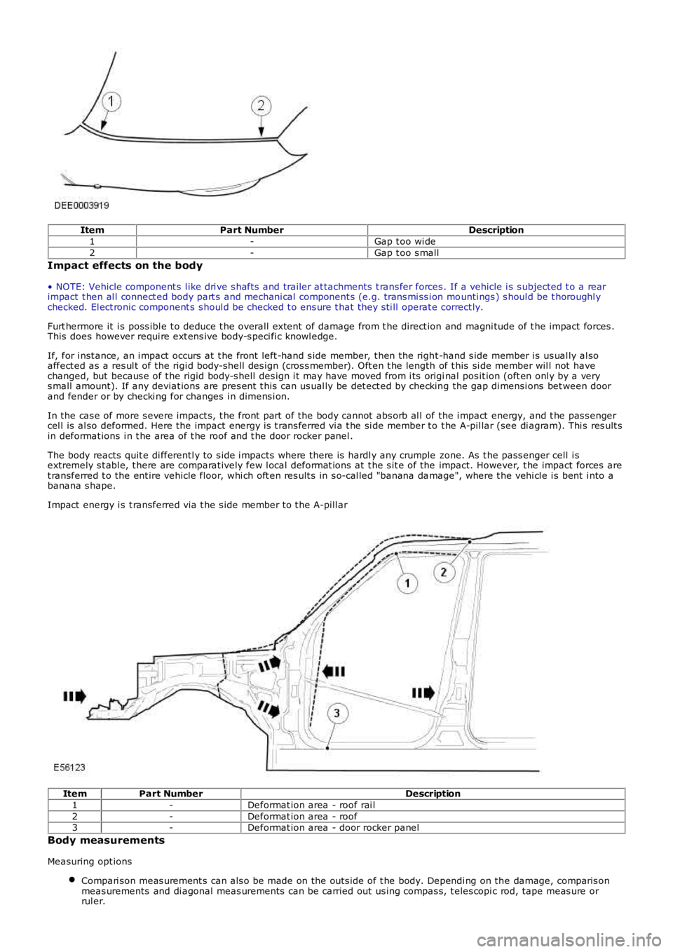
ItemPart NumberDescription
1-Gap t oo wi de
2-Gap t oo s mall
Impact effects on the body
• NOTE: Vehicle component s l ike dri ve s hafts and trailer at tachments t rans fer forces. If a vehicle i s s ubjected t o a rearimpact t hen al l connect ed body part s and mechani cal component s (e.g. trans mi ss i on mounti ngs ) s houl d be t horoughl ychecked. El ect ronic component s s houl d be checked t o ens ure t hat they s ti ll operat e correct ly.
Furt hermore it i s poss ibl e t o deduce t he overall extent of damage from t he direct ion and magni tude of t he impact forces .This does however requi re ext ens ive body-s peci fi c knowl edge.
If, for i nst ance, an i mpact occurs at t he front left -hand s ide member, t hen the right -hand s ide member i s us ual ly al soaffect ed as a res ul t of the rigi d body-s hel l des ign (cros s member). Oft en t he length of t his si de member wil l not havechanged, but becaus e of t he rigid body-s hell des ign i t may have moved from i ts original pos it ion (oft en onl y by a verys mall amount). If any deviat ions are pres ent t his can us ual ly be det ect ed by checking the gap di mensi ons bet ween doorand fender or by checki ng for changes i n dimens i on.
In the cas e of more s evere impact s, t he front part of the body cannot abs orb al l of the i mpact energy, and t he pas s engercel l is al so deformed. Here the impact energy is t rans ferred vi a t he si de member t o t he A-pil lar (see di agram). Thi s res ult sin deformat ions i n t he area of t he roof and t he door rocker panel .
The body reacts quit e di fferentl y to s ide i mpact s where there is hardl y any crumple zone. As t he pass enger cell i sextremely s t abl e, t here are comparat ively few l ocal deformat ions at t he s it e of the impact. However, t he impact forces aret ransferred t o the ent ire vehicle floor, whi ch oft en res ult s in s o-cal led "banana damage", where t he vehi cl e i s bent i nto abanana s hape.
Impact energy i s t ransferred via t he s ide member to t he A-pill ar
ItemPart NumberDescription
1-Deformat ion area - roof rai l
2-Deformat ion area - roof3-Deformat ion area - door rocker panel
Body measurements
Measuring opt ions
Compari son meas urement s can als o be made on the out s ide of t he body. Dependi ng on the damage, comparis onmeas urements and di agonal meas urements can be carried out us ing compas s, t eles copi c rod, tape meas ure orrul er.
Page 2508 of 3229
• NOTE: The s ame reference point s mus t be chos en on bot h s ides when checking for changed dimens ions (e.g.bores , edges , beads /s wage l ines etc).
All of t he important external body dimens ions are li st ed in Tol erance Checks .For addit ional informat ion, refer t o: Body and Frame (501-26 Body Repai rs - Vehi cl e Speci fi c Informat ion andTolerance Checks , Descripti on and Operat ion).
Measurements wi th a meas uri ng/s trai ghtening jig.A meas uri ng/s traightening ji g is required for accurat e meas urement s of the body. The measuring s yst ems arecat egoris ed by t heir means of operati on:Mechanical meas uring s ys tem.Opti cal meas uri ng s ys t em.
Quick and accurate meas uri ng res ult s can be obtai ned usi ng comput eri sed meas uring s yst ems .
A minimum of t hree int act meas uri ng point s on t he body are requi red for meas urement s of length, wi dth and hei ghtdimens ions .
In s ome cases t his may mean making t he meas uri ng poi nts access ibl e. Al l of thes e meas uring sys tems can be used t omake body meas urements , provided al l t he equipment is avail able.
Planning a repair
The fol lowing decis i ons have t o be made before t he repai rs are s tarted:
Does the vehicl e need to be put on a s traightening ji g, or can it be st rai ght ened by other means ?Does the body need t o be meas ured?Do aggregates l ike engine or axles need t o be removed?• NOTE: It is preferable to repair body part s rat her t han t o renew them, as t his keeps the complet e body-s hel lint act .
W hi ch body parts need t o be renewed?W hi ch body parts can be repai red?
Obtaining spare parts
The avai labil it y of s pare part s oft en determines how eas il y t he body repairs can be carri ed out . The fol lowi ng procedure isrecommended:
Obtai n all t he data for the vehicl e, i ncl udi ng t ype, vehi cl e i dent ificati on number, trim code, engine i dent ificati onlet ters, i nit ial regis t rat ion et c.Es tabli sh all of the metal part s that need t o be renewed.Es tabli sh all of the at tached part s t hat need t o be renewed, including smal l parts li ke ri vet s, cl ips etc.
Straightening repairs
W ARNING: The us e of heat when pull ing t o s traighten body panels , (s uch as s ide members ), i s not recommended.Longi tudinal pulli ng, (hot or col d), is al s o not recommended. A smal l amount of s ide to si de pull is permis s ibl e, (col d).
W hen any t ype of pul li ng or st rai ght ening operat ion i s performed i t is i mport ant to obs erve for any movement i n adjacentpanel s.
A panel must retai n it s s t rength and integrit y, i f there is any doubt the panel mus t be renewed.
Straightening repairs are often required to res tore the body t o i ts origi nal s hape aft er an accident. This can be done wit h:
Ali gnment jigs .Univers al s trai ghtening and meas uri ng ji gs.W el di ng jig s ys tem.
The fol lowing poi nts mus t be foll owed to ens ure that t he repairs are carri ed out profes si onal ly and t hat all t he dimens ionsare correct aft er t he repai rs have been carri ed out.
Struct ure:- The repair s equence depends on the individual repair plan (t aki ng any neces sary dis as sembl y work intoaccount).- Clean t he at tachment areas .- Anchor t he vehi cl e free of s tres s on t he relevant s ys t em.- Support the aggregat es to take s train off the body.- Decide on at l eas t t hree meas uri ng/mounti ng poi nts that are undamaged and as far apart as pos s ible (forbasi c adjus tment ).- Check the di mens i ons of t he meas uri ng/mounti ng poi nts .Straightening:-• NOTE: Check di mensi ons and gaps conti nuous ly during s t raight eni ng.
A body i s always s traightened i n the oppos it e direct ion t o t hat of the i mpact . Always carry out st rai ght eningrepairs wi th the complet e body s hel l as s embled (do not cut out any part s beforehand). Carry out t hes traightening work i n s everal s t ages . This prevents the ris k of over st ret chi ng or of welded joi nts t eari ng out .Duri ng the individual st rai ght ening s t eps , rel ieve t ens i on by s triking wi th an aluminium hammer whi le the part iss ubject ed t o a t ensi le load (in t he area of pre-determined folding poi nt s , dent s , welded joi ns etc.).Speci al feat ures :- Ult ra high s t rength st eel cannot be st rai ght ened due to it s bri tt lenes s and mus t always be repl aced.
Cutting out body parts
Page 2642 of 3229
Publ is hed: 11-May-2011
Rear End Sheet Metal Repairs - Rear Side Member Section
Removal and Installation
Removal
• NOTE: The rear side member section is cut from the rear side member service panel. The section is approximately
410mm in length and is serviced with the rear side member lower extension.
• NOTE: It is necessary to remove the spare wheel well to allow access to the rear side member section.
1. The rear side member section is replaced in conjunction with:
Rear bumper cover
Re a r bumpe r a rma t ure
Back panel
Re a r bumpe r mo unt i ng
Inner back panel assembly
Re a r s i de me mbe r cl os i ng pa ne l .
Spare wheel well
Fuel t ank
Rear subframe and suspension assembly
2. Fo r a d d i t i o na l i nf o rma t i o n re l a t i ng t o t hi s re p a i r p ro ce d ure
please see the following:
Fo r a d d i t i o na l i nf o rma t i o n, re f e r t o : Body and Frame
(501-26
Body Repairs - Vehicle Specific Information and Tolerance
Checks, Description and Operation) /
St a nd a rd W o rks ho p P ra ct i ce s
(100-00 Ge ne ra l I nf o rma t i o n,
Description and Operation).
3. Re move t he re a r s i de me mbe r cl os i ng pa ne l .
Fo r a d d i t i o na l i nf o rma t i o n, re f e r t o : Rear Side Member Closing
Panel (501-30 Rear End Sheet Metal Repairs, Removal and
Installation).
4. Remove the rear subframe / suspension as an assembly.
Fo r a d d i t i o na l i nf o rma t i o n, re f e r t o : Rear Subframe
(502-00
Uni-Body, Subframe and Mounting System, Removal and
Installation).
5. Remove the fuel tank.
Fo r a d d i t i o na l i nf o rma t i o n, re f e r t o : Fuel Tank
(310-01A Fuel
Tank and Lines - I6 3.2L Petrol, Removal and Installation).
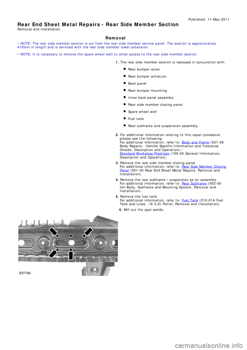
6. Mill out the spot welds.
Page 2792 of 3229
Lighting
72
L
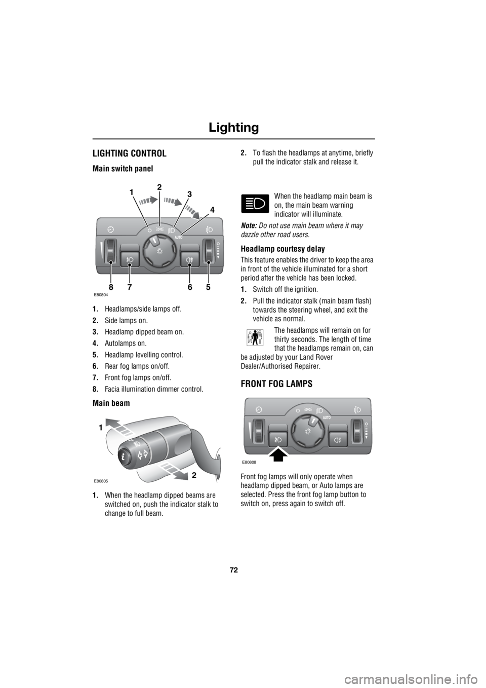
LightingLIGHTING CONTROL
Main switch panel
1. Headlamps/side lamps off.
2. Side lamps on.
3. Headlamp dipped beam on.
4. Autolamps on.
5. Headlamp levelling control.
6. Rear fog lamps on/off.
7. Front fog lamps on/off.
8. Facia illumination dimmer control.
Main beam
1.When the headlamp dipped beams are
switched on, push the indicator stalk to
change to full beam. 2.
To flash the headlamps at anytime, briefly
pull the indicator stalk and release it.
When the headlamp main beam is
on, the main beam warning
indicator will illuminate.
Note: Do not use main beam where it may
dazzle other road users.
Headlamp courtesy delay
This feature enables the driver to keep the area
in front of the vehicle illuminated for a short
period after the vehicle has been locked.
1. Switch off the ignition.
2. Pull the indicator stalk (main beam flash)
towards the steering wheel, and exit the
vehicle as normal.
The headlamps will remain on for
thirty seconds. The length of time
that the headlamps remain on, can
be adjusted by your Land Rover
Dealer/Authorised Repairer.
FRONT FOG LAMPS
Front fog lamps will only operate when
headlamp dipped beam, or Auto lamps are
selected. Press the front fog lamp button to
switch on, press again to switch off.
E808047865
123
4
1
2E80805
E80808