2006 LAND ROVER FRELANDER 2 roof
[x] Cancel search: roofPage 2432 of 3229
2. CAUTION: Do not all ow t he roof opening panel bl ind t ube to
rot ate unt il t he plas t ic pin is s ecure i n it s l ocat or.
Secure t he met al pi n to it s locator. Remove t he locki ng pin from t he roof openi ng panel bl ind.2.
Carefully sl ide t he roof opening panel bl ind t ube to the right . Ali gn and s ecure t he plas ti c pin t o i ts l ocat or.3.
Open t he roof openi ng panel bl ind.
4.
Secure t he headl iner.
5.
At tach t he front door s eal s .
6.
At tach t he rear of the headli ner.
7.
Inst all t he pas s enger as s is t handl es .
8.
Inst all t he s un vi s ors .
9.
Inst all t he int erior rear vi ew mi rror.
Refer t o: Int erior Rear View Mirror (501-09 Rear Vi ew Mi rrors ,
Removal and Ins tall ati on).
10.
Inst all t he D-pi llar t ri m panels .
Refer t o: D-Pi llar Trim Panel (501-05 Int eri or Trim and
Ornament ati on, Removal and Ins tal lat ion).
11.
Inst all t he C-pi llar t ri m panels .
Refer t o: C-Pil lar Tri m Panel (501-05 Int erior Trim and
Ornament ati on, Removal and Ins tal lat ion).
12.
Inst all t he B-pi llar t ri m panels .
Refer t o: B-Pil lar Upper Trim Panel (501-05 Interior Tri m and
Ornament ati on, Removal and Ins tal lat ion).
13.
Inst all t he A-pi llar t ri m panels .
Refer t o: A-Pil lar Tri m Panel (501-05 Int erior Trim and
Ornament ati on, Removal and Ins tal lat ion).
14.
Page 2483 of 3229
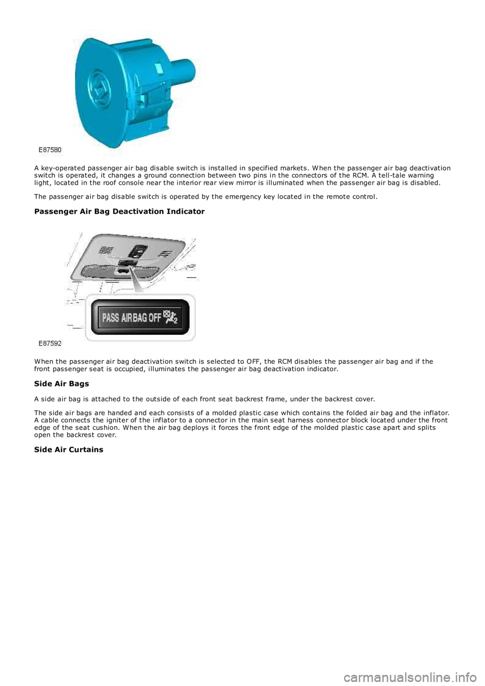
A key-operat ed pass enger ai r bag di s abl e s wit ch is ins tall ed in specified market s . When t he pass enger ai r bag deacti vat ions wit ch is operat ed, it changes a ground connect ion bet ween two pins i n the connect ors of t he RCM. A t ell -t ale warningli ght , located in t he roof consol e near t he i nt eri or rear vi ew mirror is i ll uminated when the pas s enger air bag i s dis abled.
The pass enger ai r bag dis abl e s wit ch is operat ed by t he emergency key locat ed i n t he remot e cont rol .
Passenger Air Bag Deactivation Indicator
W hen t he pas senger ai r bag deact ivati on s wit ch is s elected to O FF, t he RCM dis ables t he pas senger ai r bag and if t hefront pas s enger s eat is occupi ed, i ll uminates t he pas senger ai r bag deact ivati on indicator.
Side Air Bags
A s i de air bag is at t ached t o t he out s ide of each front seat backrest frame, under the backres t cover.
The s ide ai r bags are handed and each cons i st s of a mol ded plas ti c cas e whi ch cont ains t he fol ded ai r bag and the infl ator.A cable connect s t he ignit er of t he i nflat or to a connector in the main s eat harness connect or block locat ed under the frontedge of the s eat cus hion. W hen t he air bag deploys i t forces t he front edge of t he mol ded plas ti c cas e apart and s pli tsopen the backres t cover.
Side Air Curtains
Page 2495 of 3229
Publi s hed: 11-May-2011
Supplemental Restraint System - Side Air Curtain Module
Removal and Inst all ati on
Removal
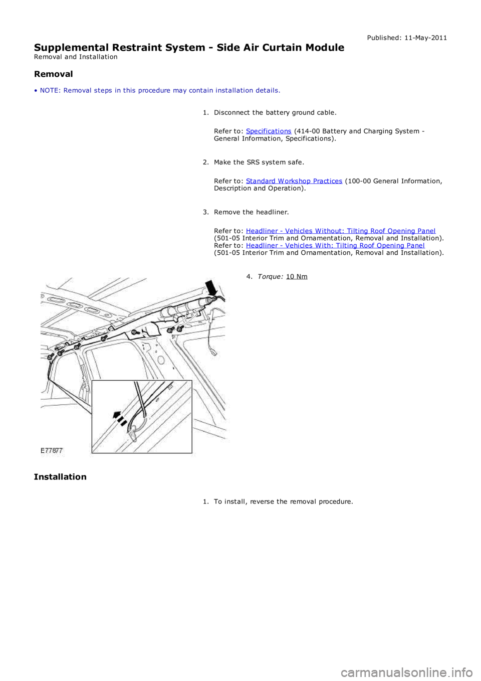
• NOTE: Removal s t eps in t his procedure may cont ain i nst all ati on det ail s.
Di sconnect t he bat t ery ground cable.
Refer t o: Specificati ons (414-00 Bat tery and Charging Sys tem -
General Informat ion, Specificati ons).
1.
Make t he SRS s ys t em s afe.
Refer t o: Standard W orks hop Pract ices (100-00 General Informat ion,
Des cript ion and Operat ion).
2.
Remove t he headl iner.
Refer t o: Headl iner - Vehi cl es W i thout: Ti lt ing Roof Opening Panel (501-05 Int eri or Trim and Ornament ati on, Removal and Ins tal lati on).
Refer t o: Headl iner - Vehi cl es W i th: Ti lt ing Roof Openi ng Panel (501-05 Int eri or Trim and Ornament ati on, Removal and Ins tal lati on).
3. T orque:
10 Nm 4.
Installation To i nst all , revers e t he removal procedure.
1.
Page 2503 of 3229
Publi s hed: 11-May-2011
Body Repairs - General Information - Body Repairs
Des cript ion and Operat ion
General Information
Introduction
The body plays a s ignificant role in the i ncreas i ng trend of ever more rapi dl y changing model vari ant s . The differentcus t omer groups are s t rongly i nfl uenced by t he des i gn and s hape of t he body. At t he s ame t ime the s t abi li ty of t he bodyplays t he mos t important part i n ensuring pas senger and driver s afet y. Light weight cons truct ion, alt ernat ive mat erial s,compos i te materi als , plas ti cs and appropriat e joi ning proces ses are all des ign feat ures t hat charact eris e modern LandRover vehicle bodies .
In terms of manufacturing t echnology, modern s afet y cell bodi es can be produced al mos t wit hout any probl ems . LandRover guarant ee high qualit y s t andards by ens uri ng t hat mechanical s t rength propert ies are tried and t es ted i n numerouscomput er s imulat ions , crash tes t s, by t es ti ng materials and by employing s ophi s ti cated manufacturing t echnologies . In theevent of repai rs i t is vi tal t hat t he producti on qual it y s tandards are uphel d. This requires a well -equipped works hop, andplaces part icul ar emphas is on the qual ifi cat ions of t he works hop technicians. Up-to-date knowledge of currentmanufacturing t echnologies and conti nuous t rai ni ng on new repai r met hods and t echniques are vit al for high-quali ty bodyrepairs . The model -s peci fi c repair manuals and the general repair t echni ques provi de val uabl e s upport when undertakingbody repairs.
Always follow the repair ins t ructi ons publi s hed in t his manual. Fail ure t o obs erve this i nst ructi on can res ult i n s eri ousimpai rment of vehi cle s afet y. Al l s pecified s afet y requi rements must be met aft er the work has been carri ed out.
Vehicle design
T he body
The Freelander 2 body is manufact ured l ike a convent ional monocoque. Two monos i des are welded t o t he floor, roof andbulkheads , creati ng a s t rong, si ngl e s truct ure. Dual Phas e (DP), and Bake Hardened (BH), s t eel s are us ed i n t he s ide panelrei nforcements . DP s t eel i s als o us ed for t he rear of t he front si de member, for added st rength in front and s ide impacts .The roof s truct ure can accommodate a roof openi ng panel . W hen a s unroof is not fit ted, t he outer roof panel i s a s i ngl elarge s teel pres si ng wi th s t yled s wages to add st rengt h and prevent boomi ng.
The s afety of the driver and the pas s engers is paramount for every body des ign. There are two key safety as pect sin the body:
Safet y pas s enger cellCrumpl e zones
Safet y pas s enger cell
Stable pill ars , rocker panel and door profil es.Side i mpact protecti on in the doors .Doors are desi gned to open even i n t he event of ext reme deformati on.
Crumpl e zone
Dynamic abs orpti on of deforming forces .Prot ect ion of t he pass enger cell .
Vehicle Design
Page 2507 of 3229
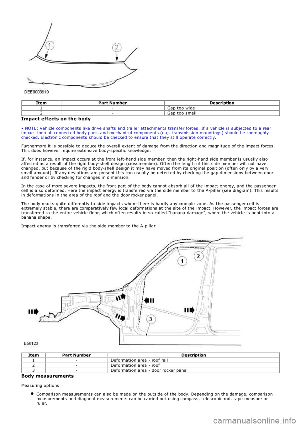
ItemPart NumberDescription
1-Gap t oo wi de
2-Gap t oo s mall
Impact effects on the body
• NOTE: Vehicle component s l ike dri ve s hafts and trailer at tachments t rans fer forces. If a vehicle i s s ubjected t o a rearimpact t hen al l connect ed body part s and mechani cal component s (e.g. trans mi ss i on mounti ngs ) s houl d be t horoughl ychecked. El ect ronic component s s houl d be checked t o ens ure t hat they s ti ll operat e correct ly.
Furt hermore it i s poss ibl e t o deduce t he overall extent of damage from t he direct ion and magni tude of t he impact forces .This does however requi re ext ens ive body-s peci fi c knowl edge.
If, for i nst ance, an i mpact occurs at t he front left -hand s ide member, t hen the right -hand s ide member i s us ual ly al soaffect ed as a res ul t of the rigi d body-s hel l des ign (cros s member). Oft en t he length of t his si de member wil l not havechanged, but becaus e of t he rigid body-s hell des ign i t may have moved from i ts original pos it ion (oft en onl y by a verys mall amount). If any deviat ions are pres ent t his can us ual ly be det ect ed by checking the gap di mensi ons bet ween doorand fender or by checki ng for changes i n dimens i on.
In the cas e of more s evere impact s, t he front part of the body cannot abs orb al l of the i mpact energy, and t he pas s engercel l is al so deformed. Here the impact energy is t rans ferred vi a t he si de member t o t he A-pil lar (see di agram). Thi s res ult sin deformat ions i n t he area of t he roof and t he door rocker panel .
The body reacts quit e di fferentl y to s ide i mpact s where there is hardl y any crumple zone. As t he pass enger cell i sextremely s t abl e, t here are comparat ively few l ocal deformat ions at t he s it e of the impact. However, t he impact forces aret ransferred t o the ent ire vehicle floor, whi ch oft en res ult s in s o-cal led "banana damage", where t he vehi cl e i s bent i nto abanana s hape.
Impact energy i s t ransferred via t he s ide member to t he A-pill ar
ItemPart NumberDescription
1-Deformat ion area - roof rai l
2-Deformat ion area - roof3-Deformat ion area - door rocker panel
Body measurements
Measuring opt ions
Compari son meas urement s can als o be made on the out s ide of t he body. Dependi ng on the damage, comparis onmeas urements and di agonal meas urements can be carried out us ing compas s, t eles copi c rod, tape meas ure orrul er.
Page 2512 of 3229
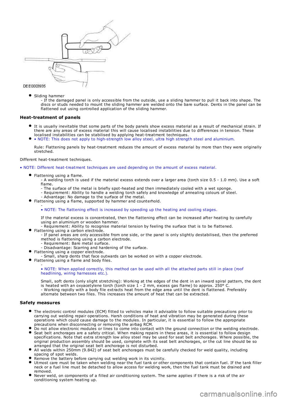
Sli di ng hammer- If the damaged panel i s only acces s ibl e from t he outs i de, us e a sl iding hammer to pul l i t back into shape. Thedis cs or st uds needed t o mount t he s li di ng hammer are welded onto the bare s urface. Dent s i n t he panel can befl att ened out us ing cont roll ed appl icati on of the s l iding hammer.
Heat-treatment of panels
It is us ually inevi tabl e that s ome parts of t he body panels show exces s material as a resul t of mechanical st rai n. Ift here are any areas of exces s material t hi s wi ll caus e l ocali s ed ins tabil it ies due to di fferences i n t ens ion. Theselocali sed i nst abil it ies can be s tabil is ed by applying heat -t reat ment techni ques .• NOTE: This does not appl y t o high-s t rength low al loy s t eel , ult ra hi gh s trengt h s teel and alumi nium.
Rule: Flat tening panels by heat -t reat ment reduces t he amount of excess material by more than t hey were origi nal lys tretched.
Different heat -t reatment t echni ques .
• NOTE: Different heat -t reat ment techni ques are us ed depending on the amount of exces s mat erial .
Flat tening us ing a fl ame.- A wel ding t orch i s used if t he material exces s extends over a larger area (t orch size 0.5 - 1.0 mm). Us e a s oftfl ame.- The s urface of t he met al i s bri efl y s pot -heat ed and then i mmediat ely cooled wi th a wet s ponge.- Requi rement : Abili ty to handle a weldi ng torch safely and knowledge of anneali ng col ours of s teel .- Advant age: No damage to the s urface of the met al.Flat tening us ing a fl ame, support ed by hammer and count erhold.-• NOTE: The flatt ening effect is i ncreas ed by s peedi ng up t he heat ing and cooli ng s tages .
If the mat eri al excess is concentrated, t hen the flat tening effect can be increas ed aft er heat ing by carefullyus ing an al uminium or wooden hammer.- Requi rement : Abili ty to recognis e material tens ion by feeling the s urface that is to be fl att ened.Flat tening us ing a carbon electrode.- If panel areas are onl y acces s ible from one s ide, or the panel is onl y s light ly des tabil is ed, then t he preferredmet hod is flat tening us ing a carbon electrode.- Requi rement : Bare met al s urface.- Dis advant age: Scarring and hardening of t he s urface.Flat tening us ing a copper electrode.- Small , s harp dents t hat face outwards can be worked on wi th a copper electrode.Flat tening us ing a fl ame and body fi les .-• NOTE: W hen appli ed correct ly, thi s method can be us ed wi th al l the at t ached part s s ti ll i n place (roofheadl ining, wi ring harnes s es etc.).
Small , soft dent s (onl y s li ght s t ret chi ng): W orki ng at t he edges of t he dent i n an inward s piral pat tern, the dentis heat ed wit h an oxyacet yl ene torch (t orch s ize 1 - 2 mm, exces s gas fl ame) to approx. 250° C.- W orking rapi dly wi th a body fi le ext racts heat from the edge area unt il t he dent is flat tened. Preferabl yalt ernate bet ween t wo files . This i ncreas es t he amount of heat t hat can be ext racted.
Safety measures
The electroni c cont rol modules (ECM) fi tt ed t o vehicles make i t advi sable to foll ow s uit able precauti ons prior t ocarryi ng out wel ding repai r operati ons . Hars h condit ions of heat and vibrati on may be generat ed during t heseoperati ons which coul d caus e damage t o t he modules . In part icul ar, i t is es s ent ial to fol low the appropriateprecaut ions when di sconnect ing or removi ng the ai rbag RCM.Do not all ow electronic modules or l ines t o come int o contact wit h t he ground connecti on or the wel ding elect rode.Seat bel t anchorages are a s afety crit ical. W hen maki ng repairs i n t hes e areas , it is es s ent ial t o fol low des igns pecificati ons. Not e t hat ext ra s t rength low al loy s t eel may be us ed for seat belt anchorages . W here poss i bl e, theori ginal product ion as s embl y s houl d be us ed, compl et e wi th it s s eat bel t anchorages, or t he cut line should be soarranged t hat the origi nal s eat bel t anchorage i s not dis turbed.All wel ds wit hin 250mm (9.842) of s eat bel t anchorages mus t be careful ly checked for weld quali ty, includings pacing of s pot welds .Remove the bat tery before carryi ng out wel ding work in it s vicinit y.Ut most care mus t be taken when wel di ng near the fuel t ank or other components that cont ain fuel. If the t ank fi ll erneck or a fuel li ne mus t be detached to al low access for weldi ng work, then t he fuel t ank mus t be drained andremoved.Never wel d, on components of a fi lled ai r condit ioning sys tem. The same appl ies i f there is a ri sk of t he aircondi ti oni ng s ys t em heati ng up.
Page 2529 of 3229
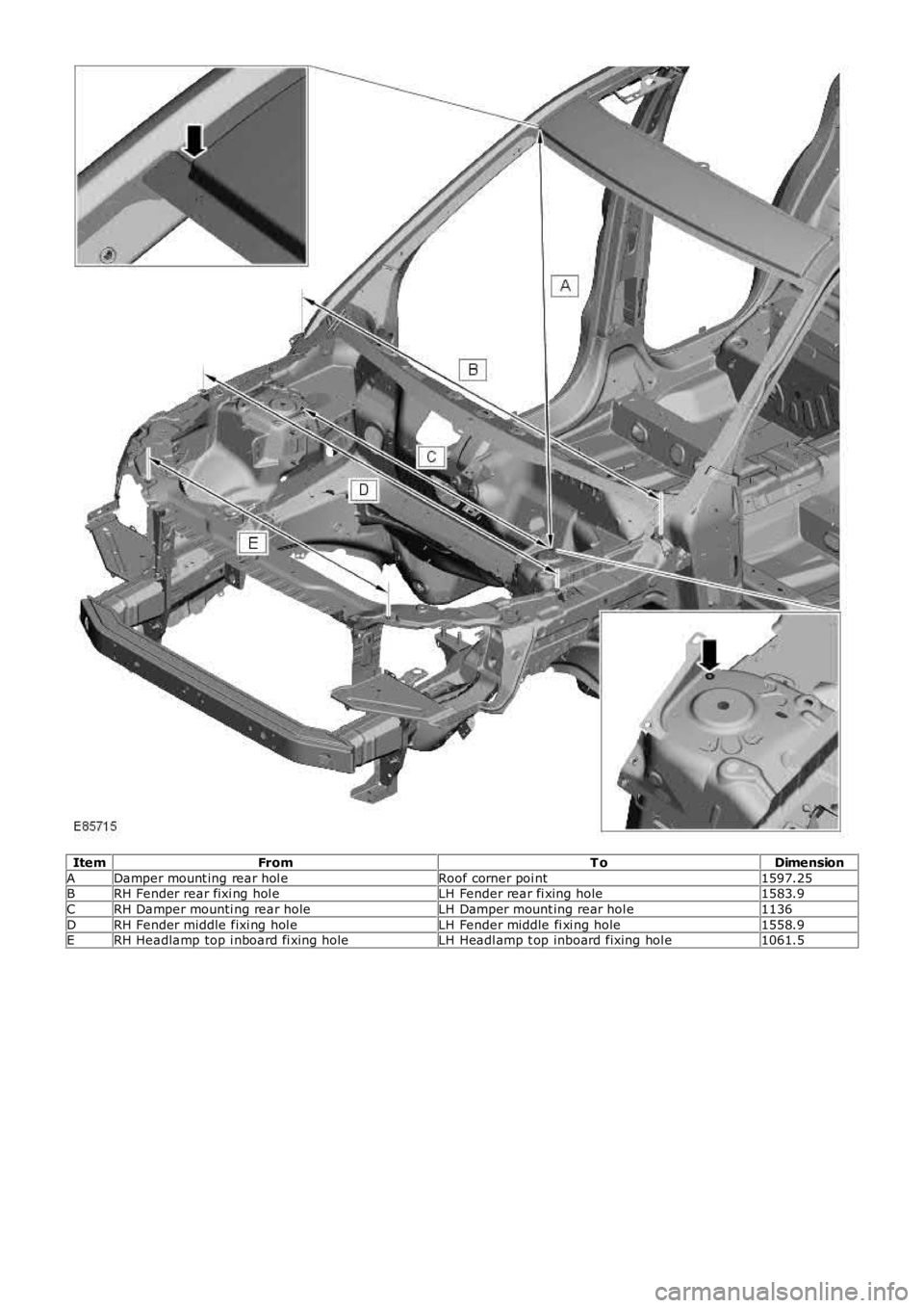
ItemFromT oDimension
ADamper mount ing rear hol eRoof corner poi nt1597.25BRH Fender rear fixi ng hol eLH Fender rear fi xing hole1583.9
CRH Damper mounti ng rear holeLH Damper mount ing rear hol e1136
DRH Fender middle fixi ng hol eLH Fender middle fi xi ng hole1558.9ERH Headlamp top i nboard fi xing holeLH Headl amp t op inboard fixing hol e1061.5
Page 2579 of 3229
Publ is hed: 11-May-2011
Roof Sheet Metal Repairs - Roof
Description and Operation
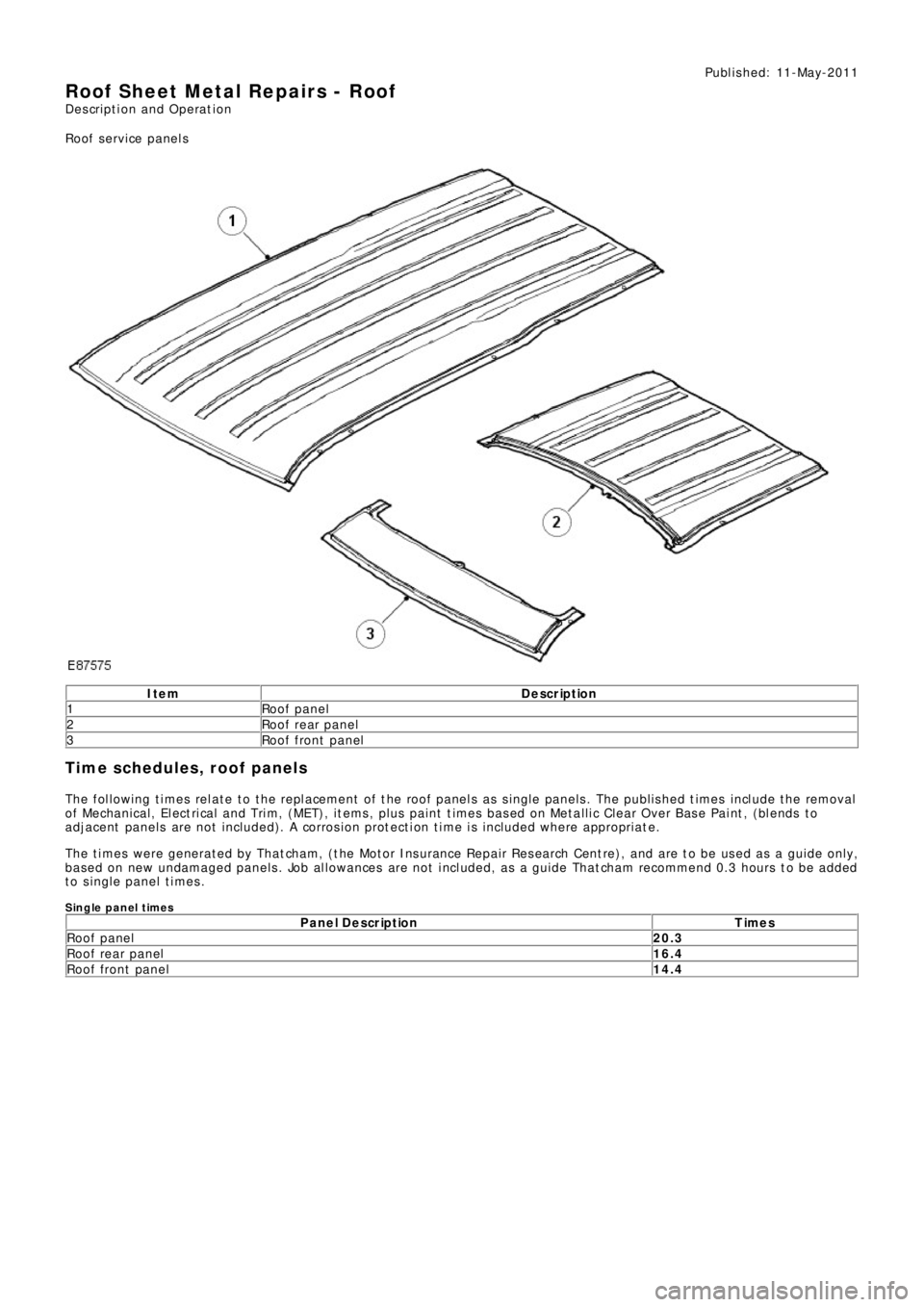
Roof service panels
Ite m De scription
1Roof panel
2 Roof rear panel
3 Roof front panel
Time schedules, roof panels
The following times relate to the replacement of the roof panels as single panels. The published times include the removal
of Mechanical, Electrical and Trim, (MET), items, plus paint times based on Metallic Clear Over Base Paint, (blends to
adjacent panel s are not i ncl ude d). A corros i on prot ect i on t i me i s i ncl ude d where appropri at e .
The times were generated by Thatcham, (the Motor Insurance Repair Research Centre), and are to be used as a guide only,
based on new undamaged panels. Job allowances are not included, as a guide Thatcham recommend 0.3 hours to be added
to single panel times.
Single panel timesP a n e l D e s c r ip t io n T ime s
Roof panel20.3
Roof rear panel16.4
Roof front panel14.4