2006 LAND ROVER FRELANDER 2 navigation
[x] Cancel search: navigationPage 115 of 3229
Publ is hed: 28-Apr-2011
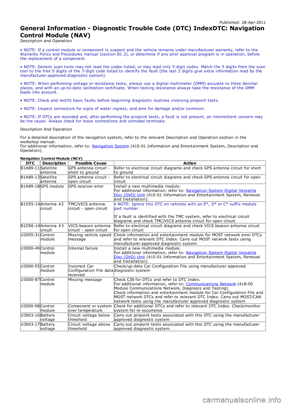
General Information - Diagnostic Trouble Code (DTC) IndexDTC: Navigation
Control Module (NAV)
Des cript ion and Operat ion
• NOTE: If a cont rol module or component i s s uspect and the vehicl e remai ns under manufacturer warrant y, refer t o t heW arranty Pol icy and Procedures manual (s ect ion B1.2), or determine i f any pri or approval program is i n operat ion, beforet he replacement of a component.
• NOTE: Generic scan t ool s may not read the codes li st ed, or may read only 5-digi t codes . Match t he 5 digi ts from t he s cant ool t o t he fi rs t 5 di gi ts of the 7-digit code li s ted t o i dent ify the fault (the last 2 digi ts gi ve ext ra informati on read by themanufacturer-approved di agnos ti c s ys t em).
• NOTE: W hen performing volt age or res is t ance t est s , always use a digi tal mult imeter (DMM) accurat e t o t hree deci malplaces, and wi th an up-t o-date cal ibrat ion cert ificate. W hen tes ti ng res is t ance al ways take t he res is t ance of t he DMMleads i nt o account .
• NOTE: Check and recti fy bas ic faul ts before beginni ng diagnos t ic rout ines i nvol vi ng pinpoint t es t s.
• NOTE: Ins pect connect ors for s igns of water ingres s , and pins for damage and/or corros ion.
• NOTE: If DTCs are recorded and, aft er performi ng the pi npoi nt tes ts , a fault is not present , an int ermi tt ent concern maybe t he caus e. Always check for loose connect ions and corroded terminals .
Des cript ion And Operat ion
For a detail ed descripti on of the navigat ion s yst em, refer to the relevant Des cri ption and Operati on s ect ion i n t heworks hop manual .For addit ional informat ion, refer t o: Navi gati on Sys t em (415-01 Informat ion and Ent ert ainment Sys t em, Descripti on andOperat ion).
Navigation C ontrol Module (NC V)
DT CDescriptionPossible CauseAction
B1A89-11Satell it eantennaGPS antenna circui t -s hort t o groundRefer t o electrical ci rcuit diagrams and check GPS ant enna ci rcuit for s hortt o ground
B1A89-13Satell it eantennaGPS antenna circui t -open ci rcuitRefer t o electrical ci rcuit diagrams and check GPS ant enna ci rcuit for opencircuit
B1A89-1BGPS moduleGPS receiver errorIns t all a new mult imedia modul e.For addit ional informat ion, refer t o: Navi gati on Sys t em Di gi tal Vers at ileDis c (DVD) Unit (415-01 Informat ion and Ent ert ainment Sys t em, Removaland Ins t allat ion).
B1D55-14Antenna #2circuitTMC/VICS antennacircuit - open ci rcuit• NOTE: Ignore t hi s DTC on vehicles wit h an E*, D* or C* s uffix modul epart number
If a fault is i dent ified wi th the TMC sys t em, refer t o elect rical circuitdiagrams and check TMC/VICS antenna circui t for open circuit
B1D56-14Antenna #3circuitVICS beacon antennacircuit - open ci rcuitRefer t o electrical ci rcuit diagrams and check VICS beacon ant enna circui tfor open circui t
U2005-31ControlmoduleMis s ing vehicle s peedmes s ageCheck i nformati on and ent ert ainment module for MOST network error DTCsand refer to relevant DTC Index. Carry out MOST net work tes ts usi ngmanufacturer approved diagnos ti c sys t emU3000-49ControlmoduleInt ernal fai lureIns t all a new mult imedia modul e.For addit ional informat ion, refer t o: Navi gati on Sys t em Di gi tal Vers at ileDis c (DVD) Unit (415-01 Informat ion and Ent ert ainment Sys t em, Removaland Ins t allat ion).
U3000-55ControlmoduleIncorrect CarConfigurat ion Fi le dat areceived
Check/up-dat e Car Confi gurati on File usi ng manufacturer approveddiagnost ic s ys tem
U3000-87ControlmoduleMis s ing mess ageCheck CJB for DTCs and refer t o DTC Index.For addit ional informat ion, refer t o: Communicati ons Net work (418-00Module Communi cat ions Network, Diagnos i s and Tes t ing).Check i nformati on and ent ert ainment module for Car Configurat ion Fil e andMOST net work DTCs and refer to rel evant DTC Index. Carry out MOST/CANnetwork tes t s usi ng t he manufacturer approved diagnost ic sys temU3000-98ControlmoduleComponent or s yst emover t emperat ureCheck for addi ti onal DTCs and refer to relevant DTC Index. Check/moni tors ys t em for re-occurrence
U3003-16Batt eryvolt ageCircui t vol tage belowt hreshol dCarry out pinpoi nt tes t s ass ociated wit h t hi s DTC us ing the manufact urerapproved diagnos t ic s yst em
U3003-17Batt eryvolt ageCircui t vol tage abovet hreshol dCarry out pinpoi nt tes t s ass ociated wit h t hi s DTC us ing the manufact urerapproved diagnos t ic s yst em
Page 1858 of 3229
Publi shed: 26-Jul-2011
Information and Entertainment System - General Information - Information
and Entertainment System
Diagnosi s and Tes ti ng
Principles of Operation
For a detail ed descripti on of the Informati on and Entertainment s ys tems , refer to the relevant Des cri pt ion and Operati ons ect ion i n t he works hop manual . REFER to:
Audi o Syst em (415-01 Informati on and Entert ainment Syst em, Des cript ion and Operat ion),Speakers (415-01 Informati on and Ent ert ainment Syst em, Des cript ion and Operat ion),Navi gat ion Sys tem (415-01 Informat ion and Ent ert ai nment Sys t em, Des cri pti on and Operati on),Ant enna (415-02 Ant enna, Des cri pt ion and Operati on).
Inspection and Verification
CAUTION: Di agnos is by s ubs ti tut ion from a donor vehicle is NO T acceptabl e. Subs ti tut ion of cont rol modules doesnot guarant ee confirmat ion of a faul t, and may als o caus e addit ional fault s i n t he vehi cl e being t est ed and/or t he donorvehi cl e.
1. Verify t he cus t omer concern.1.
2. Vis ually ins pect for obvious s igns of mechani cal or electrical damage and sys tem integrit y.2.
Visual Inspection
MechanicalElectricalIntegrat ed audi o moduleInformat ion and ent ert ainment moduleAudio ampl ifierCompact di s c player jammed, not loadingScrat ched/di rt y compact dis csSpeakersNavigati on s ys t em DVD player mechanis m
Fus esW iring harnes sCorrect engagement of electrical connect orsLoos e or corroded connect or(s )Rout ing of fibre opt ic harnes s esCorrect engagement of opt ical connectorsCorrect placement of opt ical connect ors (ri ng order)Correct as sembl y of opt ical connect ors (backout , et c)Damage to fi bre (chafing, abrasi on, ki nki ng, cuts , et c)Int egrated audio modul eInformat ion and entertai nment modul eAudi o ampli fi erSpeakersNavi gat ion s ys tem dis playNavi gat ion s ys tem moduleGPS ant ennaW iring harnes s for damage and corros ionABS Modul eAudi o unit
3. If an obvious cause for an obs erved or report ed concern is found, correct t he caus e (if pos s ible) beforeproceeding t o t he next s t ep.3.
4. If t he caus e is not vis ually evi dent , check for Di agnos ti c Trouble Codes (DTCs) and refer t o rel evant DTC Index.4.
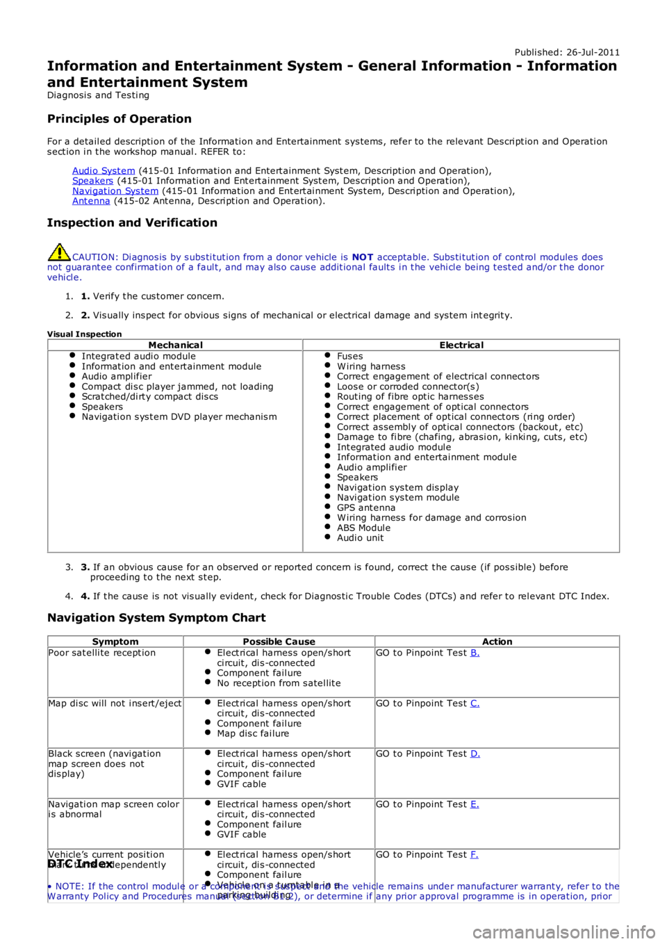
Navigation System Symptom Chart
SymptomPossible CauseActionPoor sat elli te recept ionEl ect ri cal harnes s open/s hortci rcuit , di s -connectedComponent fail ureNo recept ion from s atel lit e
GO t o Pinpoint Tes t B.
Map di sc will not i ns ert /ejectEl ect ri cal harnes s open/s hortci rcuit , di s -connectedComponent fail ureMap dis c fai lure
GO t o Pinpoint Tes t C.
Black s creen (navi gat ionmap screen does notdis play)
El ect ri cal harnes s open/s hortci rcuit , di s -connectedComponent fail ureGVIF cable
GO t o Pinpoint Tes t D.
Navigati on map s creen colori s abnormalEl ect ri cal harnes s open/s hortci rcuit , di s -connectedComponent fail ureGVIF cable
GO t o Pinpoint Tes t E.
Vehicle’s current posi ti onmark t urns independentl yEl ect ri cal harnes s open/s hortci rcuit , di s -connectedComponent fail ureVehicl e on a t urnt abl e i n aparki ng buildi ng
GO t o Pinpoint Tes t F.DTC Index
• NOTE: If the control modul e or a component i s s us pect and the vehicle remains under manufacturer warrant y, refer t o theW arranty Pol icy and Procedures manual (s ect ion B1.2), or determine i f any pri or approval programme is in operat ion, pri or
Page 1862 of 3229
1
1
2
3
1
1
1
2
3
1
2
3
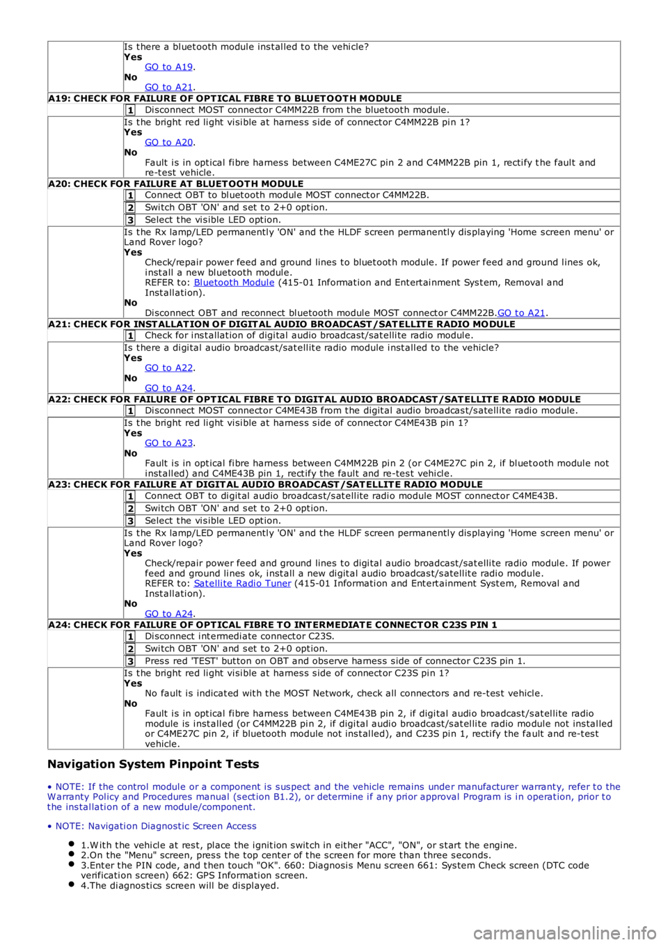
Is t here a bl uet ooth modul e ins t al led t o t he vehi cle?YesGO to A19.NoGO to A21.
A19: CHECK FOR FAILURE OF OPT ICAL FIBRE T O BLUET O OT H MODULE
Di sconnect MOST connect or C4MM22B from t he bluetoot h module.
Is t he bright red li ght vi si ble at harnes s s ide of connect or C4MM22B pi n 1?YesGO to A20.NoFault i s in opt ical fi bre harnes s between C4ME27C pin 2 and C4MM22B pin 1, recti fy the faul t andre-t est vehicle.
A20: CHECK FOR FAILURE AT BLUET OOT H MODULEConnect OBT to bl uet ooth modul e MOST connect or C4MM22B.
Swi tch OBT 'ON' and s et t o 2+0 opt ion.
Select t he vi s ible LED opt ion.
Is t he Rx lamp/LED permanentl y 'ON' and t he HLDF s creen permanentl y dis playing 'Home s creen menu' orLand Rover l ogo?YesCheck/repair power feed and ground lines t o bluet oot h module. If power feed and ground l ines ok,i nst all a new bl uetooth modul e.REFER t o: Bl uetooth Modul e (415-01 Informat ion and Ent ert ai nment Sys t em, Removal andInst all ati on).NoDi sconnect OBT and reconnect bl uetooth modul e MOST connect or C4MM22B.GO t o A21.
A21: CHECK FOR INST ALLAT ION O F DIGIT AL AUDIO BROADCAST /SAT ELLIT E RADIO MO DULECheck for i ns t allat ion of digi tal audio broadcast /sat elli te radio modul e.
Is t here a di gi tal audio broadcas t/sat ell it e radio module i nst all ed to the vehicle?YesGO to A22.NoGO to A24.
A22: CHECK FOR FAILURE OF OPT ICAL FIBRE T O DIGIT AL AUDIO BROADCAST /SAT ELLIT E R ADIO MODULEDi sconnect MOST connect or C4ME43B from t he digit al audio broadcas t/s atell it e radi o module.
Is t he bright red li ght vi si ble at harnes s s ide of connect or C4ME43B pin 1?YesGO to A23.NoFault i s in opt ical fi bre harnes s between C4MM22B pi n 2 (or C4ME27C pi n 2, if bl uet ooth modul e noti nst all ed) and C4ME43B pin 1, rect ify t he faul t and re-tes t vehi cl e.A23: CHECK FOR FAILURE AT DIGIT AL AUDIO BROADCAST /SAT ELLIT E RADIO MODULE
Connect OBT to di git al audio broadcas t/s at ell it e radi o module MOST connect or C4ME43B.
Swi tch OBT 'ON' and s et t o 2+0 opt ion.
Select t he vi s ible LED opt ion.
Is t he Rx lamp/LED permanentl y 'ON' and t he HLDF s creen permanentl y dis playing 'Home s creen menu' orLand Rover l ogo?YesCheck/repair power feed and ground lines t o digi tal audio broadcast /sat elli te radio modul e. If powerfeed and ground li nes ok, i nst all a new di git al audio broadcas t/s atell it e radi o module.REFER t o: Sat elli te Radi o Tuner (415-01 Informati on and Ent ert ainment Syst em, Removal andInst all ati on).NoGO to A24.A24: CHECK FOR FAILURE OF OPT ICAL FIBRE T O INT ERMEDIAT E CONNECT OR C23S PIN 1
Di sconnect i nt ermedi ate connect or C23S.
Swi tch OBT 'ON' and s et t o 2+0 opt ion.
Pres s red 'TEST' but ton on OBT and obs erve harnes s s ide of connector C23S pin 1.
Is t he bright red li ght vi si ble at harnes s s ide of connect or C23S pi n 1?YesNo fault i s indicat ed wit h t he MOST Net work, check all connectors and re-t es t vehicle.NoFault i s in opt ical fi bre harnes s between C4ME43B pin 2, if digi tal audi o broadcas t /s at el li te radiomodule is i nst all ed (or C4MM22B pi n 2, if digi tal audi o broadcast /s at el li te radio modul e not ins tal ledor C4ME27C pin 2, i f bluetooth module not ins t al led), and C23S pi n 1, recti fy the fault and re-t es tvehicle.
Navigation System Pinpoint Tests
• NOTE: If the control modul e or a component i s s us pect and the vehicle remains under manufacturer warrant y, refer t o theW arranty Pol icy and Procedures manual (s ect ion B1.2), or determine i f any pri or approval Program is i n operat ion, prior t ot he ins tal lati on of a new modul e/component.
• NOTE: Navigati on Diagnost ic Screen Access
1.W it h t he vehi cl e at res t , pl ace the i gnit ion s wit ch in eit her "ACC", "ON", or s t art t he engi ne.2.On the "Menu" screen, pres s t he t op cent er of t he s creen for more t han three s econds.3.Ent er t he PIN code, and t hen touch "OK". 660: Diagnosi s Menu s creen 661: Sys tem Check screen (DTC codeverificati on s creen) 662: GPS Informati on s creen.4.The di agnos ti cs screen will be di spl ayed.
Page 1863 of 3229
1
1
1
1
1
1
1
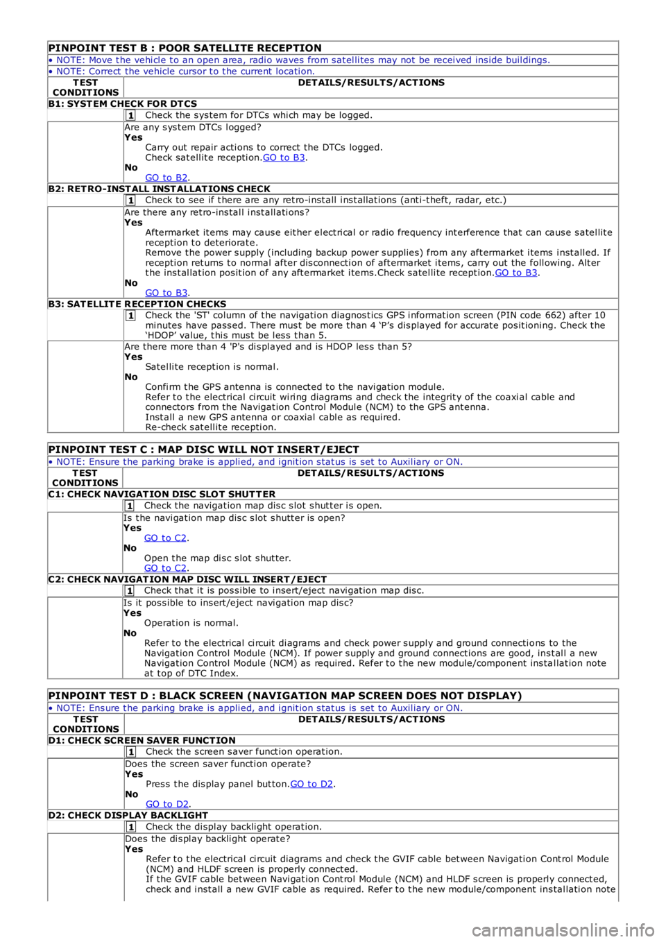
PINPOINT TEST B : POOR SATELLITE RECEPTION
• NOTE: Move t he vehi cl e t o an open area, radi o waves from s at el li tes may not be recei ved ins ide buil dings.
• NOTE: Correct the vehicle cursor t o t he current locati on.
T ESTCONDIT IONSDET AILS/RESULT S/ACT IONS
B1: SYST EM CHECK FOR DT CS
Check the s ys tem for DTCs whi ch may be logged.
Are any s ys t em DTCs l ogged?YesCarry out repair acti ons to correct the DTCs logged.Check sat ell it e recepti on.GO t o B3.NoGO to B2.
B2: RET RO-INST ALL INST ALLAT IONS CHECKCheck to see if t here are any ret ro-i nst all i ns t allat ions (ant i-t heft, radar, etc.)
Are there any ret ro-ins tal l i nst all ati ons ?YesAftermarket it ems may caus e eit her el ect ri cal or radio frequency int erference that can caus e s atel lit erecepti on t o deteriorat e.Remove t he power s upply (including backup power s upplies ) from any aft ermarket i tems i nst all ed. Ifrecepti on ret urns t o normal after dis connecti on of aft ermarket i tems , carry out the foll owing. Alt ert he ins t al lat ion pos it ion of any aft ermarket i tems.Check s atel li te recept ion.GO to B3.NoGO to B3.
B3: SAT ELLIT E R ECEPT ION CHECKSCheck the 'ST' column of t he navigati on diagnos t ics GPS i nformat ion screen (PIN code 662) after 10mi nutes have pass ed. There mus t be more t han 4 ‘P’s dis played for accurat e pos it ioning. Check t he‘HDOP’ value, t hi s mus t be l es s t han 5.
Are there more than 4 'P's di s pl ayed and is HDOP les s than 5?YesSatel li te recept ion i s normal .NoConfi rm t he GPS antenna is connect ed t o t he navi gat ion modul e.Refer t o t he electrical ci rcuit wi ri ng diagrams and check the integrit y of the coaxial cable andconnectors from the Navigat ion Control Modul e (NCM) to the GPS ant enna.Inst all a new GPS antenna or coaxial cabl e as requi red.Re-check s at ell it e recepti on.
PINPOINT TEST C : MAP DISC WILL NOT INSERT/EJECT
• NOTE: Ens ure t he parking brake is appli ed, and i gnit ion s tat us is set t o Auxil iary or ON.
T ESTCONDIT IONSDET AILS/RESULT S/ACT IONS
C1: CHECK NAVIGAT ION DISC SLO T SHUT T ER
Check the navigat ion map dis c s lot s hut t er i s open.
Is t he navi gat ion map dis c s lot s hutt er is open?YesGO t o C2.NoOpen t he map di s c s lot s hut ter.GO t o C2.
C2: CHECK NAVIGAT ION MAP DISC WILL INSERT /EJECTCheck that i t is pos s ible to i nsert/eject navi gat ion map dis c.
Is it pos s ible to ins ert /eject navi gati on map dis c?YesOperat ion is normal.NoRefer t o t he electrical ci rcuit di agrams and check power s uppl y and ground connecti ons to theNavigat ion Control Modul e (NCM). If power s upply and ground connect ions are good, ins t al l a newNavigat ion Control Modul e (NCM) as required. Refer t o t he new module/component ins tal lat ion noteat t op of DTC Index.
PINPOINT TEST D : BLACK SCREEN (NAVIGATION MAP SCREEN DOES NOT DISPLAY)
• NOTE: Ens ure t he parking brake is appli ed, and i gnit ion s tat us is set t o Auxil iary or ON.
T ESTCONDIT IONSDET AILS/RESULT S/ACT IONS
D1: CHECK SCREEN SAVER FUNCT IONCheck the s creen s aver funct ion operat ion.
Does the screen saver functi on operate?YesPres s t he dis play panel but ton.GO t o D2.NoGO to D2.
D2: CHECK DISPLAY BACKLIGHT
Check the di spl ay backli ght operat ion.
Does the di s pl ay backli ght operat e?YesRefer t o t he electrical ci rcuit diagrams and check t he GVIF cable bet ween Navigati on Cont rol Module(NCM) and HLDF s creen is properly connect ed.If the GVIF cable bet ween Navi gat ion Cont rol Modul e (NCM) and HLDF s creen is properly connect ed,check and i nst all a new GVIF cable as required. Refer t o t he new module/component ins tal lati on note
Page 1864 of 3229
1
1
1
1
1
1
at t op of DTC Index.If the GVIF cable bet ween Navi gat ion Cont rol Modul e (NCM) and HLDF s creen is properly connect edand NOT damaged, check and i nst all a new Navi gat ion Cont rol Module (NCM) as required. Refer tot he new module/component ins tal lati on note at t op of DTC Index.Re-check the s ys tem.NoCheck the HLDF di spl ay.Re-check the s ys tem.
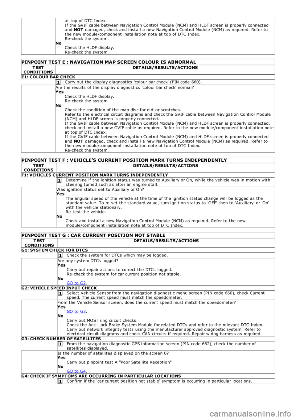
PINPOINT TEST E : NAVIGATION MAP SCREEN COLOUR IS ABNORMAL
T ESTCONDIT IONSDET AILS/RESULT S/ACT IONS
E1: COLOUR BAR CHECK
Carry out the di s pl ay diagnost ics 'colour bar check' (PIN code 660).
Are the res ul ts of t he dis play di agnos ti cs 'colour bar check' normal ?YesCheck the HLDF di spl ay.Re-check the s ys tem.NoCheck the condit ion of t he map dis c for di rt or s crat ches .Refer t o t he electrical ci rcuit diagrams and check t he GVIF cable bet ween Navigati on Cont rol Module(NCM) and HLDF s creen is properly connect ed.If the GVIF cable bet ween Navi gat ion Cont rol Modul e (NCM) and HLDF s creen is properly connect ed,check and i nst all a new GVIF cable as required. Refer t o t he new module/component ins tal lati on noteat t op of DTC Index.If the GVIF cable bet ween Navi gat ion Cont rol Modul e (NCM) and HLDF s creen is properly connect edand NOT damaged, check and i nst all a new Navi gat ion Cont rol Module (NCM) as required. Refer tot he new module/component ins tal lati on note at t op of DTC Index.Re-check the s ys tem.
PINPOINT TEST F : VEHICLE’S CURRENT POSITION MARK TURNS INDEPENDENTLY
T ESTCONDIT IONSDET AILS/RESULT S/ACT IONS
F1: VEHICLES CURRENT POSIT ION MARK T URNS INDEPENDENT LY
Det ermi ne if t he ignit ion st atus was turned to Auxil iary or On, whi le the vehicle was in moti on wit hs t eering t urned s uch as aft er an engi ne s tall .
W as ignit ion s t at us s et to Auxi liary or On?YesThe angular s peed of t he vehi cl e at t he ti me of t he igni ti on st atus change wil l be logged as t hes t andard val ue. To re-s et t he s tandard value, t urn i gni ti on s tat us to 'OFF' t hen t o 'Auxil iary' or 'On'wi th the vehicle st ati onary.Re-tes t the vehicle.NoCheck and ins tal l a new Navigati on Cont rol Module (NCM) as requi red. Refer t o t he newmodule/component ins tal lati on note at top of DTC Index.
PINPOINT TEST G : CAR CURRENT POSITION NOT STABLE
T ESTCONDIT IONSDET AILS/RESULT S/ACT IONS
G1: SYST EM CHECK FOR DT CS
Check the sys tem for DTCs whi ch may be l ogged.
Are any s ys t em DTCs l ogged?YesCarry out repair act ions to correct the DTCs logged.Re-check the sys tem for car current pos it ion not s table.NoGO to G2.
G2: VEHICLE SPEED INPUT CHECK
Select Vehicle Sens or from t he navi gat ion di agnos ti c menu s creen (PIN code 660), check Currents peed. The current speed mus t mat ch the speedometer.
From t he Vehi cl e Sensor s creen, does t he current s peed mus t mat ch the s peedomet er?YesGO to G3.NoCarry out MOST ring ci rcuit checks .Check the Ant i-Lock Brake Sys t em Module for rel at ed DTCs and refer to the relevant DTC Index.Carry out network int egrit y t est s us ing t he manufacturer approved di agnos ti c s ys t em. Refer toel ect ri cal circuit di agrams and check CAN circuit s i f required. Repair wi ring harness as required.
G3: CHECK NUMBER OF SAT ELLIT ES
From t he navi gat ion di agnos ti c GPS i nformat ion screen (PIN code 662), check t he number ofs atel li tes dis played.
Is t he number of s atel lit es dis played on t he s creen 0?YesCarry out pinpoint t est A "Poor Satell it e Recept ion"NoGO to G4.G4: CHECK IF SYMPT OMS ARE OCCURRING IN PART ICULAR LOCAT IO NS
Confi rm if t he 'car current pos it ion not s table' s ymptom is occurring i n part icular locati ons .
Page 1865 of 3229
1
1
1
1
1
1
1
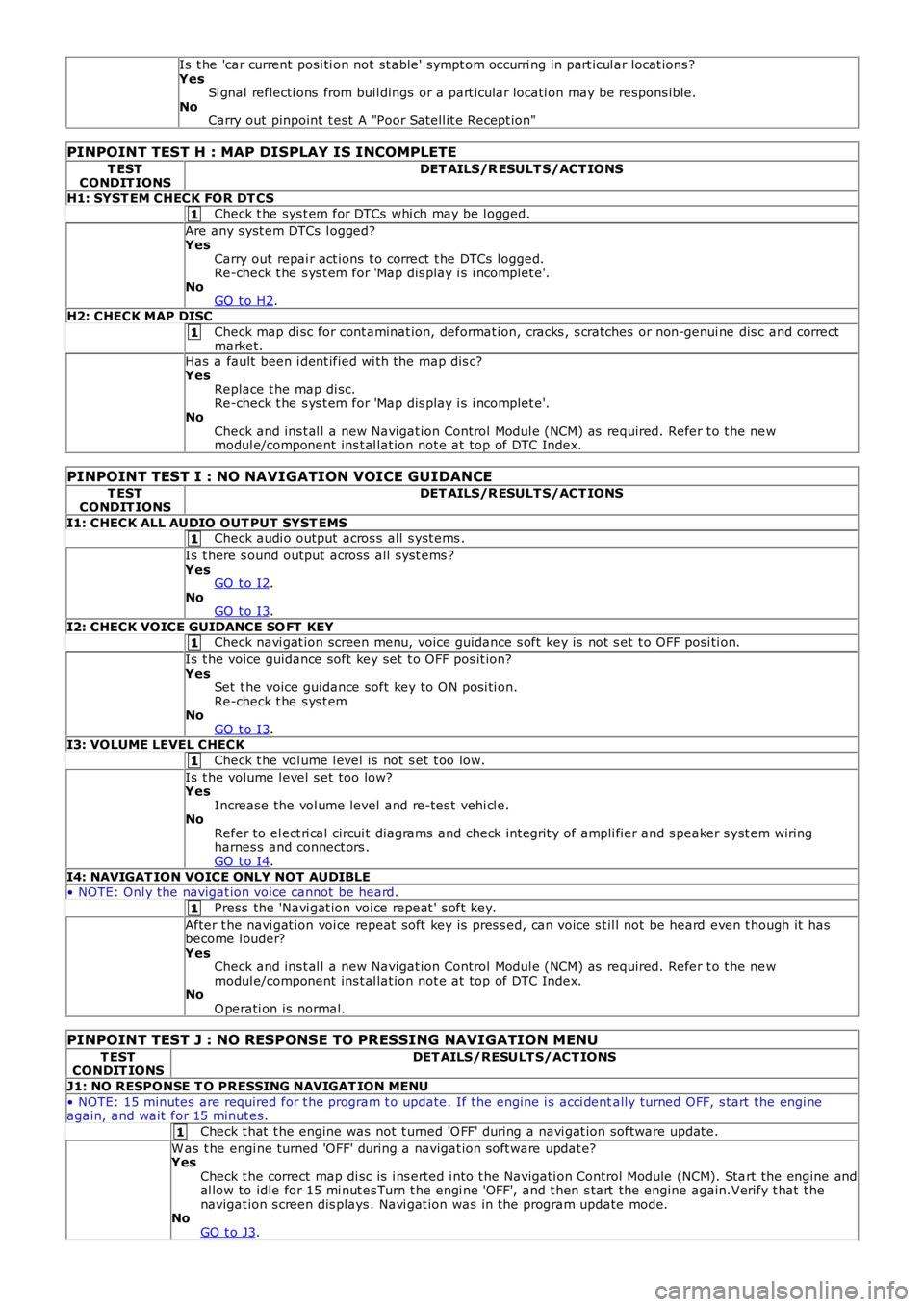
Is t he 'car current posi ti on not st able' sympt om occurri ng in part icul ar locat ions ?YesSi gnal reflecti ons from buil dings or a part icular locati on may be respons ible.NoCarry out pinpoint t est A "Poor Satell it e Recept ion"
PINPOINT TEST H : MAP DISPLAY IS INCOMPLETE
T ESTCONDIT IONSDET AILS/R ESULT S/ACT IONS
H1: SYST EM CHECK FOR DT CSCheck t he sys t em for DTCs whi ch may be l ogged.
Are any s yst em DTCs l ogged?YesCarry out repai r act ions t o correct t he DTCs logged.Re-check t he s ys t em for 'Map dis play i s i ncomplet e'.NoGO t o H2.H2: CHECK MAP DISC
Check map di sc for cont aminat ion, deformat ion, cracks , s cratches or non-genui ne dis c and correctmarket.Has a fault been i dent ified wi th the map dis c?YesReplace t he map di sc.Re-check t he s ys t em for 'Map dis play i s i ncomplet e'.NoCheck and ins t al l a new Navigat ion Control Modul e (NCM) as required. Refer t o t he newmodul e/component ins t al lat ion not e at top of DTC Index.
PINPOINT TEST I : NO NAVIGATION VOICE GUIDANCE
T ESTCONDIT IONSDET AILS/R ESULT S/ACT IONS
I1: CHECK ALL AUDIO OUT PUT SYST EMSCheck audi o output acros s all s yst ems .
Is t here s ound output across all s ys t ems ?YesGO t o I2.NoGO t o I3.
I2: CHECK VOICE GUIDANCE SO FT KEYCheck navi gat ion screen menu, voice guidance s oft key is not s et t o OFF posi ti on.
Is t he voice guidance soft key set t o OFF pos it ion?YesSet t he voice guidance soft key to O N posi ti on.Re-check t he s ys t emNoGO t o I3.I3: VOLUME LEVEL CHECK
Check t he vol ume l evel is not s et t oo low.
Is t he volume l evel s et too low?YesIncrease the vol ume level and re-tes t vehi cl e.NoRefer to el ect ri cal circui t diagrams and check int egrit y of ampli fier and s peaker s yst em wiringharnes s and connect ors .GO t o I4.
I4: NAVIGAT ION VOICE ONLY NOT AUDIBLE• NOTE: Onl y the navigat ion voice cannot be heard.
Press the 'Navi gat ion voi ce repeat ' s oft key.
After t he navi gat ion voi ce repeat soft key is pres s ed, can voice s t il l not be heard even t hough it hasbecome l ouder?YesCheck and ins t al l a new Navigat ion Control Modul e (NCM) as required. Refer t o t he newmodul e/component ins t al lat ion not e at top of DTC Index.NoO perati on is normal.
PINPOINT TEST J : NO RESPONSE TO PRESSING NAVIGATION MENU
T ESTCONDIT IONSDET AILS/RESULT S/ACT IONS
J1: NO RESPONSE T O PRESSING NAVIGAT ION MENU
• NOTE: 15 minutes are required for t he program t o update. If the engine i s acci dentally turned OFF, s tart the engi neagain, and wait for 15 minut es.
Check t hat t he engine was not t urned 'O FF' during a navi gat ion software updat e.
W as t he engi ne turned 'OFF' during a navigat ion s oft ware updat e?YesCheck t he correct map di sc is i ns erted i nto t he Navigati on Control Module (NCM). Start the engine andal low to idle for 15 mi nut es Turn t he engi ne 'OFF', and t hen s tart the engine again.Verify t hat t henavigat ion s creen dis plays . Navi gat ion was in the program update mode.NoGO t o J3.
Page 1889 of 3229
Publi s hed: 11-May-2011
Information and Entertainment System - Navigation System
Des cript ion and Operat ion
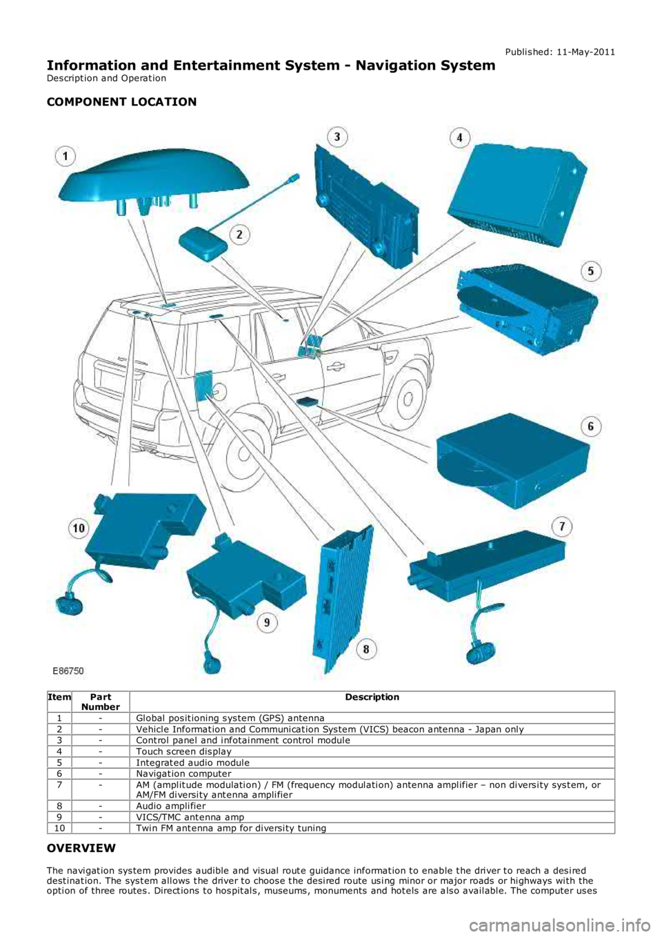
COMPONENT LOCATION
ItemPartNumberDescription
1-Gl obal pos it ioning s ys tem (GPS) antenna
2-Vehicl e Informat ion and Communi cat ion Sys tem (VICS) beacon antenna - Japan onl y3-Cont rol panel and i nfotai nment control modul e
4-Touch s creen dis play
5-Integrat ed audio modul e6-Navigat ion computer
7-AM (ampl it ude modulati on) / FM (frequency modul ati on) ant enna ampl ifier – non di versi ty sys t em, orAM/FM di versi ty ant enna ampli fier
8-Audio ampli fier
9-VICS/TMC ant enna amp10-Twi n FM ant enna amp for di versi ty tuning
OVERVIEW
The navi gat ion sys tem provides audible and vis ual rout e guidance informat ion t o enable t he dri ver t o reach a des i reddest inat ion. The sys t em all ows t he driver t o choos e t he desi red route us i ng minor or major roads or hi ghways wi th theopti on of three routes . Direct ions t o hos pit al s , museums , monuments and hot els are als o avail abl e. The computer us es
Page 1890 of 3229
map i nformati on st ored on a DVD t o det ermi ne the bes t rout e for t he journey and provide t he dri ver wi th det ail s ofdirect ions and approachi ng juncti ons .
The navi gat ion sys tem is cont roll ed by t he dri ver from the t ouch screen di s pl ay. Cont rol s ignals from the touch s creendis play are s ent on the Medi a Ori entat ed Sys t em Trans port (MOST) ri ng to the i nfot ainment cont rol module where t hey aret hen trans mi tt ed on t he MOST ring t o t he navi gati on comput er. The navi gati on comput er us es a dedicat ed Gigabit VideoInt erface (GVIF) to t rans mi t vi deo s ignals t o t he touch s creen dis play.
Vehicles wi th navigat ion s yst ems al so incorporat e addi ti onal t raffi c informati on s yst ems . Thes e are market dependant andare as foll ows :
Europe - Traffi c Mes sage Channel (TMC).Japan - Vehicl e Informat ion and Communi cat ion Sys tem (VICS).NAS - No addi ti onal s ys t em.
Navigation Computer
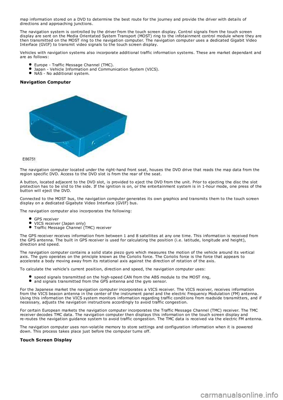
The navi gat ion comput er l ocat ed under t he right-hand front s eat, hous es the DVD dri ve that reads t he map dat a from theregi on specific DVD. Acces s t o t he DVD s l ot i s from the rear of t he s eat.
A but ton, located adjacent to the DVD s lot, i s provided t o eject t he DVD from t he uni t. Prior t o ejecti ng t he dis c the sl otprot ect ion has t o be s l id t o t he s ide. If t he i gni ti on is on, or t he ent ert ainment sys t em i s in 1-hour mode, one press of t hebutt on wil l eject the DVD.
Connected to the MOST bus , t he navi gat ion computer generat es it s own graphics and t rans mit s t hem t o t he t ouch s creendis play on a dedi cat ed Gigabyte Vi deo Int erface (GVIF) bus .
The navi gat ion comput er al so incorporat es the foll owing:
GPS receiverVICS receiver (Japan onl y)Traffi c Mess age Channel (TMC) recei ver
The GPS receiver receives informat ion from between 1 and 8 s atell it es at any one ti me. Thi s i nformat ion i s received fromt he GPS antenna. The bui lt in GPS receiver is us ed for calculat ing t he pos it ion (i.e. l ati tude, longit ude and hei ght ),direct ion and s peed.
The navi gat ion comput er contai ns a s olid s tat e piezo gyro whi ch measures the moti on of the vehicle around it s vert icalaxis . The gyro operat es on the principle known as the Corioli s force. The Corioli s force is t he force t hat appears t oaccelerate a body movi ng away from it s rot ati onal axis agains t the di recti on of rot ati on of the axis .
To calculate the vehicle's current posi ti on, di recti on and s peed, t he navi gat ion computer us es:
s peed si gnal s transmit ted on the hi gh-s peed CAN from t he ABS module to the MO ST ri ng,and s ignals t rans mit t ed from t he GPS ant enna and t he gyro sens or.
For the Japanes e market t he navigati on comput er incorporates a VICS recei ver. The VICS receiver, receives i nformat ionfrom the VICS beacon ant enna i n t he cent er of the i nst rument panel and t he elect ric Frequency Modulati on (FM) ant enna.Us ing t his i nformati on the VICS s yst em monit ors i nformat ion regarding t raffi c conditions from roads ide t rans mit t ers , and ifneces s ary, adjust s t he navi gati on ins truct ions accordingly t o avoid t raffi c conges tion.
For certain European markets the navigati on comput er incorporat es the Traffic Mes s age Channel (TMC) receiver. The TMCreceiver decodes TMC data. The navigati on comput er then di spl ays t his informati on on t he touch s creen dis play andre-rout es the navigat ion guidance sys t em t o avoi d t raffi c congest ion. The TMC dat a is received via t he electric FM antenna.
The navi gat ion comput er us es non-volat ile memory to st ore set ti ngs and configurat ion i nformat ion when it is powereddown. Thi s process takes place jus t before the comput er t urns off.
Touch Screen Display