Page 1796 of 3383
DTC P2A00, P2A03 A/F SENSOR 1EC-585
C
DE
F
G H
I
J
K L
M A
EC
Revision: November 2009 2006 QX56
11 . REPLACE AIR FUEL RATIO (A/F) SENSOR 1
Replace air fuel ratio (A/F) sensor 1.
CAUTION:
�Discard any A/F sensor which has been dropped from a height of more than 0.5 m (19.7 in) onto a
hard surface such as a concrete floor; use a new one.
�Before installing new A/F sensor, clean exhaust system threads using Oxygen Sensor Thread
Cleaner tool J-43897-18 or J-43897-12 and approved anti-seize lubricant.
>>INSPECTION END
Removal and InstallationUBS00N7J
AIR FUEL RATIO (A/F) SENSOR 1
Refer to EM-21, "EXHAUST MANIFOLD AND THREE WAY CATALYST" .
Page 1815 of 3383
EC-604Revision: November 2009
FUEL PUMP
2006 QX56
FUEL PUMPPFP:17042
DescriptionUBS00HDB
SYSTEM DESCRIPTION
*: ECM determines the start signal status by the signals of engine speed and battery voltage.
The ECM activates the fuel pump for several seconds after the ignition switch is turned ON to improve engine
startability. If the ECM receives a engine speed signal from the camshaft position sensor (PHASE), it knows
that the engine is rotating, and causes the pump to operate. If the engine speed signal is not received when
the ignition switch is ON, the engine stalls. The ECM stops pump operation and prevents battery discharging,
thereby improving safety. The ECM does not directly drive the fuel pump. It controls the ON/OFF fuel pump
relay, which in turn controls the fuel pump.
COMPONENT DESCRIPTION
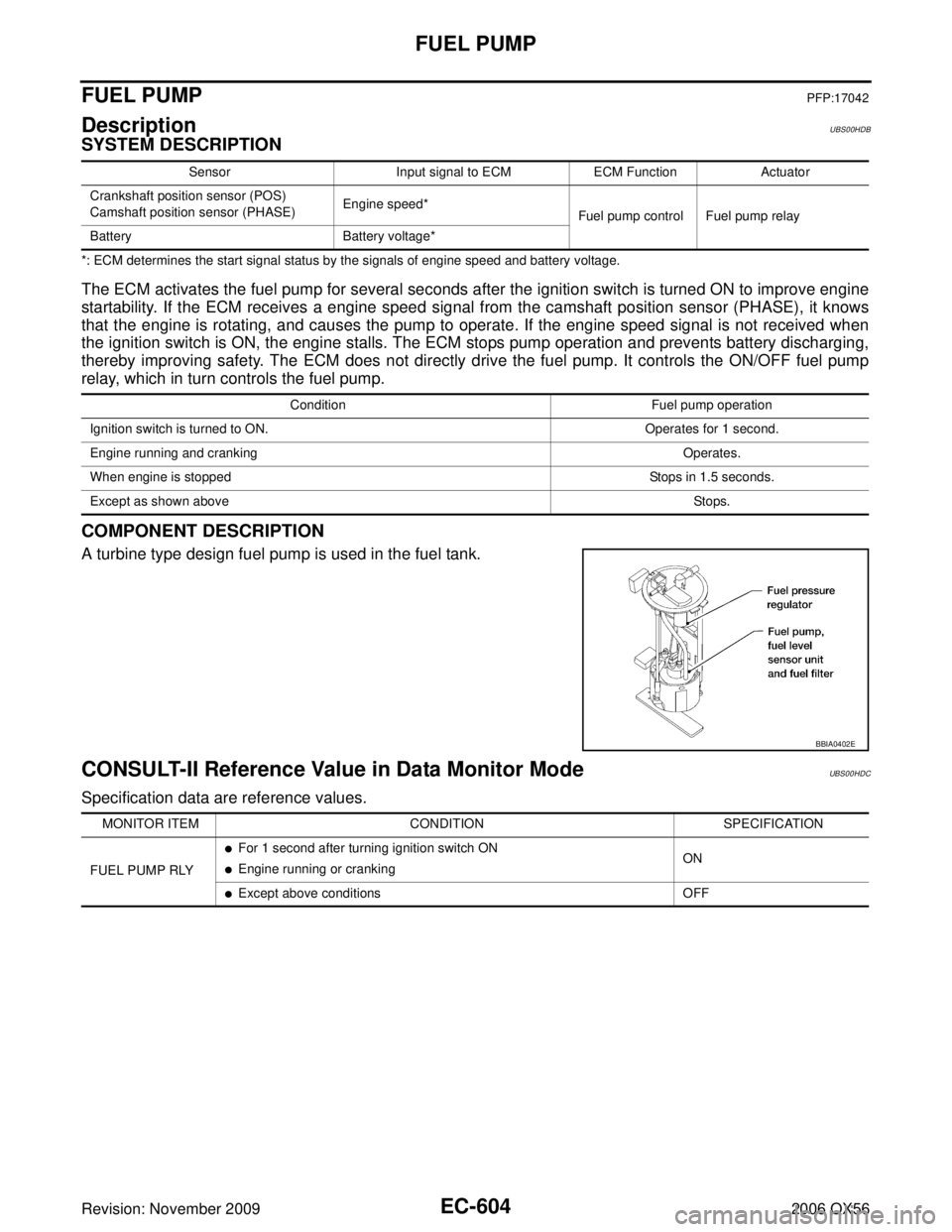
A turbine type design fuel pump is used in the fuel tank.
CONSULT-II Reference Value in Data Monitor ModeUBS00HDC
Specification data are reference values.
SensorInput signal to ECMECM FunctionActuator
Crankshaft position sensor (POS)
Camshaft position sensor (PHASE) Engine speed*
Fuel pump control Fuel pump relay
Battery Battery voltage*
Condition Fuel pump operation
Ignition switch is turned to ON. Operates for 1 second.
Engine running and cranking Operates.
When engine is stopped Stops in 1.5 seconds.
Except as shown above Sto ps.
BBIA0402E
MONITOR ITEMCONDITION SPECIFICATION
FUEL PUMP RLY
�For 1 second after turning ignition switch ON
�Engine running or cranking ON
�Except above conditions
OFF
Page 1819 of 3383
EC-608Revision: November 2009
FUEL PUMP
2006 QX56
7. CHECK CONDENSER-2 POWER SUPPLY CIRCUIT-II FOR OPEN AND SHORT
1. Disconnect IPDM E/R harness connector E119.
2. Check harness continuity between IPDM E/R terminal 13 and condenser-2 terminal 1. Refer to Wiring Diagram.
3. Also check harness for short to ground and short to power.
OK or NG
OK >> GO TO 13.
NG >> Repair open circuit or short to ground or short to power in harness or connectors.
8. CHECK CONDENSER-2 GROUND CIRCUIT FOR OPEN AND SHORT
1. Check harness continuity between condenser-2
+ terminal 2 and ground.
Refer to Wiring Diagram.
2. Also check harness for short to power.
OK or NG
OK >> GO TO 9.
NG >> Repair open circuit or short to power in harness or connectors.
9. CHECK CONDENSER-2
Refer to EC-609, "
Component Inspection" .
OK or NG
OK >> GO TO 10.
NG >> Replace condenser-2.
10. CHECK FUEL PUMP POWER SUPPLY AND GROUND CIRCUIT FOR OPEN AND SHORT
1. Turn ignition switch OFF.
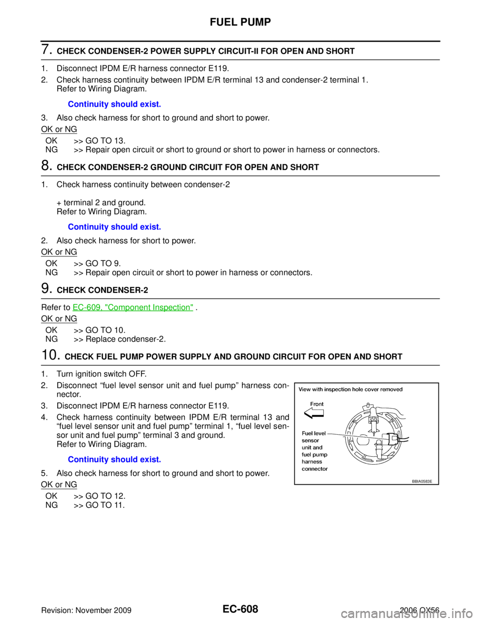
2. Disconnect “fuel level sensor unit and fuel pump ” harness con-
nector.
3. Disconnect IPDM E/R harness connector E119.
4. Check harness continuity between IPDM E/R terminal 13 and “fuel level sensor unit and fuel pump” terminal 1, “fuel level sen-
sor unit and fuel pump ” terminal 3 and ground.
Refer to Wiring Diagram.
5. Also check harness for short to ground and short to power.
OK or NG
OK >> GO TO 12.
NG >> GO TO 11. Continuity should exist.
Continuity should exist.
Continuity should exist.
BBIA0583E
Page 1820 of 3383
FUEL PUMPEC-609
C
DE
F
G H
I
J
K L
M A
EC
Revision: November 2009 2006 QX56
11 . DETECT MALFUNCTIONING PART
Check the following.
�Harness connectors E41, C1
�Harness for open or short between fuel pump and IPDM E/R
�Harness for open or short between fuel pump and ground
>> Repair open circuit or short to ground or short to power in harness or connectors.
12. CHECK FUEL PUMP
Refer to EC-609, "
Component Inspection" .
OK or NG
OK >> GO TO 13.
NG >> Replace “fuel level sensor unit and fuel pump ”.
13. CHECK INTERMITTENT INCIDENT
Refer to EC-144, "
TROUBLE DIAGNOSIS FOR INTERMITTENT INCIDENT" .
OK or NG
OK >> Replace IPDM E/R.
NG >> Repair or replace harness or connectors.
Component InspectionUBS00HDF
FUEL PUMP
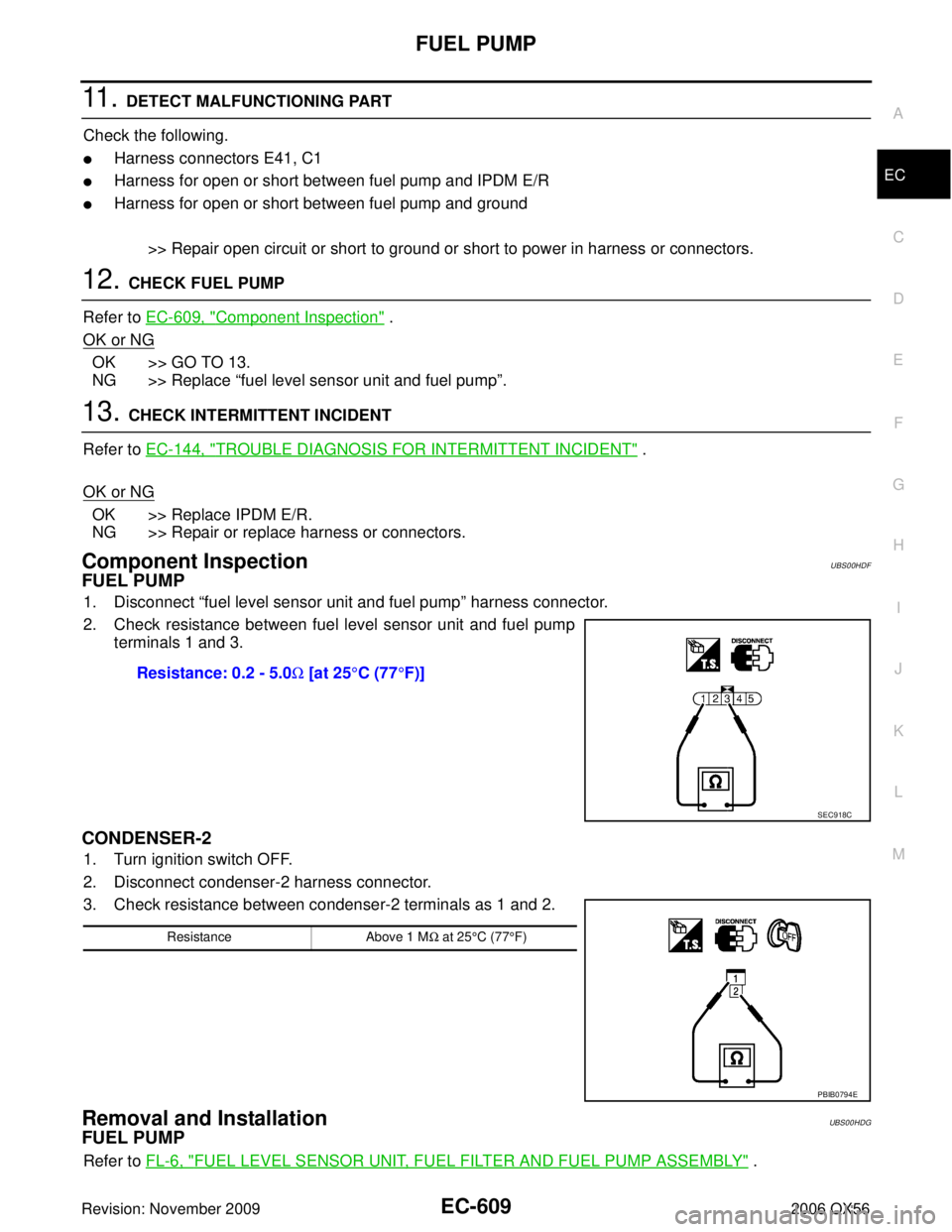
1. Disconnect “fuel level sensor unit and fuel pump ” harness connector.
2. Check resistance between fuel level sensor unit and fuel pump terminals 1 and 3.
CONDENSER-2
1. Turn ignition switch OFF.
2. Disconnect condenser-2 harness connector.
3. Check resistance between condenser-2 terminals as 1 and 2.
Removal and InstallationUBS00HDG
FUEL PUMP
Refer to FL-6, "FUEL LEVEL SENSOR UNIT, FUEL FILTER AND FUEL PUMP ASSEMBLY" .
Resistance: 0.2 - 5.0
Ω [at 25 °C (77 °F)]
SEC918C
Resistance Above 1 MΩ at 25 °C (77 °F)
PBIB0794E
Page 1841 of 3383
EC-630Revision: November 2009
REFRIGERANT PRESSURE SENSOR
2006 QX56
REFRIGERANT PRESSURE SENSORPFP:92136
Component DescriptionUBS00HDH
The refrigerant pressure sensor is installed at the condenser of the
air conditioner system. The sensor uses an electrostatic volume
pressure transducer to convert refrigerant pressure to voltage. The
voltage signal is sent to ECM, and ECM controls cooling fan system.
BBIA0445E
PBIB2657E
Page 1842 of 3383
REFRIGERANT PRESSURE SENSOREC-631
C
DE
F
G H
I
J
K L
M A
EC
Revision: November 2009 2006 QX56
Wiring DiagramUBS00HDI
BBWA1715E
Page 1843 of 3383
EC-632Revision: November 2009
REFRIGERANT PRESSURE SENSOR
2006 QX56
Specification data are reference values and are measured between each terminal and ground.
CAUTION:
Do not use ECM ground terminals when measuring input/output voltage. Doing so may result in dam-
age to the ECM's transistor. Use a ground other than ECM terminals, such as the ground.
Diagnostic ProcedureUBS00HDJ
1. CHECK REFRIGERANT PRESSURE SENSOR OVERALL FUNCTION
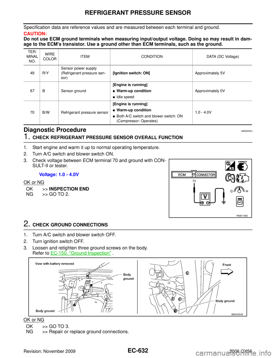
1. Start engine and warm it up to normal operating temperature.
2. Turn A/C switch and blower switch ON.
3. Check voltage between ECM terminal 70 and ground with CON- SULT-II or tester.
OK or NG
OK >> INSPECTION END
NG >> GO TO 2.
2. CHECK GROUND CONNECTIONS
1. Turn A/C switch and blower switch OFF.
2. Turn ignition switch OFF.
3. Loosen and retighten three ground screws on the body. Refer to EC-150, "
Ground Inspection" .
OK or NG
OK >> GO TO 3.
NG >> Repair or replace ground connections.
TER-
MINAL NO. WIRE
COLOR ITEM
CONDITION DATA (DC Voltage)
49 R/Y Sensor power supply
(Refrigerant pressure sen-
sor)
[Ignition switch: ON]
Approximately 5V
67 B Sensor ground [Engine is running]
�Warm-up condition
�Idle speedApproximately 0V
70 B/W Refrigerant pressure sensor [Engine is running]
�Warm-up condition
�Both A/C switch and blower switch: ON
(Compressor: Operates)1.0 - 4.0V
Voltage: 1.0 - 4.0V
PBIB1188E
BBIA0354E
Page 1844 of 3383
REFRIGERANT PRESSURE SENSOREC-633
C
DE
F
G H
I
J
K L
M A
EC
Revision: November 2009 2006 QX56
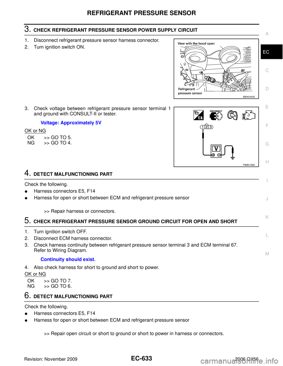
3. CHECK REFRIGERANT PRESSURE SENSOR POWER SUPPLY CIRCUIT
1. Disconnect refrigerant pressure sensor harness connector.
2. Turn ignition switch ON.
3. Check voltage between refrigerant pressure sensor terminal 1 and ground with CONSULT-II or tester.
OK or NG
OK >> GO TO 5.
NG >> GO TO 4.
4. DETECT MALFUNCTIONING PART
Check the following.
�Harness connectors E5, F14
�Harness for open or short between ECM and refrigerant pressure sensor
>> Repair harness or connectors.
5. CHECK REFRIGERANT PRESSURE SENSOR GROUND CIRCUIT FOR OPEN AND SHORT
1. Turn ignition switch OFF.
2. Disconnect ECM harness connector.
3. Check harness continuity between refrigerant pressure sensor terminal 3 and ECM terminal 67. Refer to Wiring Diagram.
4. Also check harness for short to ground and short to power.
OK or NG
OK >> GO TO 7.
NG >> GO TO 6.
6. DETECT MALFUNCTIONING PART
Check the following.
�Harness connectors E5, F14
�Harness for open or short between ECM and refrigerant pressure sensor
>> Repair open circuit or short to ground or short to power in harness or connectors.
BBIA0445E
Voltage: Approximately 5V
PBIB0188E
Continuity should exist.