Page 1914 of 3383
EXHAUST MANIFOLD AND THREE WAY CATALYSTEM-23
C
DE
F
G H
I
J
K L
M A
EM
Revision: November 2009 2006 QX56
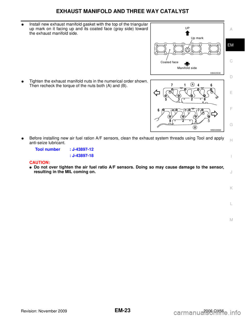
�Install new exhaust manifold gasket with the top of the triangular
up mark on it facing up and its coated face (gray side) toward
the exhaust manifold side.
�Tighten the exhaust manifold nuts in the numerical order shown.
Then recheck the torque of the nuts both (A) and (B).
�Before installing new air fuel ration A/F sensors, clean the exhaust system threads using Tool and apply
anti-seize lubricant.
CAUTION:
�Do not over tighten the air fuel ratio A/F sensors. Doing so may cause damage to the sensor,
resulting in the MIL coming on.
KBIA2553E
WBIA0696E
Tool number : J-43897-12
: J-43897-18
Page 1915 of 3383
EM-24Revision: November 2009
OIL PAN AND OIL STRAINER
2006 QX56
OIL PAN AND OIL STRAINERP F P : 1111 0
Removal and InstallationEBS00RF2
REMOVAL
WARNING:
To avoid the danger of being scalded, never drain the engine oil when the engine is hot.
1. Remove the engine. Refer to EM-74, "
REMOVAL" .
2. Remove the oil pan (lower) using the following steps.
a. Remove the oil pan (lower) bolts using power tool.
1. Oil pan (upper) 2. O-ring3. O-ring
4. O-ring 5. O-ring (with collar)6. Oil level gauge guide
7. Oil level gauge 8. O-ring9. Connector bolt
10. Oil filter 11. Oil cooler12. Relief valve
13. Oil pressure sensor 14. Gasket15. Drain plug
16. Oil pan (lower) 17. Oil strainer
KBIA2465E
KBIA2466E
Page 1937 of 3383
EM-46Revision: November 2009
CAMSHAFT
2006 QX56
CAMSHAFTPFP:13001
Removal and InstallationEBS00RF8
* Refer to GI-46, "Recommended Chemical Products and Sealants" .
REMOVAL
1. Remove the RH bank and LH bank rocker covers. Refer to EM-35, "Removal and Installation" .
2. Obtain compression TDC of No. 1 cylinder as follows:
a. Turn the crankshaft pulley clockwise to align the TDC identifica- tion notch (without paint mark) with the timing indicator on the
front cover.
1. Cylinder head (RH bank) 2. Camshaft bracket (No. 2, 3, 4, 5) 3. Valve lifter
4. Camshaft bracket (No. 1) 5. Seal washer6. Camshaft (RH bank EXH)
7. Camshaft (RH bank INT) 8. Camshaft (LH bank INT)9. Camshaft (LH bank EXH)
10. Camshaft sprocket (RH bank EXH) 11. Camshaft sprocket (RH bank INT) 12. Camshaft sprocket (LH bank INT)
13. Camshaft sprocket (LH bank EXH) 14. Camshaft position sensor (PHASE) 15. O-ring
16. Cylinder head (LH bank)
WBIA0469E
KBIA2476E
Page 1955 of 3383

EM-64Revision: November 2009
CYLINDER HEAD
2006 QX56
Removal and InstallationEBS00RFE
REMOVAL
1. Remove the engine assembly from the vehicle. Refer to EM-74, "Removal and Installation" .
2. Remove the following components and related parts:
�Drive belt auto tensioner drive belts and idler pulley. Refer to EM-14, "REMOVAL" .
�Thermostat housing and hose. Refer to CO-21, "Removal and Installation" .
�Oil pan and oil strainer. Refer to EM-24, "Removal and Installation" .
�Fuel tube and fuel injector assembly. Refer to EM-31, "Removal and Installation" .
�Intake manifold. Refer to EM-17, "Removal and Installation" .
�Ignition coil. Refer to EM-28, "Removal and Installation" .
�Rocker cover. Refer to EM-35, "Removal and Installation" .
3. Remove the crankshaft pulley, front cover, oil pump, and timing chain. Refer to EM-37, "
Removal and
Installation" .
4. Remove the camshaft sprockets and camshafts. Refer to EM-46, "
Removal and Installation" .
5. Remove the cylinder head bolts in reverse of order shown.
1. Harness bracket 2. Engine coolant temperature sensor 3. Washer
4. Cylinder head gasket (LH) 5. Cylinder head (RH) 6. Cylinder head bolt
7. Cylinder head gasket (RH) 8. Cylinder head (LH)
KBIA2528E
PBIC0068E
Page 1970 of 3383

CYLINDER BLOCKEM-79
C
DE
F
G H
I
J
K L
M A
EM
Revision: November 2009 2006 QX56
* Refer to GI-46, "Recommended Chemical Products and Sealants" .
DISASSEMBLY
NOTE:
Explained here is how to disassemble with engine stand supporting transmission surface. When using differ-
ent type of engine stand, some steps may be different.
1. Remove engine assembly and mount to engine stand. Refer to EM-74, "
Removal and Installation" .
CAUTION:
Before removing the hanging chains, make sure engine stand is stable and there is no risk of over-
turning.
2. Drain engine oil. Refer to LU-8, "
Changing Engine Oil" .
3. Drain engine coolant by removing the cylinder block drain plugs “A”, “B ”, “C” and “D ” as shown.
4. Remove the following components and associated parts (the parts referred to in step 1 are not included here).
�Oil pan (upper and lower) and oil strainer. Refer to EM-24, "Removal and Installation" .
�Crankshaft pulley, front cover and timing chain. Refer to EM-37, "Removal and Installation" .
�Camshaft. Refer to EM-46, "Removal and Installation" .
�Cylinder head. Refer to EM-64, "Removal and Installation" .
5. Remove knock sensor and sub harness.
CAUTION:
Carefully handle sensor, avoiding shocks.
6. Check connecting rod side clearance. Refer to EM-94, "
CONNECTING ROD SIDE CLEARANCE" .
7. Remove piston and connecting rod assembly as follows.
a. Position the crankshaft pin corresponding to the connecting rod to be removed onto bottom dead center.
1. Knock sensor sub-harness 2. Knock sensor 3. Cylinder block
4. Main bearing upper 5. Top ring 6. Second ring
7. Oil ring 8. Crankshaft key 9. Piston
10. Connecting rod 11. Snap ring 12. Piston pin
13. Connecting rod bearing 14. Connecting rod bearing cap 15. Main bearing cap
16. Thrust bearing lower 17. Main bearing lower 18. Crankshaft
19. Pilot converter 20. Thrust bearing upper 21. Side bolt
22. Drive plate 23. Reinforcement plate 24. Rear oil seal retainer
25. Rear oil seal 26. Transmission 27. O-ring
28. Crankshaft position sensor (POS) 29. Gasket 30. Cylinder block heater
31. Connector cap
WBIA0419E
KBIA2549E
Page 1977 of 3383

EM-86Revision: November 2009
CYLINDER BLOCK
2006 QX56
15. Tighten connecting rod bolts using Tool.
�Apply engine oil to threads and seats of connecting rod bolts.
�After tightening bolts, make sure the crankshaft rotates
smoothly.
�Check connecting rod side clearance. Refer to EM-94, "CON-
NECTING ROD SIDE CLEARANCE" .
16. Install knock sensors. CAUTION:
If knock sensor is dropped, replace it with a new one.
�Make sure that there is no foreign material on the cylinder
block mating surface and the back surface of knock sensor.
�Install it with its connector facing the center of the cylinder
block side.
�Do not tighten knock sensor bolts while holding connector.
�Make sure knock sensor does not interfere with other parts.
�Position the sub-harness as shown before installing intake
manifold.
17. Installation of the remaining components is in the reverse order of removal.
18. Remove engine assembly from engine stand.
19. Install drive plate.
�Align dowel pin of crankshaft rear end with pin holes of each
part to install. Tool number : KV10112100 (BT-8653-A)
Connecting rod bolts
Step 1
: 19.6 N·m (1.5 kg-m, 11 ft-lb)
Step 2 : 90° clockwise
WBIA0627E
KBIA2493E
KBIA2549E
KBIA2494E
Page 2007 of 3383

EX-2Revision: November 2009
PREPARATION
2006 QX56
PREPARATIONPFP:00002
Special Service ToolEBS00M3V
The actual shapes of Kent-Moore tools may differ from those of special service tools illustrated here.
Commercial Service ToolsEBS00M3W
Tool number
(Kent-Moore No.)
Tool nameDescription
KV10114400
(J-38365)
Heated oxygen sensor wrench Loosening or tightening heated oxygen sen-
sors:
a: 22 mm (0.87 in)
S-NT636
(Kent-Moore No.)
Tool name
Description
a: (J-43897-18)
b: (J-43897-12)
Oxygen sensor thread cleaner Reconditioning the exhaust system threads
before installing a new heated oxygen sensor
(Use with anti-seize lubricant shown below):
a: J-43897-18 (18 mm, 0.71 in) dia. for zirco-
nia oxygen sensor
b: J-43897-12 (12 mm, 0.47 in) dia. for tita-
nia oxygen sensor
Anti-seize lubricant (Permatex 133AR
or equivalent meeting MIL specifica-
tion MIL-A-907) Lubricating oxygen sensor thread cleaning
tool when reconditioning exhaust system
threads
Power tool Loosening nuts and bolts
AEM488
AEM489
PBIC0190E
Page 2008 of 3383

EXHAUST SYSTEMEX-3
C
DE
F
G H
I
J
K L
M A
EX
Revision: November 2009 2006 QX56
EXHAUST SYSTEMPFP:20100
Checking Exhaust SystemEBS00M3X
Check exhaust pipes, muffler and mounting for improper attachment, leaks, cracks, damage or deterioration.
�If anything is found, repair or replace damaged parts.
Removal and InstallationEBS00M3Y
Exhaust System
CAUTION:
�Be sure to use genuine exhaust system parts or equivalents which are specially designed for heat
resistance, corrosion resistance, and shape.
�Perform the operation with the exhaust system fully cooled. The system will be hot just after the
engine stops.
�Be careful not to cut your hand on the heat insulator edge.
SMA211A
WBIA0839E
1. Tailpipe hanger bracket2. Tailpipe3. Gasket
4. Main muffler 5. Right front exhaust tube6. Ring gasket
7. Heated oxygen sensor 2 (bank 2) 8. Heated oxygen sensor 2 (bank 1) 9. Left front exhaust tube
10. Center exhaust tube 11. Muffler hanger bracket front 12. Muffler hanger bracket rear
⇐ Vehicle front