Page 2065 of 3383
FL-10Revision: November 2009
FUEL TANK
2006 QX56
FUEL TANKPFP:17202
Removal and InstallationEBS00M3T
1. Inspection hole cover2. Inspection hole cover O-ring 3. Lock ring
4. Fuel level sensor, fuel filter, and fuel pump assembly 5. Fuel tank
6. Fuel tank protector
7. Fuel tank protector clips 8. Fuel tank straps 9. Fuel level sensor, fuel filter, and fuel
pump assembly O-ring
WBIA0443E
Page 2067 of 3383
FL-12Revision: November 2009
FUEL TANK
2006 QX56
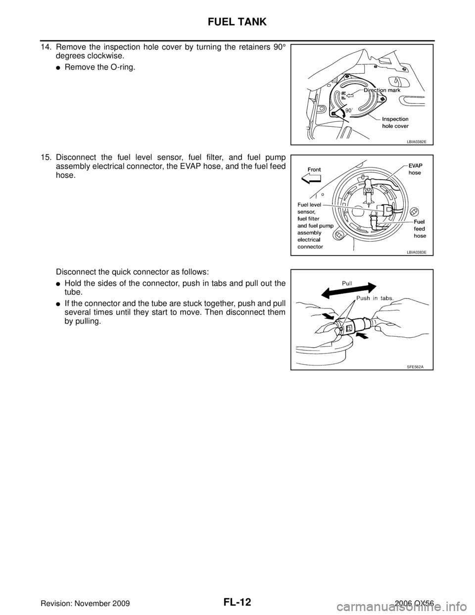
14. Remove the inspection hole cover by turning the retainers 90°
degrees clockwise.
�Remove the O-ring.
15. Disconnect the fuel level sensor, fuel filter, and fuel pump assembly electrical connector, the EVAP hose, and the fuel feed
hose.
Disconnect the quick connector as follows:
�Hold the sides of the connector, push in tabs and pull out the
tube.
�If the connector and the tube are stuck together, push and pull
several times until they start to move. Then disconnect them
by pulling.
LBIA0382E
LBIA0383E
SFE562A
Page 2069 of 3383

FL-14Revision: November 2009
FUEL TANK
2006 QX56
22. If necessary, remove the lock ring using Tool.
23. If necessary, remove the fuel level sensor, fuel filter, and fuelpump assembly. Discard the fuel level sensor, fuel filter, and fuel
pump assembly O-ring.
CAUTION:
�Do not bend the float arm during removal.
�Avoid impacts such as dropping when handling the com-
ponents.
INSTALLATION
Installation is in the reverse order of removal.
�For installation, use a new fuel level sensor, fuel filter, and fuel pump assembly O-ring.
�Connect the quick connector as follows:
–Check the connection for any damage or foreign materials.
–Align the connector with the pipe, then insert the connector straight into the pipe until a click is heard.
–After connecting the quick connector, make sure that the con-
nection is secure by checking as follows:
–Pull the tube and the connector to make sure they are securely
connected.
–Visually inspect the connector to make sure the two retainer tabs
are securely connected.
INSPECTION AFTER INSTALLATION
1. Turn the ignition switch ON but do not start engine, then check the fuel pipe and hose connections forleaks while applying fuel pressure.
2. Start the engine and rev it above idle, then check that there are no fuel leaks at any of the fuel pipe and hose connections.Tool number : — (J-46536)
LBIA0389E
PBIC1653E
Page 2078 of 3383

ON-VEHICLE SERVICEFSU-7
C
DF
G H
I
J
K L
M A
B
FSU
Revision: November 2009 2006 QX56
�Check with the manufacturer of your specific alignment machine for their recommended Service/Cali-
bration Schedule.
THE ALIGNMENT PROCESS
IMPORTANT: Use only the alignment specifications listed in this Service Manual. Refer to FSU-19, "Wheel
Alignment (Unladen*1 )*6" .
1. When displaying the alignment settings, many alignment machines use “indicators”: (Green/red, plus or minus, Go/No Go). Do NOT use these indicators.
�The alignment specifications programmed into your alignment machine that operate these indicators
may not be correct.
�This may result in an ERROR.
2. Some newer alignment machines are equipped with an optional “Rolling Compensation” method to “com- pensate” the sensors (alignment targets or head units). Do NOT use this “Rolling Compensation”
method.
�Use the “Jacking Compensation” method. After installing the alignment targets or head units, raise the
vehicle and rotate the wheels 1/2 turn both ways.
�See Instructions in the alignment machine you are using for more information.
CAMBER AND CASTER
1. Measure camber and caster of both the right and left wheels with a suitable alignment gauge and adjust as necessary to
specification.
NOTE:
Some vehicles may be equipped with straight (non-adjustable)
lover link bolts and washers. In order to adjust camber and
caster on these vehicles, first replace the lower link bolts and
washers with adjustable (cam) bolts and washers.
2. If outside of the specified value, adjust camber and caster using the cam bolts (1) in the front lower link (2).
CAUTION:
After adjusting the camber then check the toe-in.
NOTE:
Camber changes about 3' (0.05 °) with each graduation of one
cam bolt (1). Refer to table below for examples of lower link cam
bolt (1) effect on camber and caster.
3. Tighten the cam bolt nuts to specification. Refer to FSU-5, "
Components" .
TOE-IN
WARNING:
�Always perform the following procedure on a flat surface.
�Make sure that no person is in front of the vehicle before pushing it.Camber and
Caster
: Refer to
FSU-19, "
Wheel Alignment
(Unladen*1 )*6" .
SRA096A
WEIA0153E
Rear cam bolt 1 In 1 Out 1 In 1 Out 0 01 In 1 Out
Front cam bolt 1 Out 1 In 1 In 1 Out 1 In 1 Out 0 0
Camber
Degree minute
(Decimal degree) 0 (0) 0 (0) 7' (0.12
°) - 7' (-0.12°)3' (0.05°) - 3' (-0.05°)3' (0.05°)- 3' (-0.05°)
Caster
Degree minute
(Decimal degree) - 14' (-0.23
°) 14' (0.23°) 0 (0) 0 (0) 7' (0.12 °) - 7' (-0.12°) - 7' (-0.12°)7' (0.12°)
Page 2088 of 3383
 of each co")
KNUCKLEFSU-17
C
DF
G H
I
J
K L
M A
B
FSU
Revision: November 2009 2006 QX56
KNUCKLEPFP:40014
On-Vehicle Inspection and ServiceEES0025H
Make sure the mounting conditions (looseness, backlash) of each component and component status (wear,
damage) are within specifications. Refer to FSU-20, "
Ball Joint" .
Removal and InstallationEES0025I
REMOVAL
1. Remove wheel hub and bearing assembly. Refer to FAX-5, "Removal and Installation" .
�Disconnect wheel sensor harness connector. Do not remove wheel sensor from wheel hub and bearing
assembly for this procedure.
2. Remove steering outer socket from steering knuckle using Tool. CAUTION:
�Be careful not to damage ball joint boot.
�Temporarily tighten nut to prevent damage to threads and
to prevent Tool from coming off.
3. Remove the coil spring and shock absorber assembly using power tool. Refer to FSU-10, "
Removal and
Installation" .
4. Support lower link using a suitable jack.
5. Remove cotter pin and nut from upper link ball joint and discard the cotter pin.
1. Disc rotor 2. Wheel hub and bearing assembly 3. Wheel stud
4. Splash guard 5. Steering knuckle⇐Front
WDIA0328E
Tool number : HT72520000 (J-25730-A)
WGIA0130E
Page 2097 of 3383
. Using a fuel other than that specified could adversely affect
the emission control devices and systems, and")
GI-6
PRECAUTIONS
Revision: November 20092006 QX56
(i.e. Flexible Fuel Vehicle - FFV models). Using a fuel other than that specified could adversely affect
the emission control devices and systems, and could also affect the warranty coverage validity.
Precautions for Multiport Fuel Injection System or Engine Control SystemEAS001FA
�Before connecting or disconnecting any harness connector for
the multiport fuel injection system or ECM:
Turn ignition switch to “OFF” position.
Disconnect negative battery terminal.
Otherwise, there may be damage to ECM.
�Before disconnecting pressurized fuel line from fuel pump to
injectors, be sure to release fuel pressure.
�Be careful not to jar components such as ECM and mass air
flow sensor.
Precautions for HosesEAS001FB
HOSE REMOVAL AND INSTALLATION
�To prevent damage to rubber hose, do not pry off rubber hose
with tapered tool or screwdriver.
�To reinstall the rubber hose securely, make sure of hose inser-
tion length and clamp orientation. (If tube is equipped with hose
stopper, insert rubber hose into tube until it butts up against
hose stopper.)
HOSE CLAMPING
�If old rubber hose is re-used, install hose clamp in its original
position (at the indentation where the old clamp was). If there is
a trace of tube bulging left on the old rubber hose, align rubber
hose at that position.
�Discard old clamps; replace with new ones.
SGI787
SMA019D
SMA020D
SMA021D
Page 2101 of 3383

GI-10
HOW TO USE THIS MANUAL
Revision: November 20092006 QX56
SYMBOLS
How to Follow Trouble DiagnosesEAS001FJ
NOTICE:
Trouble diagnoses indicates work procedures required to diagnose problems effectively. Observe the following
instructions before diagnosing.
1.Before performing trouble diagnoses, read the “Preliminary Check”, the “Symptom Chart” or the
“Work Flow”.
2. After repairs, re-check that the problem has been completely eliminated.
1. Union bolt 2. Copper washer 3. Brake hose
4. Cap 5. Bleed valve 6. Sliding pin bolt
7. Piston seal 8. Piston 9. Piston boot
10. Cylinder body 11. Sliding pin 12. Torque member mounting bolt
13. Washer 14. Sliding pin boot 15. Bushing
16. Torque member 17. Inner shim cover 18. Inner shim
19. Inner pad 20. Pad retainer 21. Pad wear sensor
22. Outer pad 23. Outer shim 24. Outer shim cover
1: PBC (Poly Butyl Cuprysil) grease
or silicone-based grease 2: Rubber grease
: Brake fluid
Refer to GI section for additional symbol definitions.
SFIA2959E
SAIA0749E
Page 2120 of 3383

SERVICE INFORMATION FOR ELECTRICAL INCIDENTGI-29
C
DE
F
G H
I
J
K L
M B
GI
Revision: November 2009 2006 QX56
�Freezing
�Water intrusion
�Electrical load
�Cold or hot start up
Get a thorough description of the incident from the customer. It is important for simulating the conditions of the
problem.
Vehicle Vibration
The problem may occur or become worse while driving on a rough road or when engine is vibrating (idle with
A/C on). In such a case, you will want to check for a vibration related condition. Refer to the following illustra-
tion.
CONNECTORS & HARNESS
Determine which connectors and wiring harness would affect the electrical system you are inspecting. Gently
shake each connector and harness while monitoring the system for the incident you are trying to duplicate.
This test may indicate a loose or poor electrical connection.
HINT
Connectors can be exposed to moisture. It is possible to get a thin film of corrosion on the connector termi-
nals. A visual inspection may not reveal this without disconnecting the connector. If the problem occurs inter-
mittently, perhaps the problem is caused by corrosion. It is a good idea to disconnect, inspect and clean the
terminals on related connectors in the system.
SENSORS & RELAYS
Gently apply a slight vibration to sensors and relays in the system you are inspecting.
This test may indicate a loose or poorly mounted sensor or relay.
ENGINE COMPARTMENT
There are several reasons a vehicle or engine vibration could cause an electrical complaint. Some of the
things to check for are:
�Connectors not fully seated.
�Wiring harness not long enough and is being stressed due to engine vibrations or rocking.
�Wires laying across brackets or moving components.
�Loose, dirty or corroded ground wires.
�Wires routed too close to hot components.
To inspect components under the hood, start by verifying the integrity of ground connections. (Refer to Ground
Inspection described later.) First check that the system is properly grounded. Then check for loose connection
by gently shaking the wiring or components as previously explained. Using the wiring diagrams inspect the
wiring for continuity.
BEHIND THE INSTRUMENT PANEL
An improperly routed or improperly clamped harness can become pinched during accessory installation. Vehi-
cle vibration can aggravate a harness which is routed along a bracket or near a screw.
SGI839