Page 2128 of 3383
SERVICE INFORMATION FOR ELECTRICAL INCIDENTGI-37
C
DE
F
G H
I
J
K L
M B
GI
Revision: November 2009 2006 QX56
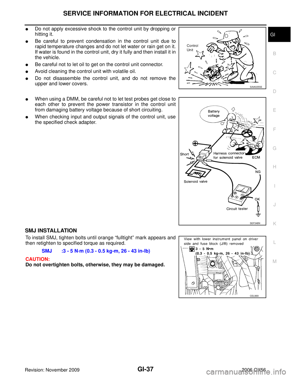
�Do not apply excessive shock to the control unit by dropping or
hitting it.
�Be careful to prevent condensation in the control unit due to
rapid temperature changes and do not let water or rain get on it.
If water is found in the control unit, dry it fully and then install it in
the vehicle.
�Be careful not to let oil to get on the control unit connector.
�Avoid cleaning the control unit with volatile oil.
�Do not disassemble the control unit, and do not remove the
upper and lower covers.
�When using a DMM, be careful not to let test probes get close to
each other to prevent the power transistor in the control unit
from damaging battery voltage because of short circuiting.
�When checking input and output signals of the control unit, use
the specified check adapter.
SMJ INSTALLATION
To install SMJ, tighten bolts until orange “fulltight” mark appears and
then retighten to specified torque as required.
CAUTION:
Do not overtighten bolts, otherwise, they may be damaged.
SAIA0255E
SEF348N
SMJ :3 - 5 N·m (0.3 - 0.5 kg-m, 26 - 43 in-lb)
CEL969
Page 2130 of 3383
![INFINITI QX56 2006 Factory Service Manual CONSULT-II CHECKING SYSTEMGI-39
C
DE
F
G H
I
J
K L
M B
GI
Revision: November 2009 2006 QX56
x: Applicable.
*1: IVIS (NATS) [Infiniti Vehicle Immobilizer System (Nissan Anti-Theft System)].
*2: This sy INFINITI QX56 2006 Factory Service Manual CONSULT-II CHECKING SYSTEMGI-39
C
DE
F
G H
I
J
K L
M B
GI
Revision: November 2009 2006 QX56
x: Applicable.
*1: IVIS (NATS) [Infiniti Vehicle Immobilizer System (Nissan Anti-Theft System)].
*2: This sy](/manual-img/42/57028/w960_57028-2129.png)
CONSULT-II CHECKING SYSTEMGI-39
C
DE
F
G H
I
J
K L
M B
GI
Revision: November 2009 2006 QX56
x: Applicable.
*1: IVIS (NATS) [Infiniti Vehicle Immobilizer System (Nissan Anti-Theft System)].
*2: This system is shown with IVIS (NATS) using program card AEN04A-1 or later.
Nickel Metal Hydride Battery Replacement EAS001FR
CONSULT-II contains a nickel metal hydride battery. When replacing the battery obey the following:
WARNING:
Replace the nickel metal hydride battery with Genuine CONSULT-II battery only. Use of another bat-
tery may present a risk of fire or explosion. The battery may present a fire or chemical burn hazard if
mistreated. Do not recharge, disassemble or dispose of in fire.
Keep the battery out of reach of children and discard used battery conforming to the local regulations.
Checking EquipmentEAS001TP
When ordering the below equipment, contact your NISSAN distributor.
CAUTION:
�Previous CONSULT-II “I” and “Y” DLC-I and DLC-II cables should NOT be used anymore because
their DDL connector pins can be damaged during cable swapping.
�If CONSULT-II is used with no connection of CONSULT-II CONVERTER, malfunctions might be
detected in self- diagnosis depending on control unit which carries out CAN communication.
�If CONSULT-II CONVERTER is not connected with CONSULT-II, the vehicle enters “FAIL SAFE
MODE” which will “LIGHT UP the HEAD LIGHT” and /or “COOLING FAN ROTATING” when CON-
SULT-II is started.
NOTE:
�The CONSULT-II must be used in conjunction with a program card.
CONSULT-II does not require loading (Initialization) procedure.
�Be sure the CONSULT-II is turned OFF before installing or removing a program card.
CONSULT-II Start ProcedureEAS001TQ
NOTE:
Turning ignition switch off when performing CAN diagnosis could cause CAN memory to be erased.
1. Connect CONSULT-II and CONSULT-II CONVERTER to the data link connector.
Tool name Description
NISSAN CONSULT-II (J-44200)
1. CONSULT-II unit (Tester internal soft: Resident Version 3.4.0) and accessories.
2. Program card UED05C-1 and AEN04A-1 (for NATS) or later, to confirm the best combination
of these software, refer to CONSULT-II Opera-
tion Manual.
3. CONSULT-II CONVERTER.
4. "CONSULT-II pigtail" cable.
SAIA0363E
PAIA0070E
Page 2175 of 3383
GW-30
POWER WINDOW SYSTEM
Revision: November 20092006 QX56
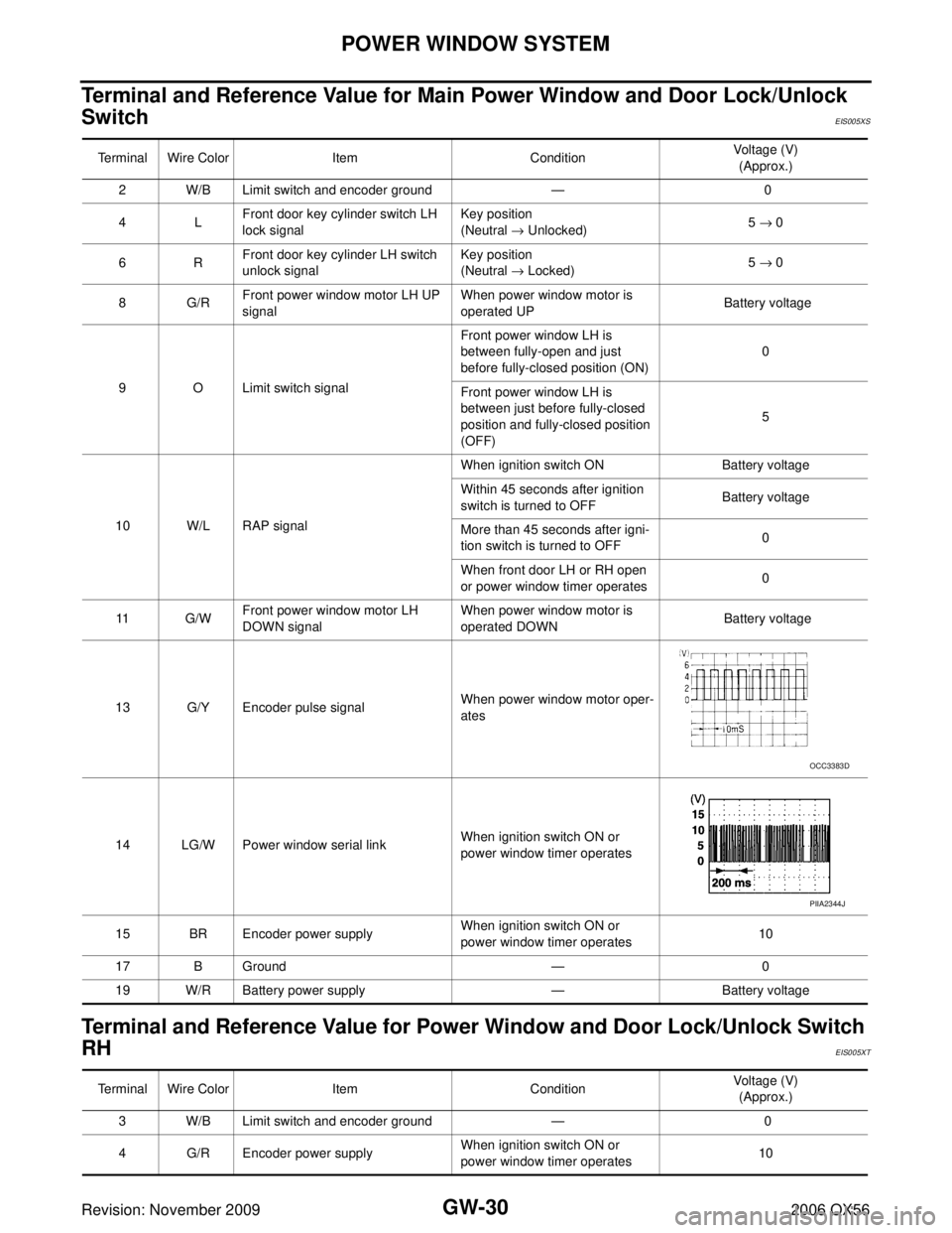
Terminal and Reference Value for Main Power Window and Door Lock/Unlock
Switch
EIS005XS
Terminal and Reference Value for Power Window and Door Lock/Unlock Switch
RH
EIS005XT
Terminal Wire ColorItemCondition Voltage (V)
(Approx.)
2 W/B Limit switch and encoder ground — 0
4L Front door key cylinder switch LH
lock signal Key position
(Neutral
→ Unlocked) 5
→ 0
6R Front door key cylinder LH switch
unlock signal Key position
(Neutral
→ Locked) 5
→ 0
8G/R Front power window motor LH UP
signal When power window motor is
operated UP
Battery voltage
9 O Limit switch signal Front power window LH is
between fully-open and just
before fully-closed position (ON)
0
Front power window LH is
between just before fully-closed
position and fully-closed position
(OFF) 5
10 W/L RAP signal When ignition switch ON
Battery voltage
Within 45 seconds after ignition
switch is turned to OFF Battery voltage
More than 45 seconds after igni-
tion switch is turned to OFF 0
When front door LH or RH open
or power window timer operates 0
11 G/W Front power window motor LH
DOWN signal When power window motor is
operated DOWN
Battery voltage
13 G/Y Encoder pulse signal When power window motor oper-
ates
14 LG/W Power window serial link When ignition switch ON or
power window timer operates
15 BR Encoder power supply When ignition switch ON or
power window timer operates10
17 B Ground —0
19 W/R Battery power supply —Battery voltage
OCC3383D
PIIA2344J
Terminal Wire Color ItemCondition Voltage (V)
(Approx.)
3 W/B Limit switch and encoder ground — 0
4 G/R Encoder power supply When ignition switch ON or
power window timer operates10
Page 2176 of 3383
POWER WINDOW SYSTEMGW-31
C
DE
F
G H
J
K L
M A
B
GW
Revision: November 2009 2006 QX56
8LFront power window motor RH UP
signal When power window motor is
operated UP
Battery voltage
9G Front power window motor RH
DOWN signal When power window motor is
operated DOWN
Battery voltage
10 W/R Battery power supply —Battery voltage
11 B Ground —0
12 G/Y Encoder pulse signal When power window motor oper-
ates
15 G/W Limit switch signal Rear power window RH is
between fully-open and just
before fully-closed position (ON)
0
Rear power window RH is
between just before fully-closed
position and fully-closed position
(OFF) 5
16 LG/W Power window serial link When ignition switch is ON or
power window timer operating
Terminal Wire Color
ItemCondition Voltage (V)
(Approx.)
OCC3383D
PIIA2344J
Page 2177 of 3383
GW-32
POWER WINDOW SYSTEM
Revision: November 20092006 QX56
Terminal and Reference Value for BCMEIS005XU
Terminal Wire ColorItemCondition Voltage (V)
(Approx.)
11 O Ignition switch (ACC or ON) Ignition switch
(ACC or ON position) Battery voltage
12 R/L Front door switch RH signal ON (Open)
Battery voltage
OFF (Close) 0
22 W/V BUS When ignition switch ON or
power window timer operates
38 W/L Ignition switch (ON or START) Ignition switch
(ON or START position)
Battery voltage
47 SB Front door switch LH signal ON (Open)
Battery voltage
OFF (Close) 0
67 B Ground —0
68 W/L Power window power supply
(RAP) When ignition switch ON
Battery voltage
Within 45 seconds after ignition
switch is turned to OFF Battery voltage
More than 45 seconds after igni-
tion switch is turned to OFF 0
When front door LH or RH is
open or power window timer
operates 0
69 W/R Power window power supply
(BAT) —
Battery voltage
70 W/B Battery power supply —Battery voltage
PIIA2344J
Page 2182 of 3383
POWER WINDOW SYSTEMGW-37
C
DE
F
G H
J
K L
M A
B
GW
Revision: November 2009 2006 QX56
BCM Power Supply and Ground Circuit CheckEIS005XY
1. CHECK FUSE AND FUSIBLE LINK
�Check 10A fuse (No. 4, located in the fuse block (J/B)]
�Check 10A fuse (No. 59, located in the fuse and relay box)
�Check 50A fusible link (letter f , located in the fuse and fusible link box)
NOTE:
Refer to GW-15, "
Component Parts and Harness Connector Location" .
OK or NG
OK >> GO TO 2.
NG >> If fuse is blown, be sure to eliminate cause of malfunction before installing new fuse. Refer to PG-
3, "PRECAUTIONS" .
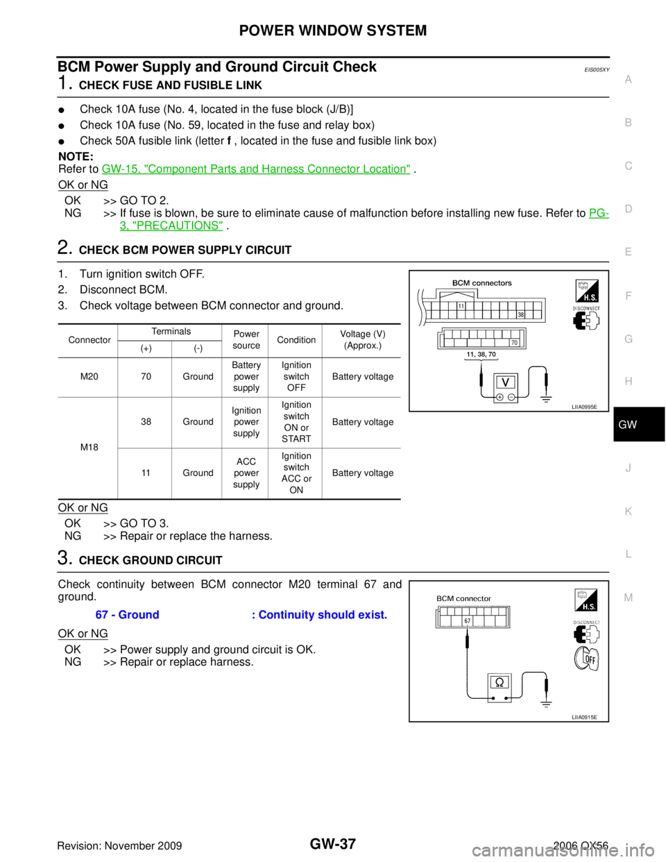
2. CHECK BCM POWER SUPPLY CIRCUIT
1. Turn ignition switch OFF.
2. Disconnect BCM.
3. Check voltage between BCM connector and ground.
OK or NG
OK >> GO TO 3.
NG >> Repair or replace the harness.
3. CHECK GROUND CIRCUIT
Check continuity between BCM connector M20 terminal 67 and
ground.
OK or NG
OK >> Power supply and ground circuit is OK.
NG >> Repair or replace harness.
Connector Terminals
Power
source Condition Voltage (V)
(Approx.)
(+) (-)
M20 70 Ground Battery
power
supply Ignition
switch
OFF Battery voltage
M18 38 Ground
Ignition
power
supply Ignition
switch
ON or
START Battery voltage
11 Ground ACC
power
supply Ignition
switch
ACC or ON Battery voltage
LIIA0995E
67 - Ground
: Continuity should exist.
LIIA0915E
Page 2183 of 3383
GW-38
POWER WINDOW SYSTEM
Revision: November 20092006 QX56
Main Power Window and Door Lock/Unlock Switch Power Supply and Ground
Circuit Check
EIS005XZ
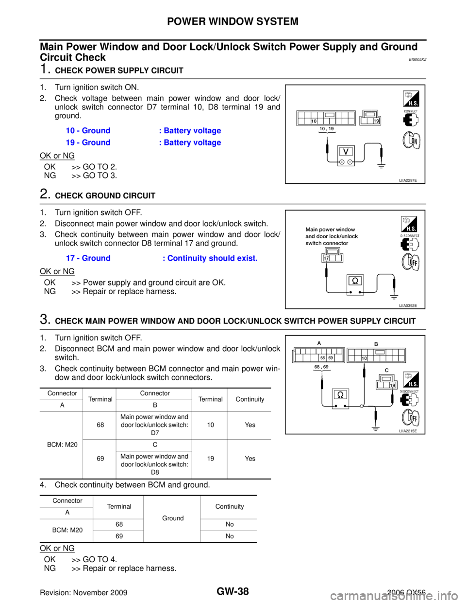
1. CHECK POWER SUPPLY CIRCUIT
1. Turn ignition switch ON.
2. Check voltage between main power window and door lock/ unlock switch connector D7 terminal 10, D8 terminal 19 and
ground.
OK or NG
OK >> GO TO 2.
NG >> GO TO 3.
2. CHECK GROUND CIRCUIT
1. Turn ignition switch OFF.
2. Disconnect main power window and door lock/unlock switch.
3. Check continuity between main power window and door lock/ unlock switch connector D8 terminal 17 and ground.
OK or NG
OK >> Power supply and ground circuit are OK.
NG >> Repair or replace harness.
3. CHECK MAIN POWER WINDOW AND DOOR LOCK/UNLOCK SWITCH POWER SUPPLY CIRCUIT
1. Turn ignition switch OFF.
2. Disconnect BCM and main power window and door lock/unlock switch.
3. Check continuity between BCM connector and main power win- dow and door lock/unlock switch connectors.
4. Check continuity between BCM and ground.
OK or NG
OK >> GO TO 4.
NG >> Repair or replace harness. 10 - Ground
: Battery voltage
19 - Ground : Battery voltage
LIIA2297E
17 - Ground : Continuity should exist.
LIIA0392E
Connector
Terminal Connector
Terminal Continuity
AB
BCM: M20 68
Main power window and
door lock/unlock switch:
D7 10 Yes
69 C
19 Yes
Main power window and
door lock/unlock switch: D8
Connector Terminal
GroundContinuity
A
BCM: M20 68
No
69 No
LIIA2215E
Page 2184 of 3383
POWER WINDOW SYSTEMGW-39
C
DE
F
G H
J
K L
M A
B
GW
Revision: November 2009 2006 QX56
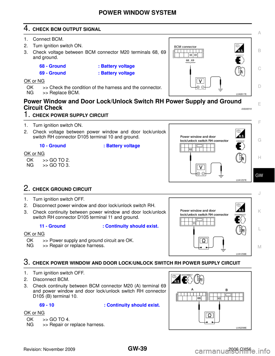
4. CHECK BCM OUTPUT SIGNAL
1. Connect BCM.
2. Turn ignition switch ON.
3. Check voltage between BCM connector M20 terminals 68, 69 and ground.
OK or NG
OK >> Check the condition of the harness and the connector.
NG >> Replace BCM.
Power Window and Door Lock/Unlock Switch RH Power Supply and Ground
Circuit Check
EIS005Y0
1. CHECK POWER SUPPLY CIRCUIT
1. Turn ignition switch ON.
2. Check voltage between power window and door lock/unlock switch RH connector D105 terminal 10 and ground.
OK or NG
OK >> GO TO 2.
NG >> GO TO 3.
2. CHECK GROUND CIRCUIT
1. Turn ignition switch OFF.
2. Disconnect power window and door lock/unlock switch RH.
3. Check continuity between power window and door lock/unlock switch RH connector D105 terminal 11 and ground.
OK or NG
OK >> Power supply and ground circuit are OK.
NG >> Repair or replace harness.
3. CHECK POWER WINDOW AND DOOR LOCK/UNLOCK SWITCH RH POWER SUPPLY CIRCUIT
1. Turn ignition switch OFF.
2. Disconnect BCM.
3. Check continuity between BCM connector M20 (A) terminal 69 and power window and door lock/unlock switch RH connector
D105 (B) terminal 10.
OK or NG
OK >> GO TO 4.
NG >> Repair or replace harness. 68 - Ground
: Battery voltage
69 - Ground : Battery voltage
LIIA0917E
10 - Ground : Battery voltage
LIIA1257E
11 - Ground: Continuity should exist.
LIIA1258E
69 - 10 : Continuity should exist.
LIIA2298E