Page 2208 of 3383

POWER WINDOW SYSTEMGW-63
C
DE
F
G H
J
K L
M A
B
GW
Revision: November 2009 2006 QX56
4. CHECK REAR POWER VENT WINDOW RELAY (OPEN) CIRCUIT
1. Disconnect rear power vent window switch.
2. Check continuity between rear power vent window relay (OPEN) connector M87 terminal 2 and rear power vent window switch
connector R103 terminal 3.
OK or NG
OK >> Replace rear power vent window switch.
NG >> Repair or replace harness.
Rear Power Vent Window Relay (CLOSE) CheckEIS005YL
1. CHECK REAR POWER VENT WINDOW RELAY (CLOSE) POWER SUPPLY CIRCUIT
1. Turn ignition switch OFF.
2. Disconnect rear power vent window relay (CLOSE).
3. Turn ignition switch ON.
4. Check voltage between rear power vent window relay (CLOSE) connector and ground.
OK or NG
OK >> GO TO 2.
NG >> Repair or replace harness.
2. CHECK REAR POWER VENT WINDOW RELAY (CLOSE)
Check continuity between rear power vent window relay (CLOSE)
terminals 3 and 4, 3 and 5.
OK or NG
OK >> GO TO 3.
NG >> Replace rear power vent window relay (CLOSE). 2 - 3
: Continuity should exist.
LIIA1568E
ConnectorTerminals
Voltage (V)
(Approx.)
(+) (-)
M89 1
Ground Battery voltage
5
LIIA1565E
Terminal Condition Continuity
34 12V direct current supply
between terminals 1 and 2
No
No current supply Yes
35 12V direct current supply
between terminals 1 and 2
Ye s
No current supply No
WIIA0291E
Page 2225 of 3383

GW-80
REAR WINDOW DEFOGGER
Revision: November 20092006 QX56
Terminal and Reference Value for BCMEIS005YR
Terminal and Reference Value for IPDM E/REIS005YS
Work FlowEIS005YT
1. Check the symptom and customer's requests.
2. Understand the outline of system. Refer to GW-75, "
System Description" .
3. According to the trouble diagnosis chart, repair or replace the cause of the malfunction. Refer to GW-82,
"Trouble Diagnoses Symptom Chart" .
4. Does rear window defogger and door mirror defogger operate normally? YES: GO TO 5, NO: GO TO 3.
5. Inspection end.
Terminal Wire color ItemConditionVoltage (V)
(Approx.)
9Y /B Rear window defogger
switch signal When rear window defogger switch is pressed.
0
When rear window defogger switch is OFF. 5
38 W/L Ignition switch ON or START Ignition switch (ON or START position) Battery voltage
39 L CAN-H ——
40 P CAN-L ——
67 B Ground —0
70 W/B Battery power supply —Battery voltage
Terminal Wire color ItemConditionVoltage (V)
(Approx.)
38 B Ground (Power) —0
39 L CAN-H ——
40 P CAN-L ——
59 B Ground (Signal) —0
60 BRear window defogger output
signal When rear window defogger switch is ON. Battery voltage
When rear window defogger switch is OFF.
0
Page 2229 of 3383
![INFINITI QX56 2006 Factory Service Manual GW-84
REAR WINDOW DEFOGGER
Revision: November 20092006 QX56
BCM Power Supply and Ground Circuit CheckEIS005YW
1. CHECK FUSES AND FUSIBLE LINK
�Check 10A fuse (No. 8, located in the fuse block (J/B)]
� INFINITI QX56 2006 Factory Service Manual GW-84
REAR WINDOW DEFOGGER
Revision: November 20092006 QX56
BCM Power Supply and Ground Circuit CheckEIS005YW
1. CHECK FUSES AND FUSIBLE LINK
�Check 10A fuse (No. 8, located in the fuse block (J/B)]
�](/manual-img/42/57028/w960_57028-2228.png)
GW-84
REAR WINDOW DEFOGGER
Revision: November 20092006 QX56
BCM Power Supply and Ground Circuit CheckEIS005YW
1. CHECK FUSES AND FUSIBLE LINK
�Check 10A fuse (No. 8, located in the fuse block (J/B)]
�Check 10A fuse (No. 59, located in the fuse and relay box)
�Check 50A fusible link (letter f , located in the fuse and fusible link box)
NOTE:
Refer to GW-74, "
Component Parts and Harness Connector Location" .
OK or NG
OK >> GO TO 2.
NG >> If fuse is blown, be sure to eliminate cause of malfunction before installing new fuse. Refer to PG-
4, "POWER SUPPLY ROUTING CIRCUIT" .
2. CHECK POWER SUPPLY CIRCUIT
1. Turn ignition switch ON.
2. Check voltage between BCM connector M18, M20 terminals 38, 70
and ground.
OK or NG
OK >> GO TO 3.
NG >> Repair or replace harness.
3. CHECK GROUND CIRCUIT
1. Turn ignition switch OFF.
2. Disconnect BCM.
3. Check continuity between BCM connector M20 terminal 67 and ground.
OK or NG
OK >> BCM power supply and ground circuit is OK.
NG >> Repair or replace harness. 70 - Ground
: Battery voltage
38 - Ground : Battery voltage
LIIA0914E
67 - Ground : Continuity should exist.
LIIA0915E
Page 2231 of 3383

GW-86
REAR WINDOW DEFOGGER
Revision: November 20092006 QX56
3. CHECK BCM OUTPUT SIGNAL
1. Connect BCM.
2. Turn ignition switch ON.
3. Check voltage between BCM connector M18 terminal 9 and ground.
OK or NG
OK >> Replace front air control. Refer to ATC-144, "FRONT
AIR CONTROL" .
NG >> Replace BCM. Refer to BCS-20, "
BCM" .
Rear Window Defogger Circuit CheckEIS0062Z
1. CHECK FUSES
Check if any of the following fuses in IPDM E/R are blown.
NOTE:
Refer to GW-74, "
Component Parts and Harness Connector Location" .
OK or NG
OK >> GO TO 2.
NG >> If fuse is blown, be sure to eliminate cause of malfunction before installing new fuse, refer to GW-
74, "Component Parts and Harness Connector Location" .
2. CHECK REAR WINDOW DEFOGGER POWER SUPPLY CIRCUIT
1. Turn ignition switch OFF.
2. Disconnect rear window defogger.
3. Turn ignition switch ON.
4. Check voltage between rear window defogger connector D406 terminal + and ground.
OK or NG
OK >> GO TO 3.
NG >> GO TO 4. 9 - Ground
: Approx. 5
WIIA0523E
COMPONENT PARTS AMPEREFUSE NO.
IPDM E/R 15A46
IPDM E/R 15A47
ConnectorTerminals
ConditionVoltage (V)
(Approx.)
(+) (-)
D406 + Ground Rear window defogger
switch ON.
Battery voltage
Rear window defogger
switch OFF. 0
LIIA0655E
Page 2232 of 3383

REAR WINDOW DEFOGGERGW-87
C
DE
F
G H
J
K L
M A
B
GW
Revision: November 2009 2006 QX56
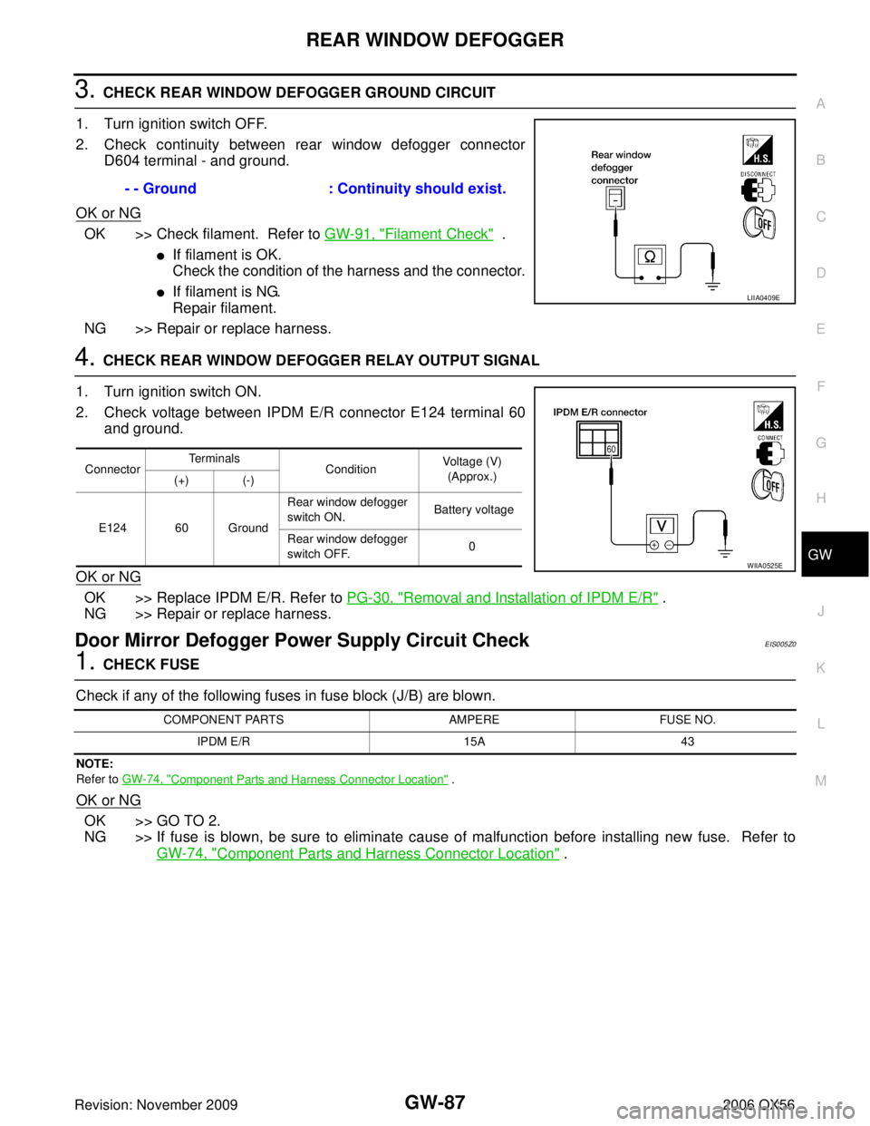
3. CHECK REAR WINDOW DEFOGGER GROUND CIRCUIT
1. Turn ignition switch OFF.
2. Check continuity between rear window defogger connector D604 terminal - and ground.
OK or NG
OK >> Check filament. Refer to GW-91, "Filament Check" .
�If filament is OK.
Check the condition of the harness and the connector.
�If filament is NG.
Repair filament.
NG >> Repair or replace harness.
4. CHECK REAR WINDOW DEFOGGER RELAY OUTPUT SIGNAL
1. Turn ignition switch ON.
2. Check voltage between IPDM E/R connector E124 terminal 60 and ground.
OK or NG
OK >> Replace IPDM E/R. Refer to PG-30, "Removal and Installation of IPDM E/R" .
NG >> Repair or replace harness.
Door Mirror Defogger Power Supply Circuit CheckEIS005Z0
1. CHECK FUSE
Check if any of the following fuses in fuse block (J/B) are blown.
NOTE:
Refer to GW-74, "
Component Parts and Harness Connector Location" .
OK or NG
OK >> GO TO 2.
NG >> If fuse is blown, be sure to eliminate cause of malfunction before installing new fuse. Refer to
GW-74, "
Component Parts and Harness Connector Location" .
- - Ground
: Continuity should exist.
LIIA0409E
ConnectorTerminals
ConditionVoltage (V)
(Approx.)
(+) (-)
E124 60 Ground Rear window defogger
switch ON.
Battery voltage
Rear window defogger
switch OFF. 0
WIIA0525E
COMPONENT PARTS
AMPEREFUSE NO.
IPDM E/R 15A43
Page 2233 of 3383

GW-88
REAR WINDOW DEFOGGER
Revision: November 20092006 QX56
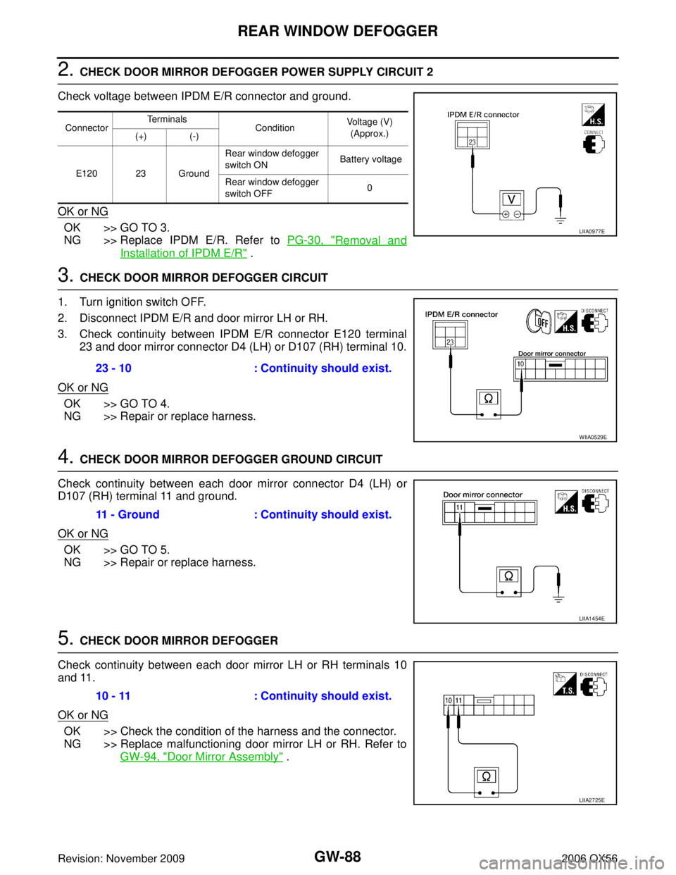
2. CHECK DOOR MIRROR DEFOGGER POWER SUPPLY CIRCUIT 2
Check voltage between IPDM E/R connector and ground.
OK or NG
OK >> GO TO 3.
NG >> Replace IPDM E/R. Refer to PG-30, "
Removal and
Installation of IPDM E/R" .
3. CHECK DOOR MIRROR DEFOGGER CIRCUIT
1. Turn ignition switch OFF.
2. Disconnect IPDM E/R and door mirror LH or RH.
3. Check continuity between IPDM E/R connector E120 terminal 23 and door mirror connector D4 (LH) or D107 (RH) terminal 10.
OK or NG
OK >> GO TO 4.
NG >> Repair or replace harness.
4. CHECK DOOR MIRROR DEFOGGER GROUND CIRCUIT
Check continuity between each door mirror connector D4 (LH) or
D107 (RH) terminal 11 and ground.
OK or NG
OK >> GO TO 5.
NG >> Repair or replace harness.
5. CHECK DOOR MIRROR DEFOGGER
Check continuity between each door mirror LH or RH terminals 10
and 11.
OK or NG
OK >> Check the condition of the harness and the connector.
NG >> Replace malfunctioning door mirror LH or RH. Refer to GW-94, "
Door Mirror Assembly" .
Connector Terminals
ConditionVoltage (V)
(Approx.)
(+) (-)
E120 23 Ground Rear window defogger
switch ON
Battery voltage
Rear window defogger
switch OFF 0
LIIA0977E
23 - 10
: Continuity should exist.
WIIA0529E
11 - Ground: Continuity should exist.
LIIA1454E
10 - 11 : Continuity should exist.
LIIA2725E
Page 2234 of 3383

REAR WINDOW DEFOGGERGW-89
C
DE
F
G H
J
K L
M A
B
GW
Revision: November 2009 2006 QX56
Door Mirror LH (Door Mirror Defogger) Circuit CheckEIS005Z1
1. CHECK DOOR MIRROR DEFOGGER POWER SUPPLY CIRCUIT
1. Turn ignition switch OFF.
2. Disconnect door mirror LH.
3. Turn ignition switch ON.
4. Check voltage between door mirror LH connector and ground.
OK or NG
OK >> GO TO 2.
NG >> Repair or replace harness.
2. CHECK DOOR MIRROR DEFOGGER GROUND CIRCUIT
1. Turn ignition switch OFF.
2. Check continuity between door mirror LH connector D4 terminal 11 and ground.
OK or NG
OK >> GO TO 3.
NG >> Repair or replace harness.
3. CHECK DOOR MIRROR DEFOGGER
Check continuity between door mirror LH terminals 10 and 11.
OK or NG
OK >> Repair or replace harness.
NG >> Replace door mirror LH. Refer to GW-94, "
Door Mirror
Assembly" .
ConnectorTe r m i n a l s
ConditionVoltage (V)
(Approx.)
(+) (-)
D4 10 Ground Rear window defogger
switch ON
Battery voltage
Rear window defogger
switch OFF 0
LIIA1456E
11 - Ground
: Continuity should exist.
LIIA1458E
10 - 11 : Continuity should exist.
LIIA2725E
Page 2235 of 3383

GW-90
REAR WINDOW DEFOGGER
Revision: November 20092006 QX56
Door Mirror RH (Door Mirror Defogger) Circuit CheckEIS005Z2
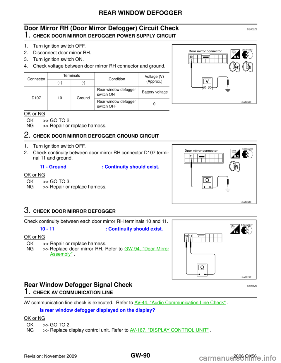
1. CHECK DOOR MIRROR DEFOGGER POWER SUPPLY CIRCUIT
1. Turn ignition switch OFF.
2. Disconnect door mirror RH.
3. Turn ignition switch ON.
4. Check voltage between door mirror RH connector and ground.
OK or NG
OK >> GO TO 2.
NG >> Repair or replace harness.
2. CHECK DOOR MIRROR DEFOGGER GROUND CIRCUIT
1. Turn ignition switch OFF.
2. Check continuity between door mirror RH connector D107 termi- nal 11 and ground.
OK or NG
OK >> GO TO 3.
NG >> Repair or replace harness.
3. CHECK DOOR MIRROR DEFOGGER
Check continuity between each door mirror RH terminals 10 and 11.
OK or NG
OK >> Repair or replace harness.
NG >> Replace door mirror RH. Refer to GW-94, "
Door Mirror
Assembly" .
Rear Window Defogger Signal CheckEIS005Z3
1. CHECK AV COMMUNICATION LINE
AV communication line check is executed. Refer to AV- 4 4 , "
Audio Communication Line Check" .
OK or NG
OK >> GO TO 2.
NG >> Replace display control unit. Refer to AV- 1 6 7 , "
DISPLAY CONTROL UNIT" .
ConnectorTerminals
ConditionVoltage (V)
(Approx.)
(+) (-)
D107 10 Ground Rear window defogger
switch ON
Battery voltage
Rear window defogger
switch OFF 0
LIIA1456E
11 - Ground
: Continuity should exist.
LIIA1458E
10 - 11 : Continuity should exist.
LIIA2725E
Is rear window defogger displayed on the display?