Page 1875 of 3383

EI-26
REAR SPOILER
Revision: November 20092006 QX56
REAR SPOILERPFP:96030
Removal and InstallationEIS004WM
REMOVAL
1. Disconnect the negative and positive battery cables, then wait at least 3 minutes.
2. Remove back door trim. Refer to EI-42, "
BACK DOOR TRIM" .
3. Disconnect harness to high-mount stop lamp.
4. Disconnect washer tube.
5. Remove nuts, release clips and remove rear spoiler.
�Release adhesive tape with sawing motion from monofilament line that has knots in it.
�Remove residue of adhesive tape completely from vehicle surface with strip-off wheel or equivalent.
CAUTION:
�Never apply tack-paper adhesive remover to body panel surface finished with lacquer-based
paints.
�Use care not to damage the vehicle surface during adhesive tape residue removal.
6. Remove nuts and remove high-mount stop lamp.
INSTALLATION
Installation is in the reverse order of removal.
NOTE:
Apply adhesion promoter only to areas of rear spoiler that tape will be applied, as required.
1. Grommet 2. Clip C101 3. Nut
4. Rear air spoiler 5. High-mount stop lamp
WIIA0961E
Page 1877 of 3383
EI-28
DOOR OUTSIDE MOLDING
Revision: November 20092006 QX56
DOOR OUTSIDE MOLDINGPFP:82820
Removal and InstallationEIS007XI
Front Door
Removal
1. Open the front door and door window fully.
2. Remove the battery negative terminal.
3. Remove the door mirror. Refer to GW-94, "
Door Mirror Assembly" .
4. Remove the front door outside molding.
�Remove the hole cover and remove screw.
�Lift the molding from rear edge first.
�Disconnect the clips from the flange working forward.
Installation
Installation is in the reverse order of removal.
WIIA0842E
Page 1881 of 3383
EI-32
DOOR FINISHER
Revision: November 20092006 QX56
DOOR FINISHERPFP:80900
Removal and InstallationEIS004WQ
Front Door
REMOVAL
1. Disconnect the negative battery cable.
2. Remove power window switch assembly.
�Disconnect harness connectors.
3. Remove pull handle cover.
�Remove screws behind pull handle cover.
4. Remove cap from pull handle escutcheon and remove screw.
5. Remove pull handle escutcheon.
�Remove screws behind pull handle escutcheon.
6. Remove armrest.
WIIA0965E
1. Power window switch assembly 2. Armrest 3. Front door finisher LH
4. Pull handle cover 5. Pull handle escutcheon 6. Cap
7. Door lock knob 8. Step lamp 9. Seat memory switch
Page 1882 of 3383
DOOR FINISHEREI-33
C
DE
F
G H
J
K L
M A
B
EI
Revision: November 2009 2006 QX56
�Remove screw behind armrest.
7. Remove memory seat switch.
�Disconnect harness connector.
8. Remove step lamp.
�Disconnect harness connector.
9. Remove door finisher and disconnect lock cable and handle cable from door handle assembly. Refer to BL-131, "
FRONT DOOR LOCK" .
10. Remove door lock knob.
INSTALLATION
Installation is in the reverse order of removal.
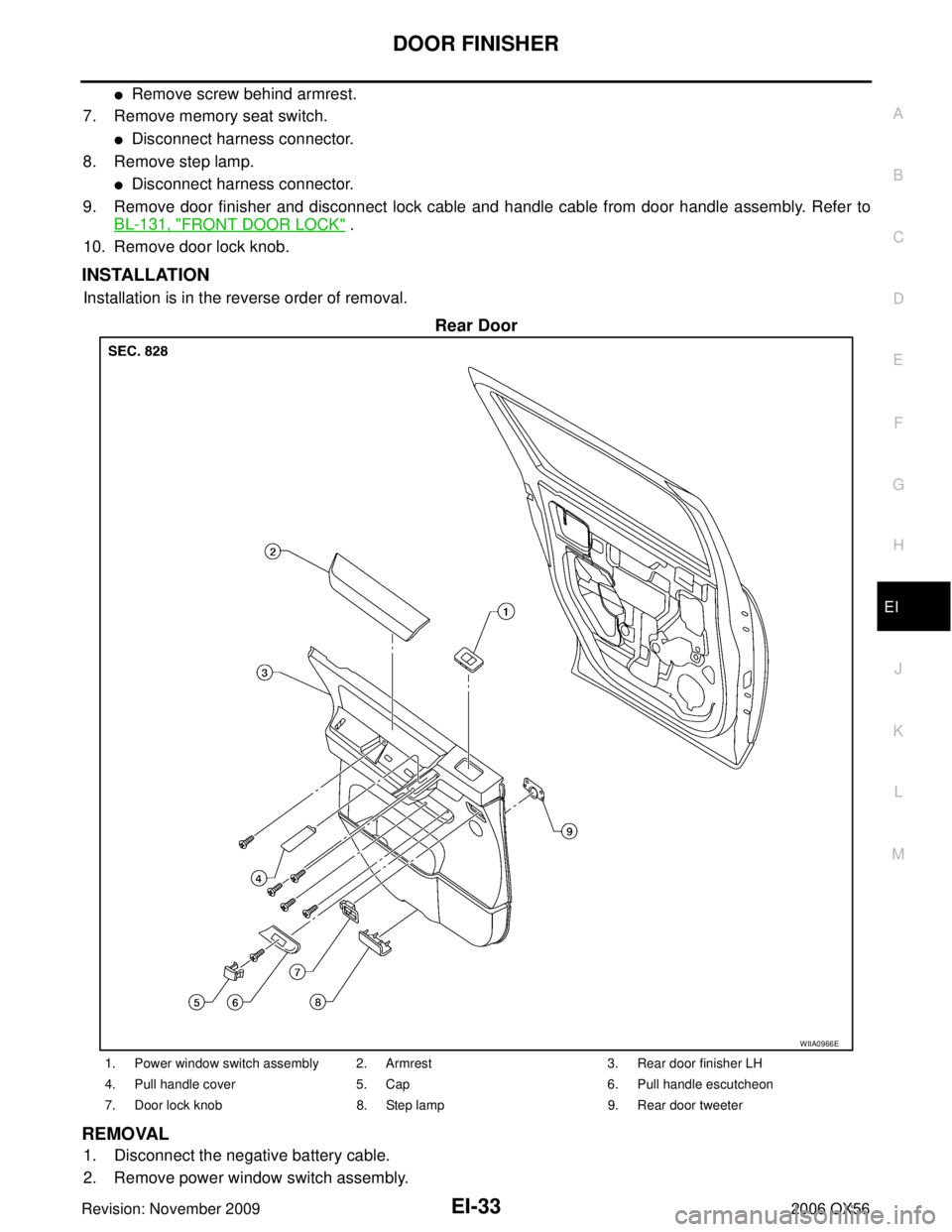
Rear Door
REMOVAL
1. Disconnect the negative battery cable.
2. Remove power window switch assembly.
WIIA0966E
1. Power window switch assembly 2. Armrest 3. Rear door finisher LH
4. Pull handle cover 5. Cap6. Pull handle escutcheon
7. Door lock knob 8. Step lamp9. Rear door tweeter
Page 1888 of 3383

HEADLININGEI-39
C
DE
F
G H
J
K L
M A
B
EI
Revision: November 2009 2006 QX56
CAUTION:
Disconnect both terminals from battery in advance.
REMOVAL
1. Disconnect the battery negative and positive cables, then wait at least 3 minutes.
2. Remove body side trim. Refer to EI-35, "
BODY SIDE TRIM" .
3. Remove luggage floor trim. Refer to EI-40, "
LUGGAGE FLOOR TRIM" .
4. Remove sunvisor assemblies.
5. Remove sunvisor clips.
6. Remove sunroof welt (if equipped).
7. Remove front roof console.
�Disconnect harnesses.
8. Remove rear roof console.
�Disconnect harnesses.
9. Remove assist grips.
10. Remove lamp assembly and rear roof finisher.
�Disconnect harness.
11. Remove headlining.
�Remove clips from rear of headlining.
�Disconnect harnesses.
12. Remove rear air control.
�Disconnect harness.
13. Remove rear audio control assembly.
�Disconnect harness.
14. Remove lamp assemblies.
�Disconnect harnesses.
15. Remove air vents.
16. Remove the front roof console bracket.
17. Remove rear roof console front bracket.
18. Remove assist grip brackets from roof.
INSTALLATION
Installation is in the reverse order of removal.
1. Headlining (without sunroof) 2. Assist grip bracket 3. Assist grip
4. Sunvisor assembly LH 5. Cap LH 6. Sunvisor holder
7. Front roof console 8. Sunglass bin9. Sunroof welt
10. Cap RH 11. Sunvisor assembly RH12. Rear roof console bracket
13. Rear storage bin or DVD display 14. Rear air control 15. Rear audio control assembly
16. Rear roof console 17. Rear roof console finisher18. Rear storage bin
19. Air vent 20. Lamp assembly21. Plastic clip
22. Headlining (with sunroof) 23. Rear lamp lens24. Rear lamp
25. Rear roof finisher 26. Plastic clip27. Metal clip
Page 1922 of 3383
FUEL INJECTOR AND FUEL TUBEEM-31
C
DE
F
G H
I
J
K L
M A
EM
Revision: November 2009 2006 QX56
FUEL INJECTOR AND FUEL TUBEPFP:16600
Removal and InstallationEBS00RF5
CAUTION:
Do not remove or disassemble parts unless instructed as shown.
REMOVAL
1. Remove the engine room cover using power tool. Refer to EM-12, "REMOVAL" .
2. Release the fuel pressure. Refer to EC-80, "
FUEL PRESSURE RELEASE" .
3. Disconnect the negative battery terminal.
4. Disconnect the fuel injector harness connectors.
5. Disconnect the fuel hose assembly from the fuel tubes (RH and LH).
CAUTION:
�While hoses are disconnected, plug them to prevent fuel from draining.
�Do not separate the fuel connector and fuel hose.
6. Remove the fuel injectors with the fuel tube assembly.
1. Fuel tube (RH) 2. Cap3. Fuel damper
4. O-ring 5. O-ring (blue)6. Fuel injector
7. Clip 8. O-ring (brown)9. O-ring
10. Fuel hose assembly 11. Fuel tube (LH)
KBIA2472E
Page 1947 of 3383

EM-56Revision: November 2009
CAMSHAFT
2006 QX56
1. Warm up the engine. Then stop the engine.
2. Remove the engine cover and. Refer to EM-12, "
Removal and Installation" .
3. Remove the battery cover. Refer to SC-9, "
Removal and Installation" .
4. Remove the air cleaner and air duct assembly EM-15, "
Removal and Installation" .
5. Remove the RH bank and LH bank rocker covers using power tool. Refer to EM-35, "
REMOVAL" .
6. Turn the crankshaft pulley in the normal direction (clockwise when viewed from engine front) to align TDC identification notch
(without paint mark) with timing indicator.
7. At this time, make sure both the intake and exhaust cam noses of No. 1 cylinder (top front on LH bank) face outside.
�If they do not face outside, turn crankshaft pulley once more.
8. Measure valve clearances at the locations marked “×” as shown
in the table below (locations indicated with black arrow).
�⇐ : Engine front
�⇐ (black): Measurable at No.1 cylinder compression top dead
center
�⇐ (white): Measurable at No. 3 cylinder compression top
dead center
�A: RH
�B: LH
�C: Exhaust
�D: Intake
NOTE:
Firing order 1-8-7-3-6-5-4-2
�No. 1 cylinder compression TDC
KBIA2476E
KBIA0400J
Measuring position (RH bank) No. 2 cyl
(E) No. 4 cyl
(F) No. 6 cyl
(G) No. 8 cyl
(H)
No. 1 cylinder at TDC EXH
×
INT ××
Measuring position (LH bank) No. 1 cyl
(J) No. 3 cyl
(K) No. 5 cyl
(L) No. 7 cyl
(M)
No. 1 cylinder at TDC INT
××
EXH ××
WBIA0713E
Page 1954 of 3383

CYLINDER HEADEM-63
C
DE
F
G H
I
J
K L
M A
EM
Revision: November 2009 2006 QX56
CYLINDER HEADPFP:11041
On-Vehicle ServiceEBS00RFD
CHECKING COMPRESSION PRESSURE
1. Warm up the engine thoroughly. Then stop the engine.
2. Release the fuel pressure. Refer to EC-80, "
FUEL PRESSURE RELEASE" .
CAUTION:
If CONSULT-II is not used to release fuel pressure leave the fuel pump fuse disconnected until
step 7.
3. Remove the spark plug from each cylinder. Refer to EM-29, "
Removal and Installation" .
4. Connect the engine tachometer (not required in use of CONSULT-II).
5. Install the compression tester with Tool into the spark plug hole.
6. With the accelerator pedal fully depressed, turn the ignition switch to “START” for cranking. When the gauge pointer stabi-
lizes, read the compression pressure and engine rpm. Perform
these steps to check each cylinder.
Unit: kPa (kg/cm2 , psi) /rpm
CAUTION:
Always use a fully charged battery to obtain specified engine speed.
�If the engine speed is out of the specified range, check the battery liquid for proper gravity. Check the
engine speed again with normal battery gravity.
�If the compression pressure is below the minimum value, check the valve clearances and parts associ-
ated with the combustion chamber (valve, valve seat, piston, piston ring, cylinder bore, cylinder head,
cylinder head gasket). After checking, measure the compression pressure again.
�If some cylinders have low compression pressure, pour a small amount of engine oil into the spark plug
hole of the cylinder to re-check it for compression.
–If the added engine oil improves the compression, the piston rings may be worn out or damaged. Check
the piston rings and replace if necessary.
–If the compression pressure remains at a low level despite the addition of engine oil, the valves may be
malfunctioning. Check the valves for damage. Replace the valve or valve seat accordingly.
�If two adjacent cylinders have respectively low compression pressure and their compression remains
low even after the addition of engine oil, the gaskets may be leaking, or a valve in adjacent cylinders
may be damaged. Inspect and repair as required.
7. Install the components in the reverse order of removal.
8. Start the engine and confirm that it runs smoothly.
9. Perform trouble diagnosis. If DTC appears, erase it. Refer to LAN-26, "
CAN COMMUNICATION" .
Tool number : EG15050500 (J-45402)
Standard
MinimumDeference limit
between cylinders
1,520 (15.5, 220) / 200 1,324 (13.5, 192) / 200 98 (1.0, 14) / 200
WBIA0605E