Page 1836 of 3383
IGNITION SIGNALEC-625
C
DE
F
G H
I
J
K L
M A
EC
Revision: November 2009 2006 QX56
3. CHECK OVERALL FUNCTION
Without CONSULT-II
1. Let engine idle.
2. Read the voltage signal between ECM terminals 46, 60, 61, 62, 65, 79, 80, 81 and ground with an oscilloscope.
3. Verify that the oscilloscope screen shows the signal wave as shown below.
NOTE:
The pulse cycle changes depending on rpm at idle.
OK or NG
OK >> INSPECTION END
NG >> GO TO 10.
4. CHECK IGNITION COIL POWER SUPPLY CIRCUIT-I
1. Turn ignition switch OFF, wait at least 10 seconds and then turn ON.
2. Check voltage between ECM terminals 119, 120 and ground with CONSULT-II or tester.
OK or NG
OK >> GO TO 5.
NG >> Go to EC-145, "
POWER SUPPLY AND GROUND CIR-
CUIT" .
PBIB2094E
PBIB0044E
Voltage: Battery voltage
MBIB0034E
Page 1837 of 3383

EC-626Revision: November 2009
IGNITION SIGNAL
2006 QX56
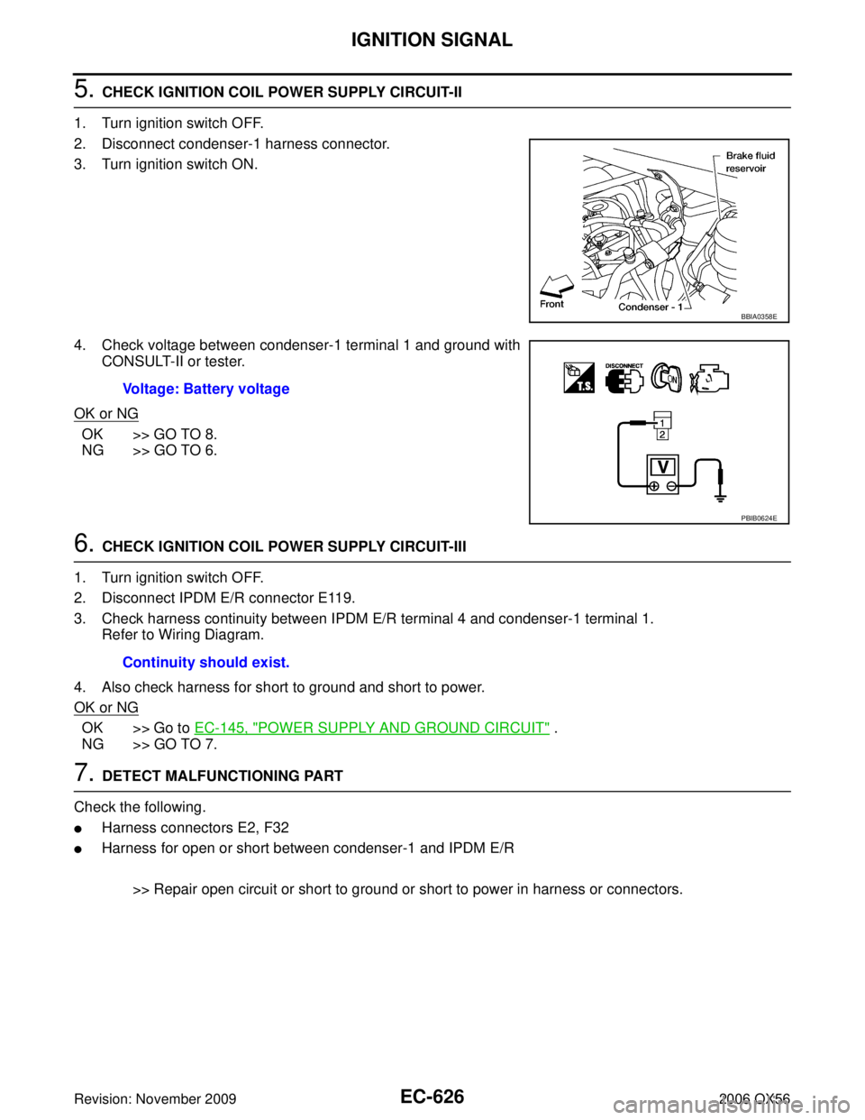
5. CHECK IGNITION COIL POWER SUPPLY CIRCUIT-II
1. Turn ignition switch OFF.
2. Disconnect condenser-1 harness connector.
3. Turn ignition switch ON.
4. Check voltage between condenser-1 terminal 1 and ground with CONSULT-II or tester.
OK or NG
OK >> GO TO 8.
NG >> GO TO 6.
6. CHECK IGNITION COIL POWER SUPPLY CIRCUIT-III
1. Turn ignition switch OFF.
2. Disconnect IPDM E/R connector E119.
3. Check harness continuity between IPDM E/R terminal 4 and condenser-1 terminal 1. Refer to Wiring Diagram.
4. Also check harness for short to ground and short to power.
OK or NG
OK >> Go to EC-145, "POWER SUPPLY AND GROUND CIRCUIT" .
NG >> GO TO 7.
7. DETECT MALFUNCTIONING PART
Check the following.
�Harness connectors E2, F32
�Harness for open or short between condenser-1 and IPDM E/R
>> Repair open circuit or short to ground or short to power in harness or connectors.
BBIA0358E
Voltage: Battery voltage
PBIB0624E
Continuity should exist.
Page 1838 of 3383

IGNITION SIGNALEC-627
C
DE
F
G H
I
J
K L
M A
EC
Revision: November 2009 2006 QX56
8. CHECK CONDENSER-1 GROUND CIRCUIT FOR OPEN AND SHORT
1. Turn ignition switch OFF.
2. Check harness continuity between condenser-1 terminal 2 and ground. Refer to Wiring Diagram.
3. Also check harness for short to power.
OK or NG
OK >> GO TO 9.
NG >> Repair open circuit or short to power in harness or connectors.
9. CHECK CONDENSER-1
Refer to EC-628, "
Component Inspection" .
OK or NG
OK >> GO TO 10.
NG >> Replace condenser-1.
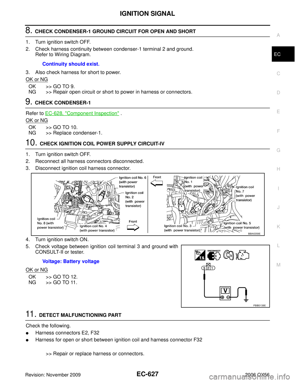
10. CHECK IGNITION COIL POWER SUPPLY CIRCUIT-IV
1. Turn ignition switch OFF.
2. Reconnect all harness connectors disconnected.
3. Disconnect ignition coil harness connector.
4. Turn ignition switch ON.
5. Check voltage between ignition coil terminal 3 and ground with CONSULT-II or tester.
OK or NG
OK >> GO TO 12.
NG >> GO TO 11.
11 . DETECT MALFUNCTIONING PART
Check the following.
�Harness connectors E2, F32
�Harness for open or short between ignition coil and harness connector F32
>> Repair or replace harness or connectors.
Continuity should exist.
Voltage: Battery voltage
BBIA0359E
PBIB0138E
Page 1848 of 3383

SERVICE DATA AND SPECIFICATIONS (SDS)EC-637
C
DE
F
G H
I
J
K L
M A
EC
Revision: November 2009 2006 QX56
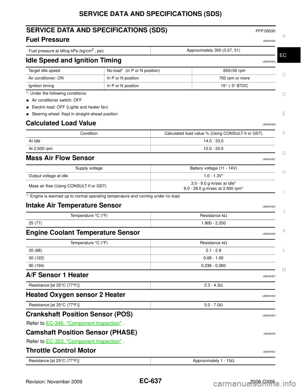
SERVICE DATA AND SPECIFICATIONS (SDS)PFP:00030
Fuel PressureUBS00HE9
Idle Speed and Ignition TimingUBS00HEA
*: Under the following conditions:
�Air conditioner switch: OFF
�Electric load: OFF (Lights and heater fan)
�Steering wheel: Kept in straight-ahead position
Calculated Load ValueUBS00HEB
Mass Air Flow SensorUBS00HEC
*: Engine is warmed up to normal operating temperature and running under no load.
Intake Air Temperature SensorUBS00HED
Engine Coolant Temperature SensorUBS00HEE
A/F Sensor 1 HeaterUBS00HEF
Heated Oxygen sensor 2 HeaterUBS00HEG
Crankshaft Position Sensor (POS)UBS00HEH
Refer to EC-346, "Component Inspection" .
Camshaft Position Sensor (PHASE)UBS00HEI
Refer to EC-353, "Component Inspection" .
Throttle Control MotorUBS00HEJ
Fuel pressure at idling kPa (kg/cm2 , psi) Approximately 350 (3.57, 51)
Target idle speed
No-load* (in P or N position) 650±50 rpm
Air conditioner: ON In P or N position 700 rpm or more
Ignition timing In P or N position 15° ± 5 ° BTDC
Condition Calculated load value % (Using CONSULT-II or GST)
At idle 14.0 - 33.0
At 2,500 rpm 12.0 - 25.0
Supply voltageBattery voltage (11 - 14V)
Output voltage at idle 1.0 - 1.3V*
Mass air flow (Using CONSULT-II or GST) 3.0 - 9.0 g
·m/sec at idle*
9.0 - 28.0 g· m/sec at 2,500 rpm*
Temperature °C (°F) Resistance kΩ
25 (77) 1.800 - 2.200
Temperature °C (°F) Resistance kΩ
20 (68) 2.1 - 2.9
50 (122) 0.68 - 1.00
90 (194) 0.236 - 0.260
Resistance [at 25°C (77 °F)] 2.3 - 4.3Ω
Resistance [at 25 °C (77 °F)] 5.0 - 7.0Ω
Resistance [at 25 °C (77 °F)] Approximately 1 - 15Ω
Page 1862 of 3383
FRONT BUMPEREI-13
C
DE
F
G H
J
K L
M A
B
EI
Revision: November 2009 2006 QX56
FRONT BUMPERPFP:F2022
Removal and InstallationEIS004WD
REMOVAL
1. Disconnect the negative battery cable.
2. Remove side screws from front fascia assembly.
1. Lower energy absorber2. Front bumper side bracket RH 3. Front bumper stay RH
4. Upper bumper reinforcement 5. Clip C103 6. Upper energy absorber (part of
upper bumper reinforcement)
7. Clip CS101 8. Front fascia assembly9. Engine undercover
10. Front fascia bracket 11. License plate bracket12. Fog turn/fog lamp finisher LH/RH
13. Fog turn/fog lamp 14. Front bumper stay LH15. Front bumper side bracket LH
16. Headlamp finisher (RH shown)
WIIA0952E
Page 1865 of 3383

EI-16
REAR BUMPER
Revision: November 20092006 QX56
REMOVAL
1. Disconnect the negative battery cable.
2. Remove quarter panel trim covers LH and RH.
3. Disconnect sonar sensor harness connector under rear fascia assembly.
4. Release retainer clips on both sides of rear fascia assembly with a 1/4 turn and top S clips and remove
fascia assembly.
5. Remove energy absorber.
6. Remove reinforcement assembly.
7. Remove nuts and remove retainer assembly.
�Remove S clips from retainer assembly.
8. Disconnect sonar sensors from sonar sensor retainers.
9. Remove sonar sensors and harness from rear fascia assembly.
�Disconnect sonar sensors from harness.
�Remove sonar sensor retainers from rear fascia assembly.
10. Remove bolts on each side of tow hitch and remove tow hitch.
11. Remove drafter duct from under LH quarter panel.
INSTALLATION
Installation is in the reverse order of removal.
1. Retainer assembly 2. Clip C103 3. S clip
4. Reinforcement assembly 5. Energy absorber 6. Sonar sensor
7. Quarter panel trim cover LH 8. Drafter duct 9. Retainer clip
10. Rear fascia assembly 11. Sonar sensor retainer 12. Tow hitch
13. Sonar sensor harness 14. Quarter panel trim cover RH
Page 1867 of 3383
EI-18
COWL TOP
Revision: November 20092006 QX56
COWL TOPPFP:66100
Removal and InstallationEIS004WG
REMOVAL
1. Disconnect the negative and positive battery cables, then wait at least 3 minutes.
2. Remove right and left wiper arms. Refer to WW-28, "
Front Wiper Arms" .
3. Remove cowl top seal.
�Release plastics clips on cowl top seal which go through cowl tops LH and RH and cowl top extension.
4. Remove cowl top covers LH and RH.
�Release plastic clips under cowl top covers attaching to grommets on hoodledge.
�Disconnect washer tubes from washer nozzles under cowl top covers.
5. Remove cowl top extension brackets LH and RH.
�Disconnect wiper motor harness from cowl top extension bracket LH.
1. Clip CG104 2. Clip C103 3. Cowl top cover RH
4. Cowl top seal 5. Drain tube 6. Cowl top extension bracket RH
7. Cowl top extension 8. Cowl top extension bracket LH 9. Cowl top cover LH
WIIA0955E
Page 1873 of 3383
EI-24
LICENSE LAMP FINISHER
Revision: November 20092006 QX56
LICENSE LAMP FINISHERPFP:84810
Removal and InstallationEIS004WK
REMOVAL
1. Disconnect the negative and positive battery cables, then wait at least 3 minutes.
2. Remove back door trim. Refer to EI-42, "
BACK DOOR TRIM" .
3. Disconnect harness connectors and remove with bulbs from license lamps.
4. Remove nuts and screws from license lamp finisher.
5. Release clips and remove license lamp finisher.
INSTALLATION
Installation is in the reverse order of removal.
1. Seal 2. Plastic clip 3. Nut
4. License lamp finisher 5. Clip CS101 6. Seal
WIIA0959E