2006 INFINITI M35 brake
[x] Cancel search: brakePage 3438 of 5621
![INFINITI M35 2006 Factory Service Manual COIL SPRING AND SHOCK ABSORBER
FSU-11
[2WD]
C
D
F
G
H
I
J
K
L
MA
B
FSU
Revision: 2006 January2006 M35/M45
COIL SPRING AND SHOCK ABSORBERPFP:55302
Removal and InstallationNES000IE
REMOVAL
1. Remove tir INFINITI M35 2006 Factory Service Manual COIL SPRING AND SHOCK ABSORBER
FSU-11
[2WD]
C
D
F
G
H
I
J
K
L
MA
B
FSU
Revision: 2006 January2006 M35/M45
COIL SPRING AND SHOCK ABSORBERPFP:55302
Removal and InstallationNES000IE
REMOVAL
1. Remove tir](/manual-img/42/57023/w960_57023-3437.png)
COIL SPRING AND SHOCK ABSORBER
FSU-11
[2WD]
C
D
F
G
H
I
J
K
L
MA
B
FSU
Revision: 2006 January2006 M35/M45
COIL SPRING AND SHOCK ABSORBERPFP:55302
Removal and InstallationNES000IE
REMOVAL
1. Remove tires from vehicle with a power tool.
2. Remove harness of wheel sensor from shock absorber. Refer to BRC-57, "
WHEEL SENSOR" .
CAUTION:
Do not pull on wheel sensor harness.
3. Remove brake hose bracket. Refer to BR-12, "
BRAKE TUBE AND HOSE" .
4. Remove the mounting nut on the upper side of stabilizer connecting rod with a power tool, and then
remove stabilizer connecting rod from transverse link.
5. Remove mounting nut and bolt on the lower side of shock absorber with a power tool, and then remove
shock absorber from transverse link.
6. Remove cotter pin of transverse link and steering knuckle, and then loosen nut.
7. Remove transverse link from steering knuckle so as not to damage ball joint boot using the ball joint
remover (suitable tool).
CAUTION:
Temporarily tighten the nut to prevent damage to threads and to prevent ball joint remover (suit-
able tool) from suddenly coming off.
8. Remove the mounting nuts of shock absorber mounting bracket, then remove shock absorber from vehi-
cle.
INSTALLATION
Installation is the reverse order of removal. For tightening torque, refer to FSU-8, "Components" .
Perform final tightening of bolt and nut at the shock absorber lower side (rubber bushing), under unladen
conditions with tires on level ground. Check wheel alignment. Refer to FSU-6, "
Wheel Alignment Inspec-
tion" .
Adjust neutral position of steering angle sensor after checking wheel alignment. Refer to BRC-6, "Adjust-
ment of Steering Angle Sensor Neutral Position" .
Check wheel sensor harness for proper connection. Refer to BRC-57, "WHEEL SENSOR" .
Disassembly and AssemblyNES000IF
DISASSEMBLY
CAUTION:
Do not damage shock absorber piston rod when removing components from shock absorber.
1. Install strut attachment [SST] to shock absorber and secure it in
a vise.
CAUTION:
When installing the strut attachment to shock absorber,
wrap a shop cloth around strut to protect it from damage.
SEIA0296E
Page 3449 of 5621
![INFINITI M35 2006 Factory Service Manual FSU-22
[AWD]
NOISE, VIBRATION AND HARSHNESS (NVH) TROUBLESHOOTING
Revision: 2006 January2006 M35/M45
NOISE, VIBRATION AND HARSHNESS (NVH) TROUBLESHOOTINGPFP:00003
NVH Troubleshooting ChartNES000IP
Use INFINITI M35 2006 Factory Service Manual FSU-22
[AWD]
NOISE, VIBRATION AND HARSHNESS (NVH) TROUBLESHOOTING
Revision: 2006 January2006 M35/M45
NOISE, VIBRATION AND HARSHNESS (NVH) TROUBLESHOOTINGPFP:00003
NVH Troubleshooting ChartNES000IP
Use](/manual-img/42/57023/w960_57023-3448.png)
FSU-22
[AWD]
NOISE, VIBRATION AND HARSHNESS (NVH) TROUBLESHOOTING
Revision: 2006 January2006 M35/M45
NOISE, VIBRATION AND HARSHNESS (NVH) TROUBLESHOOTINGPFP:00003
NVH Troubleshooting ChartNES000IP
Use chart below to help you find the cause of the symptom. If necessary, repair or replace these parts.
: ApplicableReference page
FSU-25FSU-29
—
—
—
FSU-25
FSU-23FSU-35
NVH in PR section
NVH in RFD section
NVH in FAX and FSU section
NVH in WT section
NVH in FAX section
NVH in BR section
NVH in PS section
Possible cause and SUSPECTED PARTS
Improper installation, looseness
Strut deformation, damage or deflection
Bushing or mounting deterioration
Parts interference
Spring fatigue
Suspension looseness
Incorrect wheel alignment
Stabilizer bar fatigue
PROPELLER SHAFT
DIFFERENTIAL
FRONT AXLE AND FRONT SUSPENSION
ROAD WHEEL
DRIVE SHAFT
BRAKES
STEERING
Symptom FRONT SUSPENSIONNoise
Shake
Vibration
Shimmy
Judder
Poor quality ride or handling
Page 3450 of 5621
![INFINITI M35 2006 Factory Service Manual FRONT SUSPENSION ASSEMBLY
FSU-23
[AWD]
C
D
F
G
H
I
J
K
L
MA
B
FSU
Revision: 2006 January2006 M35/M45
FRONT SUSPENSION ASSEMBLYPFP:54010
On-Vehicle Inspection and ServiceNES000IQ
Make sure the mount INFINITI M35 2006 Factory Service Manual FRONT SUSPENSION ASSEMBLY
FSU-23
[AWD]
C
D
F
G
H
I
J
K
L
MA
B
FSU
Revision: 2006 January2006 M35/M45
FRONT SUSPENSION ASSEMBLYPFP:54010
On-Vehicle Inspection and ServiceNES000IQ
Make sure the mount](/manual-img/42/57023/w960_57023-3449.png)
FRONT SUSPENSION ASSEMBLY
FSU-23
[AWD]
C
D
F
G
H
I
J
K
L
MA
B
FSU
Revision: 2006 January2006 M35/M45
FRONT SUSPENSION ASSEMBLYPFP:54010
On-Vehicle Inspection and ServiceNES000IQ
Make sure the mounting conditions (looseness, back lash) of each component and component conditions
(wear, damage) are normal.
INSPECTION OF LOWER BALL JOINT END PLAY
1. Set front wheels in a straight-ahead position. Do not depress brake pedal.
2. Place an iron bar or similar tool between transverse link and steering knuckle.
3. Measure axial end play by prying it up and down.
CAUTION:
Be careful not to damage ball joint boot. Do not damage the installation position by applying
excessive force.
SHOCK ABSORBER INSPECTION
Check for oil leakage, damage and breakage of installation positions.
Wheel Alignment InspectionNES000IR
DESCRIPTION
Measure wheel alignment under unladen conditions.
NOTE:
“Unladen conditions” means that fuel, engine coolant, and lubricant are full. Spare tire, jack, hand tools and
mats are in designated positions.
PRELIMINARY CHECK
Check the following:
1. Tires for improper air pressure and wear.
2. Road wheels for runout. Refer to WT-6, "
ROAD WHEEL" .
3. Wheel bearing axial end play. Refer to FAX-5, "
WHEEL BEARING INSPECTION" .
4. Transverse link ball joint axial end play. Refer to FSU-31, "
INSPECTION AFTER REMOVAL" .
5. Shock absorber operation.
6. Each mounting part of axle and suspension for looseness and deformation.
7. Each of suspension member, shock absorber, upper link and transverse link for cracks, deformation and
other damage.
8. Vehicle height (posture).
GENERAL INFORMATION AND RECOMMENDATIONS
A four-wheel thrust alignment should be performed.
–This type of alignment is recommended for any NISSAN/INFINITI vehicle.
–The four-wheel “thrust” process helps ensure that the vehicle is properly aligned and the steering wheel is
centered.
–The alignment rack itself should be capable of accepting any NISSAN/INFINITI vehicle.
–The rack should be checked to ensure that it is level.
Make sure the machine is properly calibrated.
–Your alignment equipment should be regularly calibrated in order to give correct information.
–Check with the manufacturer of your specific equipment for their recommended Service/Calibration
Schedule.Axial end play : 0 mm (0 in)
Page 3453 of 5621
![INFINITI M35 2006 Factory Service Manual FSU-26
[AWD]
FRONT SUSPENSION ASSEMBLY
Revision: 2006 January2006 M35/M45
Refer to GI section for symbol marks in the figure. Refer to GI-9, "HOW TO USE THIS MANUAL" .
Removal and Installation INFINITI M35 2006 Factory Service Manual FSU-26
[AWD]
FRONT SUSPENSION ASSEMBLY
Revision: 2006 January2006 M35/M45
Refer to GI section for symbol marks in the figure. Refer to GI-9, "HOW TO USE THIS MANUAL" .
Removal and Installation](/manual-img/42/57023/w960_57023-3452.png)
FSU-26
[AWD]
FRONT SUSPENSION ASSEMBLY
Revision: 2006 January2006 M35/M45
Refer to GI section for symbol marks in the figure. Refer to GI-9, "HOW TO USE THIS MANUAL" .
Removal and Installation NES000IT
REMOVAL
1. Remove cowl top panel and hood. Refer to EI-18, "COWL TOP" , EI-17, "HOOD" .
2. Install engine slinger, and then hoist engine. Refer to EM-118, "
Removal and Installation (AWD Models)" .
3. Remove tires from vehicle with a power tool.
4. Remove wheel sensor from steering knuckle. Refer to BRC-57, "
WHEEL SENSOR" .
CAUTION:
Do not pull on wheel sensor harness.
5. Remove brake hose bracket. Refer to BR-12, "
BRAKE TUBE AND HOSE" .
6. Remove undercover with a power tool.
7. Remove cotter pin (1), and then loosen the nut.
8. Remove steering outer socket (2) from steering knuckle (3) so
as not to damage ball joint boot (4) using the ball joint remover
(suitable tool).
CAUTION:
Temporarily tighten the nut to prevent damage to threads
and to prevent the ball joint remover (suitable tool) from
suddenly coming off.
9. Remove the mounting nut on the upper side of stabilizer con-
necting rod with a power tool, and then remove stabilizer con-
necting rod from transverse link.
10. Separate steering gear assembly and lower joint. Refer to PS-13, "
STEERING COLUMN" .
11. Remove front cross bar. Refer to FSU-25, "
Components" .
12. Remove steering hydraulic piping bracket from front suspension member. Refer to PS-38, "
HYDRAULIC
LINE" .
13. Remove the mounting nut and bolt on the lower side of shock absorber arm with a power tool, and then
remove shock absorber arm from transverse link.
14. Remove cotter pin of transverse link and steering knuckle, and then loosen nut.
15. Remove transverse link from steering knuckle so as not to damage ball joint boot using the ball joint
remover (suitable tool).
CAUTION:
Temporarily tighten the nut to prevent damage to threads and to prevent ball joint remover (suit-
able tool) from suddenly coming off.
16. Set jack under front suspension member.
17. Remove the mounting nuts of engine mounting insulator. Refer to EM-113, "
ENGINE ASSEMBLY" .
18. Remove the mounting bolts of member bracket, and then remove member bracket from front suspension
member with a power tool. Refer to FSU-25, "
Components" .
19. Remove the mounting nuts of front suspension member with a power tool. Refer to FSU-25, "
Compo-
nents" .
20. Gradually lower a jack to remove front suspension assembly from vehicle.
INSTALLATION
Installation is the reverse order of removal. For tightening torque, refer to FSU-25, "Components" .
1. Shock absorber mounting bracket 2. Bound bumper 3. Rubber seat
4. Coil spring 5. Shock absorber 6. Shock absorber arm
7. Upper link 8. Steering knuckle 9. Transverse link
10. Steering stopper bracket 11. Washer 12. Stabilizer connecting rod
13. Stabilizer bar 14. Stabilizer bushing 15. Stabilizer clamp
16. Front suspension member 17. Front cross bar 18. Member bracket
19. Clamp 20. Cotter pin 21. Stopper rubber
SGIA1183E
Page 3455 of 5621
![INFINITI M35 2006 Factory Service Manual FSU-28
[AWD]
COIL SPRING AND SHOCK ABSORBER
Revision: 2006 January2006 M35/M45
COIL SPRING AND SHOCK ABSORBERPFP:55302
Removal and InstallationNES000IU
REMOVAL
1. Remove tires from vehicle with a powe INFINITI M35 2006 Factory Service Manual FSU-28
[AWD]
COIL SPRING AND SHOCK ABSORBER
Revision: 2006 January2006 M35/M45
COIL SPRING AND SHOCK ABSORBERPFP:55302
Removal and InstallationNES000IU
REMOVAL
1. Remove tires from vehicle with a powe](/manual-img/42/57023/w960_57023-3454.png)
FSU-28
[AWD]
COIL SPRING AND SHOCK ABSORBER
Revision: 2006 January2006 M35/M45
COIL SPRING AND SHOCK ABSORBERPFP:55302
Removal and InstallationNES000IU
REMOVAL
1. Remove tires from vehicle with a power tool.
2. Remove harness of wheel sensor from shock absorber. Refer to BRC-57, "
WHEEL SENSOR" .
CAUTION:
Do not pull on wheel sensor harness.
3. Remove brake hose bracket. Refer to BR-12, "
BRAKE TUBE AND HOSE" .
4. Remove the mounting nut on the upper side of stabilizer connecting rod with a power tool, and then
remove stabilizer connecting rod from transverse link.
5. Remove mounting nut and bolt on the lower side of shock absorber arm with a power tool, and then
remove shock absorber arm from transverse link.
6. Remove cotter pin of transverse link and steering knuckle, and then loosen nut.
7. Remove transverse link from steering knuckle so as not to damage ball joint boot using the ball joint
remover (suitable tool).
CAUTION:
Temporarily tighten the nut to prevent damage to threads and to prevent ball joint remover (suit-
able tool) from suddenly coming off.
8. Remove the mounting bolt on the upper side of shock absorber arm with a power tool, and then remove
shock absorber arm from shock absorber.
9. Remove the mounting nuts of shock absorber mounting bracket, then remove shock absorber from vehi-
cle.
INSTALLATION
Installation is the reverse order of removal. For tightening torque, refer to FSU-25, "Components" .
Perform final tightening of bolt and nut at the shock absorber arm lower side (rubber bushing) under
unladen conditions with tires on level ground. Check wheel alignment. Refer to FSU-23, "
Wheel Align-
ment Inspection" .
Adjust neutral position of steering angle sensor after checking wheel alignment. Refer to BRC-6, "Adjust-
ment of Steering Angle Sensor Neutral Position" .
Check wheel sensor harness for proper connection. Refer to BRC-57, "WHEEL SENSOR" .
Disassembly and AssemblyNES000IV
DISASSEMBLY
CAUTION:
Do not damage shock absorber piston rod when removing components from shock absorber.
1. Install strut attachment [SST] to shock absorber and secure it in
a vise.
CAUTION:
When installing the strut attachment to shock absorber,
wrap a shop cloth around strut to protect it from damage.
SEIA0296E
Page 3468 of 5621

PRECAUTIONS
GI-5
C
D
E
F
G
H
I
J
K
L
MB
GI
Revision: 2006 January2006 M35/M45
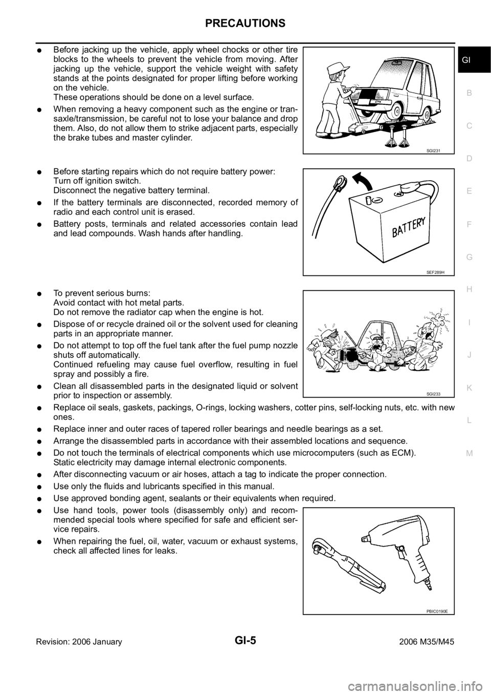
Before jacking up the vehicle, apply wheel chocks or other tire
blocks to the wheels to prevent the vehicle from moving. After
jacking up the vehicle, support the vehicle weight with safety
stands at the points designated for proper lifting before working
on the vehicle.
These operations should be done on a level surface.
When removing a heavy component such as the engine or tran-
saxle/transmission, be careful not to lose your balance and drop
them. Also, do not allow them to strike adjacent parts, especially
the brake tubes and master cylinder.
Before starting repairs which do not require battery power:
Turn off ignition switch.
Disconnect the negative battery terminal.
If the battery terminals are disconnected, recorded memory of
radio and each control unit is erased.
Battery posts, terminals and related accessories contain lead
and lead compounds. Wash hands after handling.
To prevent serious burns:
Avoid contact with hot metal parts.
Do not remove the radiator cap when the engine is hot.
Dispose of or recycle drained oil or the solvent used for cleaning
parts in an appropriate manner.
Do not attempt to top off the fuel tank after the fuel pump nozzle
shuts off automatically.
Continued refueling may cause fuel overflow, resulting in fuel
spray and possibly a fire.
Clean all disassembled parts in the designated liquid or solvent
prior to inspection or assembly.
Replace oil seals, gaskets, packings, O-rings, locking washers, cotter pins, self-locking nuts, etc. with new
ones.
Replace inner and outer races of tapered roller bearings and needle bearings as a set.
Arrange the disassembled parts in accordance with their assembled locations and sequence.
Do not touch the terminals of electrical components which use microcomputers (such as ECM).
Static electricity may damage internal electronic components.
After disconnecting vacuum or air hoses, attach a tag to indicate the proper connection.
Use only the fluids and lubricants specified in this manual.
Use approved bonding agent, sealants or their equivalents when required.
Use hand tools, power tools (disassembly only) and recom-
mended special tools where specified for safe and efficient ser-
vice repairs.
When repairing the fuel, oil, water, vacuum or exhaust systems,
check all affected lines for leaks.
SGI231
SEF289H
SGI233
PBIC0190E
Page 3474 of 5621

HOW TO USE THIS MANUAL
GI-11
C
D
E
F
G
H
I
J
K
L
MB
GI
Revision: 2006 January2006 M35/M45
ComponentsNAS0007L
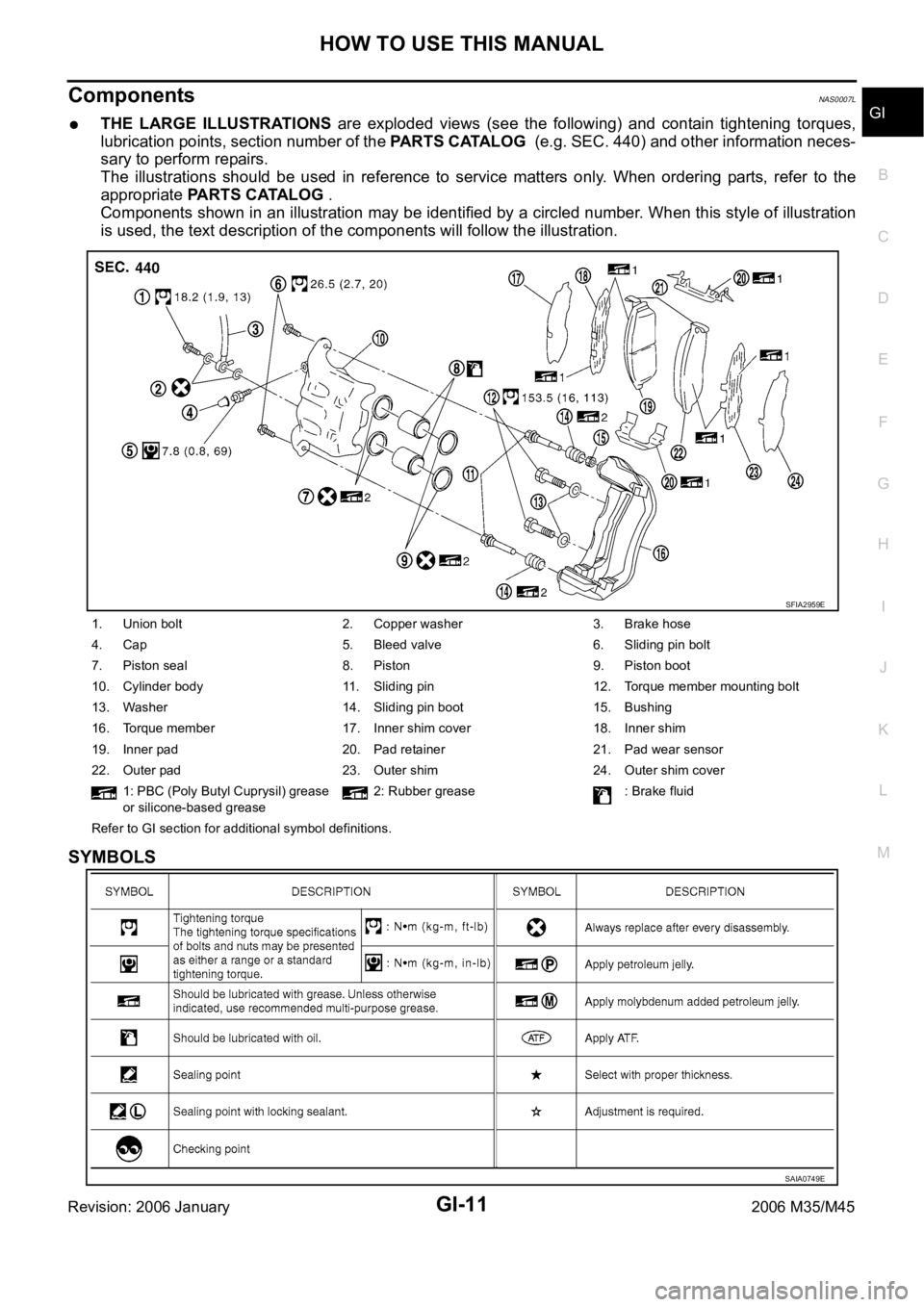
THE LARGE ILLUSTRATIONS are exploded views (see the following) and contain tightening torques,
lubrication points, section number of the PARTS CATALOG (e.g. SEC. 440) and other information neces-
sary to perform repairs.
The illustrations should be used in reference to service matters only. When ordering parts, refer to the
appropriate PARTS CATALOG .
Components shown in an illustration may be identified by a circled number. When this style of illustration
is used, the text description of the components will follow the illustration.
SYMBOLS
1. Union bolt 2. Copper washer 3. Brake hose
4. Cap 5. Bleed valve 6. Sliding pin bolt
7. Piston seal 8. Piston 9. Piston boot
10. Cylinder body 11. Sliding pin 12. Torque member mounting bolt
13. Washer 14. Sliding pin boot 15. Bushing
16. Torque member 17. Inner shim cover 18. Inner shim
19. Inner pad 20. Pad retainer 21. Pad wear sensor
22. Outer pad 23. Outer shim 24. Outer shim cover
1: PBC (Poly Butyl Cuprysil) grease
or silicone-based grease2: Rubber grease : Brake fluid
Refer to GI section for additional symbol definitions.
SFIA2959E
SAIA0749E
Page 3483 of 5621

GI-20
HOW TO USE THIS MANUAL
Revision: 2006 January2006 M35/M45
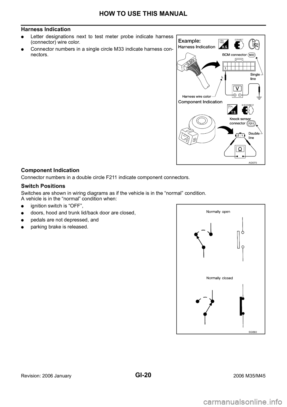
Harness Indication
Letter designations next to test meter probe indicate harness
(connector) wire color.
Connector numbers in a single circle M33 indicate harness con-
nectors.
Component Indication
Connector numbers in a double circle F211 indicate component connectors.
Switch Positions
Switches are shown in wiring diagrams as if the vehicle is in the “normal” condition.
A vehicle is in the “normal” condition when:
ignition switch is “OFF”,
doors, hood and trunk lid/back door are closed,
pedals are not depressed, and
parking brake is released.
AGI070
SGI860