2006 INFINITI M35 brake
[x] Cancel search: brakePage 4786 of 5621
PERIODIC MAINTENANCE
MA-9
C
D
E
F
G
H
I
J
K
MA
B
MA
Revision: 2006 January2006 M35/M45
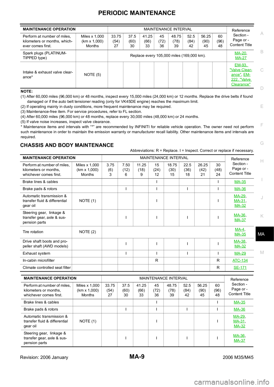
NOTE:
(1) After 60,000 miles (96,000 km) or 48 months, inspect every 15,000 miles (24,000 km) or 12 months. Replace the drive belts if found
damaged or if the auto belt tensioner reading (only for VK45DE engine) reaches the maximum limit.
(2) If operating mainly in dusty conditions, more frequent maintenance may be required.
(3) Maintenance-free item. For service procedures, refer to FL section.
(4) After 60,000 miles (96,000 km) or 48 months, replace every 30,000 miles (48,000 km) or 24 months.
(5) If valve noise increases, inspect valve clearance.
* Maintenance items and intervals with “*” are recommended by INFINITI for reliable vehicle operation. The owner need not perform
such maintenance in order to maintain the emission warranty or manufacturer recall liability. Other maintenance items and intervals are
required.
CHASSIS AND BODY MAINTENANCE
Abbreviations: R = Replace. I = Inspect. Correct or replace if necessary. Spark plugs (PLATINUM-
TIPPED type)Replace every 105,000 miles (169,000 km).MA-20
,
MA-27
Intake & exhaust valve clear-
ance*NOTE (5)EM-93, "Valve Clear-
ance", EM-
222, "Va l v e
Clearance"
MAINTENANCE OPERATIONMAINTENANCE INTERVAL
Reference
Section -
Page or -
Content Title Perform at number of miles,
kilometers or months, which-
ever comes first.Miles x 1,000
(km x 1,000)
Months33.75
(54)
2737.5
(60)
3041.25
(66)
3345
(72)
3648.75
(78)
3952.5
(84)
4256.25
(90)
4560
(96)
48
MAINTENANCE OPERATIONMAINTENANCE INTERVAL
Reference
Section -
Page or -
Content Title Perform at number of miles,
kilometers or months,
whichever comes first.Miles x 1,000
(km x 1,000)
Months3.75
(6)
37.50
(12)
611 . 2 5
(18)
915
(24)
1218.75
(30)
1522.5
(36)
1826.25
(42)
2130
(48)
24
Brake lines & cables I IMA-35
Brake pads & rotors I I I IMA-36
Automatic transmission &
transfer fluid & differential
gear oilNOTE (1) I IMA-29,
MA-31
,
MA-32
Steering gear, linkage &
transfer gear, axle & sus-
pension partsIIIIMA-36,
MA-37
Tire rotation NOTE (2)MA-4,
MA-35
Drive shaft boots and pro-
peller shaft (AWD models) IIIIMA-38,
MA-32
Exhaust system I I I IMA-29
In-cabin microfilter R RAT C - 1 3 4
Climate controlled seat filterRSE-171
MAINTENANCE OPERATIONMAINTENANCE INTERVAL
Reference
Section -
Page or -
Content Title Perform at number of miles,
kilometers or months,
whichever comes first.Miles x 1,000
(km x 1,000)
Months33.75
(54)
2737.5
(60)
3041.25
(66)
3345
(72)
3648.75
(78)
3952.5
(84)
4256.25
(90)
4560
(96)
48
Brake lines & cables I IMA-35
Brake pads & rotors I I I IMA-36
Automatic transmission &
transfer fluid & differential
gear oilNOTE (1) I IMA-29,
MA-31
,
MA-32
Steering gear, linkage &
transfer gear, axle & sus-
pension partsI IIIMA-36,
MA-37
Page 4788 of 5621
PERIODIC MAINTENANCE
MA-11
C
D
E
F
G
H
I
J
K
MA
B
MA
Revision: 2006 January2006 M35/M45
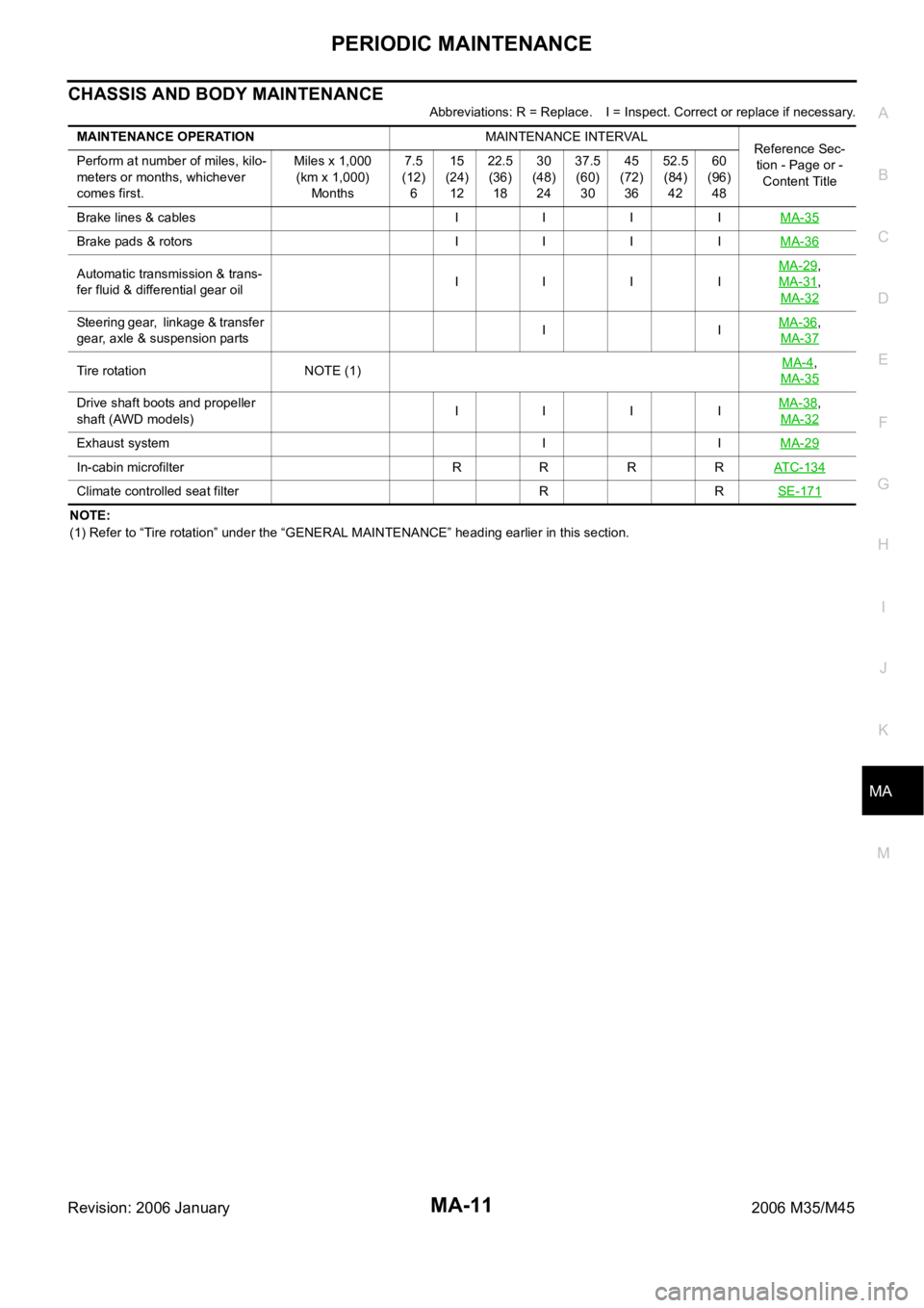
CHASSIS AND BODY MAINTENANCE
Abbreviations: R = Replace. I = Inspect. Correct or replace if necessary.
NOTE:
(1) Refer to “Tire rotation” under the “GENERAL MAINTENANCE” heading earlier in this section. MAINTENANCE OPERATIONMAINTENANCE INTERVAL
Reference Sec-
tion - Page or -
Content Title Perform at number of miles, kilo-
meters or months, whichever
comes first.Miles x 1,000
(km x 1,000)
Months7.5
(12)
615
(24)
1222.5
(36)
1830
(48)
2437.5
(60)
3045
(72)
3652.5
(84)
4260
(96)
48
Brake lines & cables I I I IMA-35
Brake pads & rotors I I I IMA-36
Automatic transmission & trans-
fer fluid & differential gear oilIIIIMA-29,
MA-31
,
MA-32
Steering gear, linkage & transfer
gear, axle & suspension partsIIMA-36,
MA-37
Tire rotation NOTE (1)MA-4,
MA-35
Drive shaft boots and propeller
shaft (AWD models) IIIIMA-38,
MA-32
Exhaust system I IMA-29
In-cabin microfilter R R R RATC-134
Climate controlled seat filter R RSE-171
Page 4789 of 5621
MA-12
RECOMMENDED FLUIDS AND LUBRICANTS
Revision: 2006 January2006 M35/M45
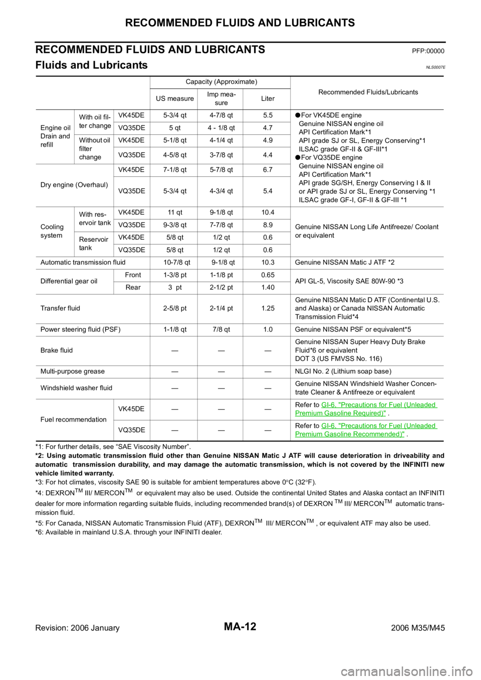
RECOMMENDED FLUIDS AND LUBRICANTSPFP:00000
Fluids and Lubricants NLS0007E
*1: For further details, see “SAE Viscosity Number”.
*2: Using automatic transmission fluid other than Genuine NISSAN Matic J ATF will cause deterioration in driveability and
automatic transmission durability, and may damage the automatic transmission, which is not covered by the INFINITI new
vehicle limited warranty.
*3: For hot climates, viscosity SAE 90 is suitable for ambient temperatures above 0
C (32F).
*4: DEXRONTM III/ MERCONTM or equivalent may also be used. Outside the continental United States and Alaska contact an INFINITI
dealer for more information regarding suitable fluids, including recommended brand(s) of DEXRON TM III/ MERCONTM automatic trans-
mission fluid.
*5: For Canada, NISSAN Automatic Transmission Fluid (ATF), DEXRON
TM III/ MERCONTM , or equivalent ATF may also be used.
*6: Available in mainland U.S.A. through your INFINITI dealer.Capacity (Approximate)
Recommended Fluids/Lubricants
US measureImp mea-
sureLiter
Engine oil
Drain and
refillWith oil fil-
ter changeVK45DE 5-3/4 qt 4-7/8 qt 5.5
For VK45DE engine
Genuine NISSAN engine oil
API Certification Mark*1
API grade SJ or SL, Energy Conserving*1
ILSAC grade GF-II & GF-III*1
For VQ35DE engine
Genuine NISSAN engine oil
API Certification Mark*1
API grade SG/SH, Energy Conserving I & II
or API grade SJ or SL, Energy Conserving *1
ILSAC grade GF-I, GF-II & GF-III *1 VQ35DE 5 qt 4 - 1/8 qt 4.7
Without oil
filter
changeVK45DE 5-1/8 qt 4-1/4 qt 4.9
VQ35DE 4-5/8 qt 3-7/8 qt 4.4
Dry engine (Overhaul)VK45DE 7-1/8 qt 5-7/8 qt 6.7
VQ35DE 5-3/4 qt 4-3/4 qt 5.4
Cooling
systemWith res-
ervoir tankVK45DE 11 qt 9-1/8 qt 10.4
Genuine NISSAN Long Life Antifreeze/ Coolant
or equivalent VQ35DE 9-3/8 qt 7-7/8 qt 8.9
Reservoir
tankVK45DE 5/8 qt 1/2 qt 0.6
VQ35DE 5/8 qt 1/2 qt 0.6
Automatic transmission fluid 10-7/8 qt 9-1/8 qt 10.3 Genuine NISSAN Matic J ATF *2
Differential gear oilFront 1-3/8 pt 1-1/8 pt 0.65
API GL-5, Viscosity SAE 80W-90 *3
Rear 3 pt 2-1/2 pt 1.40
Transfer fluid 2-5/8 pt 2-1/4 pt 1.25Genuine NISSAN Matic D ATF (Continental U.S.
and Alaska) or Canada NISSAN Automatic
Transmission Fluid*4
Power steering fluid (PSF) 1-1/8 qt 7/8 qt 1.0 Genuine NISSAN PSF or equivalent*5
Brake fluid — — —Genuine NISSAN Super Heavy Duty Brake
Fluid*6 or equivalent
DOT 3 (US FMVSS No. 116)
Multi-purpose grease — — — NLGI No. 2 (Lithium soap base)
Windshield washer fluid — — —Genuine NISSAN Windshield Washer Concen-
trate Cleaner & Antifreeze or equivalent
Fuel recommendationVK45DE — — —Refer to GI-6, "
Precautions for Fuel (Unleaded
Premium Gasoline Required)" .
VQ35DE — — —Refer to GI-6, "
Precautions for Fuel (Unleaded
Premium Gasoline Recommended)" .
Page 4806 of 5621
CHASSIS AND BODY MAINTENANCE
MA-29
C
D
E
F
G
H
I
J
K
MA
B
MA
Revision: 2006 January2006 M35/M45
CHASSIS AND BODY MAINTENANCEPFP:00100
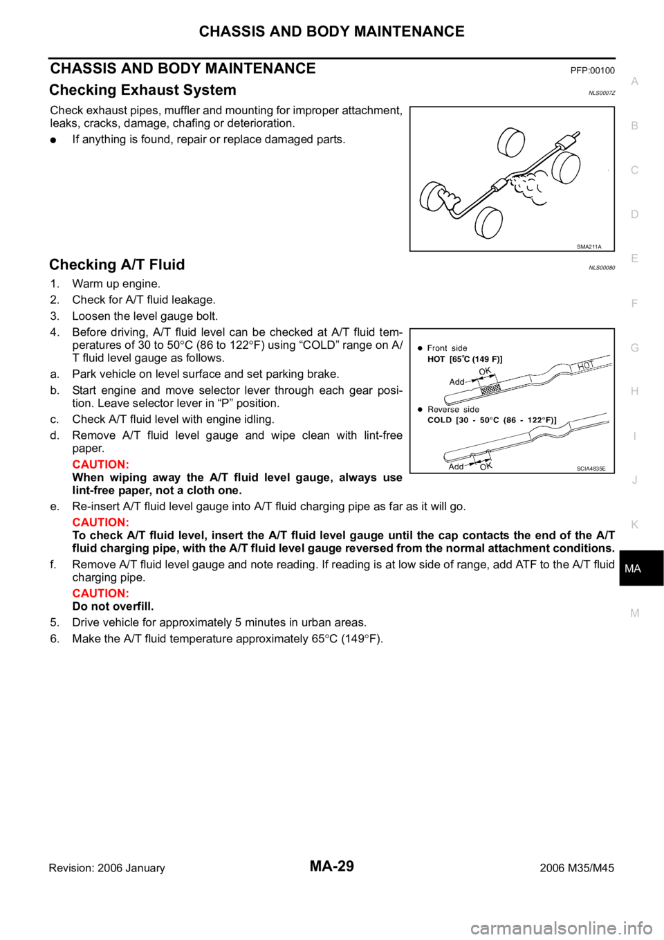
Checking Exhaust SystemNLS0007Z
Check exhaust pipes, muffler and mounting for improper attachment,
leaks, cracks, damage, chafing or deterioration.
If anything is found, repair or replace damaged parts.
Checking A/T FluidNLS00080
1. Warm up engine.
2. Check for A/T fluid leakage.
3. Loosen the level gauge bolt.
4. Before driving, A/T fluid level can be checked at A/T fluid tem-
peratures of 30 to 50
C (86 to 122F) using “COLD” range on A/
T fluid level gauge as follows.
a. Park vehicle on level surface and set parking brake.
b. Start engine and move selector lever through each gear posi-
tion. Leave selector lever in “P” position.
c. Check A/T fluid level with engine idling.
d. Remove A/T fluid level gauge and wipe clean with lint-free
paper.
CAUTION:
When wiping away the A/T fluid level gauge, always use
lint-free paper, not a cloth one.
e. Re-insert A/T fluid level gauge into A/T fluid charging pipe as far as it will go.
CAUTION:
To check A/T fluid level, insert the A/T fluid level gauge until the cap contacts the end of the A/T
fluid charging pipe, with the A/T fluid level gauge reversed from the normal attachment conditions.
f. Remove A/T fluid level gauge and note reading. If reading is at low side of range, add ATF to the A/T fluid
charging pipe.
CAUTION:
Do not overfill.
5. Drive vehicle for approximately 5 minutes in urban areas.
6. Make the A/T fluid temperature approximately 65
C (149F).
SMA211A
SCIA4835E
Page 4812 of 5621
CHASSIS AND BODY MAINTENANCE
MA-35
C
D
E
F
G
H
I
J
K
MA
B
MA
Revision: 2006 January2006 M35/M45
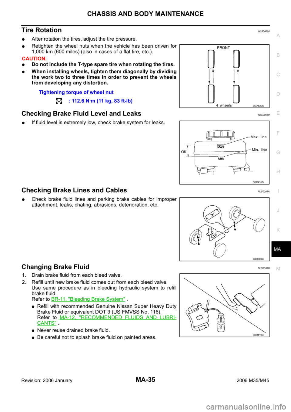
Tire RotationNLS00088
After rotation the tires, adjust the tire pressure.
Retighten the wheel nuts when the vehicle has been driven for
1,000 km (600 miles) (also in cases of a flat tire, etc.).
CAUTION:
Do not include the T-type spare tire when rotating the tires.
When installing wheels, tighten them diagonally by dividing
the work two to three times in order to prevent the wheels
from developing any distortion.
Checking Brake Fluid Level and LeaksNLS00089
If fluid level is extremely low, check brake system for leaks.
Checking Brake Lines and CablesNLS0008A
Check brake fluid lines and parking brake cables for improper
attachment, leaks, chafing, abrasions, deterioration, etc.
Changing Brake FluidNLS0008B
1. Drain brake fluid from each bleed valve.
2. Refill until new brake fluid comes out from each bleed valve.
Use same procedure as in bleeding hydraulic system to refill
brake fluid.
Refer to BR-11, "
Bleeding Brake System" .
Refill with recommended Genuine Nissan Super Heavy Duty
Brake Fluid or equivalent DOT 3 (US FMVSS No. 116).
Refer to MA-12, "
RECOMMENDED FLUIDS AND LUBRI-
CANTS" .
Never reuse drained brake fluid.
Be careful not to splash brake fluid on painted areas.Tightening torque of wheel nut
: 112.6 Nꞏm (11 kg, 83 ft-lb)
SMA829C
SBR451D
SBR389C
SBR419C
Page 4813 of 5621
MA-36
CHASSIS AND BODY MAINTENANCE
Revision: 2006 January2006 M35/M45
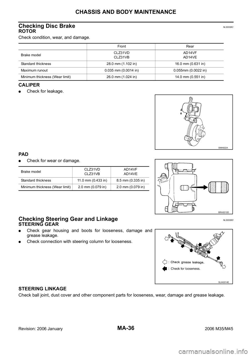
Checking Disc BrakeNLS0008C
ROTOR
Check condition, wear, and damage.
CALIPER
Check for leakage.
PA D
Check for wear or damage.
Checking Steering Gear and LinkageNLS0008D
STEERING GEAR
Check gear housing and boots for looseness, damage and
grease leakage.
Check connection with steering column for looseness.
STEERING LINKAGE
Check ball joint, dust cover and other component parts for looseness, wear, damage and grease leakage.
Front Rear
Brake modelCLZ31VD
CLZ31VBAD14VF
AD14VE
Standard thickness 28.0 mm (1.102 in) 16.0 mm (0.631 in)
Maximum runout 0.035 mm (0.0014 in) 0.055mm (0.0022 in)
Minimum thickness (Wear limit) 26.0 mm (1.024 in) 14.0 mm (0.551 in)
SMA922A
Brake modelCLZ31VD
CLZ31VBAD14VF
AD14VE
Standard thickness 11.0 mm (0.433 in) 8.5 mm (0.335 in)
Minimum thickness (Wear limit) 2.0 mm (0.079 in) 2.0 mm (0.079 in)
BRA0010D
SLIA0014E
Page 4820 of 5621

PB-1
PARKING BRAKE SYSTEM
F BRAKES
CONTENTS
C
D
E
G
H
I
J
K
L
M
SECTION PB
A
B
PB
Revision: 2006 January2006 M35/M45
PARKING BRAKE SYSTEM
PARKING BRAKE SYSTEM ...................................... 2
On-Vehicle Service ................................................... 2
PEDAL STROKE ................................................... 2
INSPECT COMPONENTS .................................... 2
ADJUSTMENT ...................................................... 2
PARKING BRAKE CONTROL ................................... 3
Components ............................................................. 3
Removal and Installation .......................................... 4
REMOVAL ........................................................
..... 4
INSTALLATION ..................................................... 4PARKING BRAKE SHOE ........................................... 5
Components ............................................................. 5
Removal and Installation .......................................... 6
REMOVAL ........................................................
..... 6
INSPECTION AFTER REMOVAL ......................... 6
INSTALLATION ..................................................... 7
SERVICE DATA AND SPECIFICATIONS (SDS) ........ 8
Parking Drum Brake ................................................. 8
Parking Brake Control .............................................. 8
Page 4821 of 5621
PB-2
PARKING BRAKE SYSTEM
Revision: 2006 January2006 M35/M45
PARKING BRAKE SYSTEMPFP:36010
On-Vehicle ServiceNFS000PR
PEDAL STROKE
Operate parking brake pedal with a force of 196 N (20 kg, 44 lb), make sure pedal stroke is within the
specified number of notches. (Check it by listening and counting ratchet clicks.)
INSPECT COMPONENTS
Make sure that the mounting conditions (looseness, backlash, etc.) of each component are normal.
Check the following:
–Device assembly for bend, damage and cracks. Replace if there are.
–Cables and equalizer for wear and damage. Replace if there are.
–Parking brake switch. Replace if it does not work correctly.
ADJUSTMENT
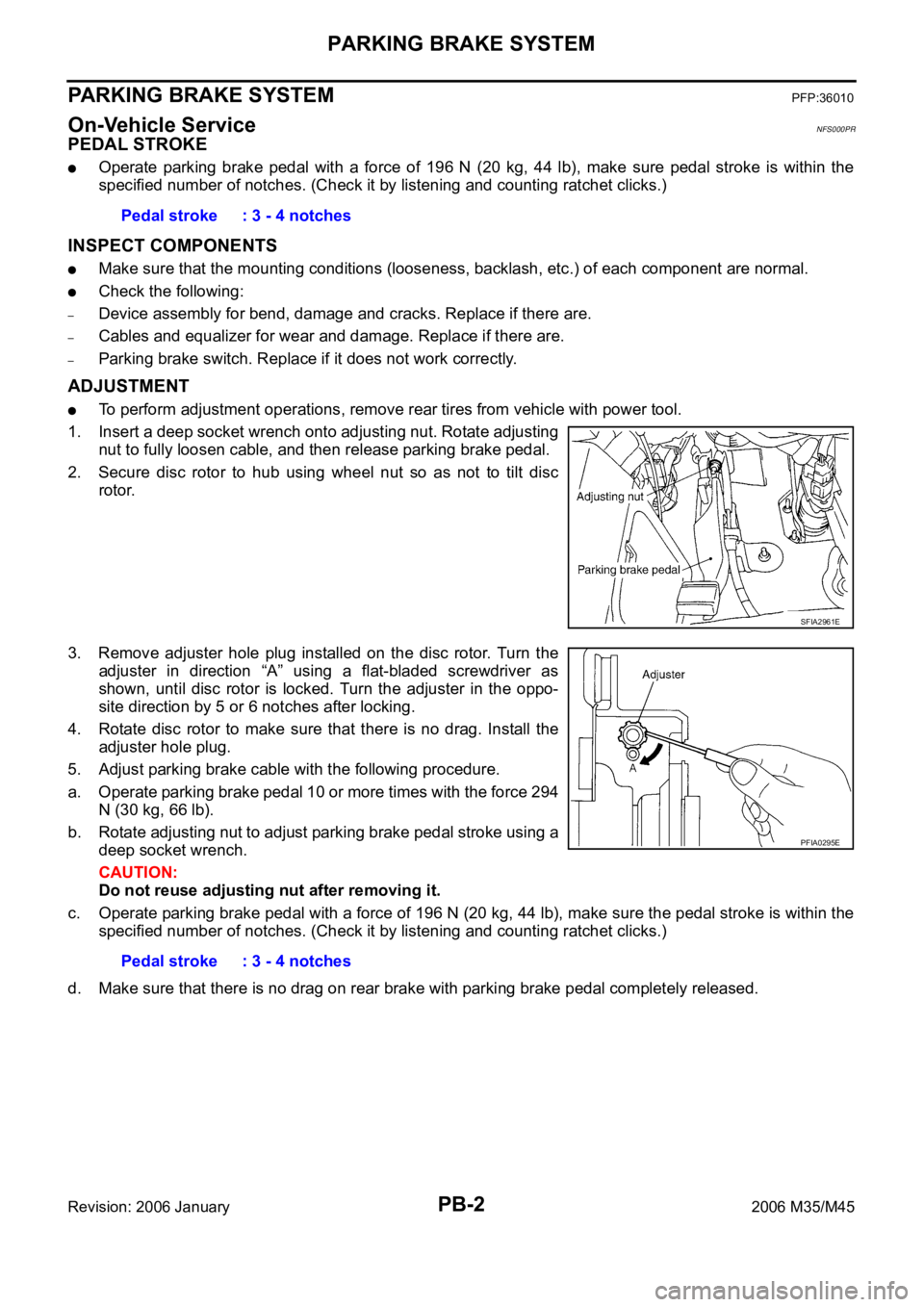
To perform adjustment operations, remove rear tires from vehicle with power tool.
1. Insert a deep socket wrench onto adjusting nut. Rotate adjusting
nut to fully loosen cable, and then release parking brake pedal.
2. Secure disc rotor to hub using wheel nut so as not to tilt disc
rotor.
3. Remove adjuster hole plug installed on the disc rotor. Turn the
adjuster in direction “A” using a flat-bladed screwdriver as
shown, until disc rotor is locked. Turn the adjuster in the oppo-
site direction by 5 or 6 notches after locking.
4. Rotate disc rotor to make sure that there is no drag. Install the
adjuster hole plug.
5. Adjust parking brake cable with the following procedure.
a. Operate parking brake pedal 10 or more times with the force 294
N (30 kg, 66 lb).
b. Rotate adjusting nut to adjust parking brake pedal stroke using a
deep socket wrench.
CAUTION:
Do not reuse adjusting nut after removing it.
c. Operate parking brake pedal with a force of 196 N (20 kg, 44 lb), make sure the pedal stroke is within the
specified number of notches. (Check it by listening and counting ratchet clicks.)
d. Make sure that there is no drag on rear brake with parking brake pedal completely released. Pedal stroke : 3 - 4 notches
SFIA2961E
Pedal stroke : 3 - 4 notches
PFIA0295E