Page 4822 of 5621
PARKING BRAKE CONTROL
PB-3
C
D
E
G
H
I
J
K
L
MA
B
PB
Revision: 2006 January2006 M35/M45
PARKING BRAKE CONTROLPFP:36010
ComponentsNFS000PS
1. Device assembly 2. Parking brake switch 3. Pedal pad
4. Adjusting nut 5. Stopper rubber 6. Return spring
7. Spring insulator 8. Front cable 9. Equalizer
10. Spring 11. Rear cable (LH) 12. Pin
13. Rear cable (RH) 14. Lock plate : Multi purpose grease
Refer to GI section for symbol marks except in the above.
SFIA2962E
Page 4823 of 5621

PB-4
PARKING BRAKE CONTROL
Revision: 2006 January2006 M35/M45
Removal and InstallationNFS000PT
REMOVAL
1. Remove rear tires from vehicle with power tool.
2. Remove instrument driver lower panel. Refer to IP-10, "
INSTRUMENT PANEL ASSEMBLY" .
3. Disconnect parking brake switch connector.
4. Remove adjusting nut and loosen front cable.
5. Remove device assembly mounting nuts and remove device assembly from vehicle.
6. Remove center console. Refer to IP-19, "
CENTER CONSOLE ASSEMBLY" .
7. Separate rear cable from front cable, remove front cable from vehicle.
8. Remove heat insulator of the exhaust center tube from vehicle.
9. Remove parking brake shoe, and remove rear cable from toggle lever. Refer to PB-6, "
Removal and
Installation" .
10. Remove rear cable mounting bolts and nuts, pull out rear cable from vehicle.
INSTALLATION
1. Install in the reverse order of the removal. Refer to PB-3, "Components" for tightening torque.
CAUTION:
Do not reuse adjusting nut.
2. Adjust parking brake. Refer to PB-2, "
ADJUSTMENT" .
Page 4824 of 5621
PARKING BRAKE SHOE
PB-5
C
D
E
G
H
I
J
K
L
MA
B
PB
Revision: 2006 January2006 M35/M45
PARKING BRAKE SHOEPFP:44060
ComponentsNFS000PU
1. Return spring 2. Adjuster 3. Brake shoe
4. Anti-rattle pin 5. Retainer 6. Anti-rattle spring
7. Toggle lever
: PBC (Poly Butyl Cuprysil) grease
or silicone-based grease
SFIA2819J
Page 4825 of 5621

PB-6
PARKING BRAKE SHOE
Revision: 2006 January2006 M35/M45
Removal and InstallationNFS000PV
REMOVAL
WAR NING :
Clean brakes with a vacuum dust collector to minimize the hazard of air borne particles or other mate-
rials.
CAUTION:
Clean dust on disc rotor and back plate using a vacuum dust collector. Do not blow with com-
pressed air.
Put matching marks on both disc rotor and wheel hub when removing disc rotor.
1. Remove rear tires from vehicle with power tool.
2. Remove disc rotor with parking brake pedal completely in the released position. Refer to BR-31,
"Removal and Installation of Brake Caliper Assembly" .
3. If disc rotor cannot be removed, remove as follows:
a. Secure the disc rotor in place with wheel nuts and remove adjuster hole plug.
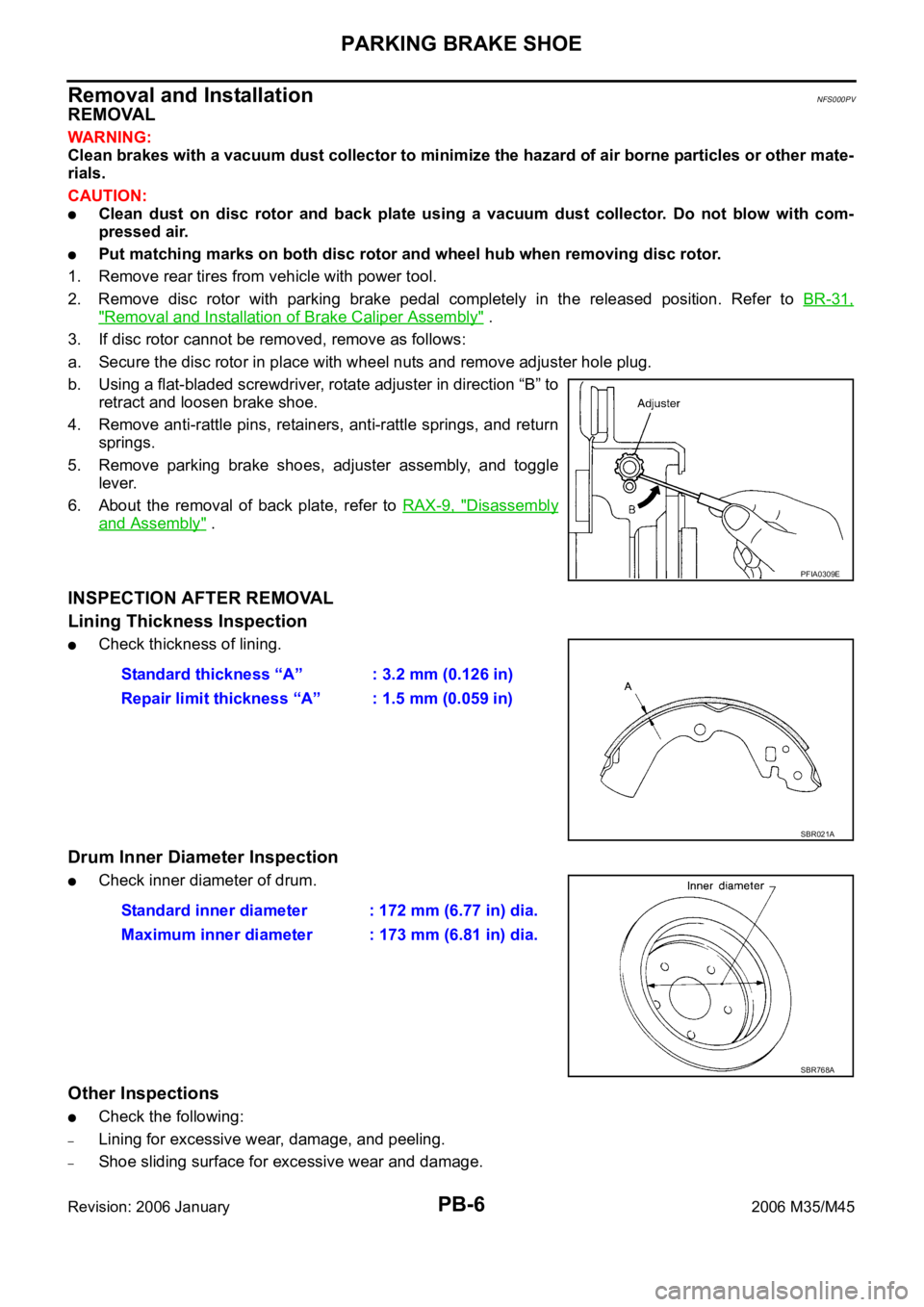
b. Using a flat-bladed screwdriver, rotate adjuster in direction “B” to
retract and loosen brake shoe.
4. Remove anti-rattle pins, retainers, anti-rattle springs, and return
springs.
5. Remove parking brake shoes, adjuster assembly, and toggle
lever.
6. About the removal of back plate, refer to RAX-9, "
Disassembly
and Assembly" .
INSPECTION AFTER REMOVAL
Lining Thickness Inspection
Check thickness of lining.
Drum Inner Diameter Inspection
Check inner diameter of drum.
Other Inspections
Check the following:
–Lining for excessive wear, damage, and peeling.
–Shoe sliding surface for excessive wear and damage.
PFIA0309E
Standard thickness “A” : 3.2 mm (0.126 in)
Repair limit thickness “A” : 1.5 mm (0.059 in)
SBR021A
Standard inner diameter : 172 mm (6.77 in) dia.
Maximum inner diameter : 173 mm (6.81 in) dia.
SBR768A
Page 4826 of 5621

PARKING BRAKE SHOE
PB-7
C
D
E
G
H
I
J
K
L
MA
B
PB
Revision: 2006 January2006 M35/M45
–Anti-rattle pin for excessive wear and corrosion.
–Return spring for sagging.
Make sure that adjuster moves smoothly.
Visually check the inside of drum for excessive wear, cracks, and damage. Check the inside of drum using
a pair of vernier calipers.
Replace with new part if the above part is malfunction.
INSTALLATION
Note the following, and install in the reverse order of removal.
Refer to PB-5, "Components" and apply PBC (Poly Butyl Cupry-
sil) grease or equivalent to the specified points during assembly.
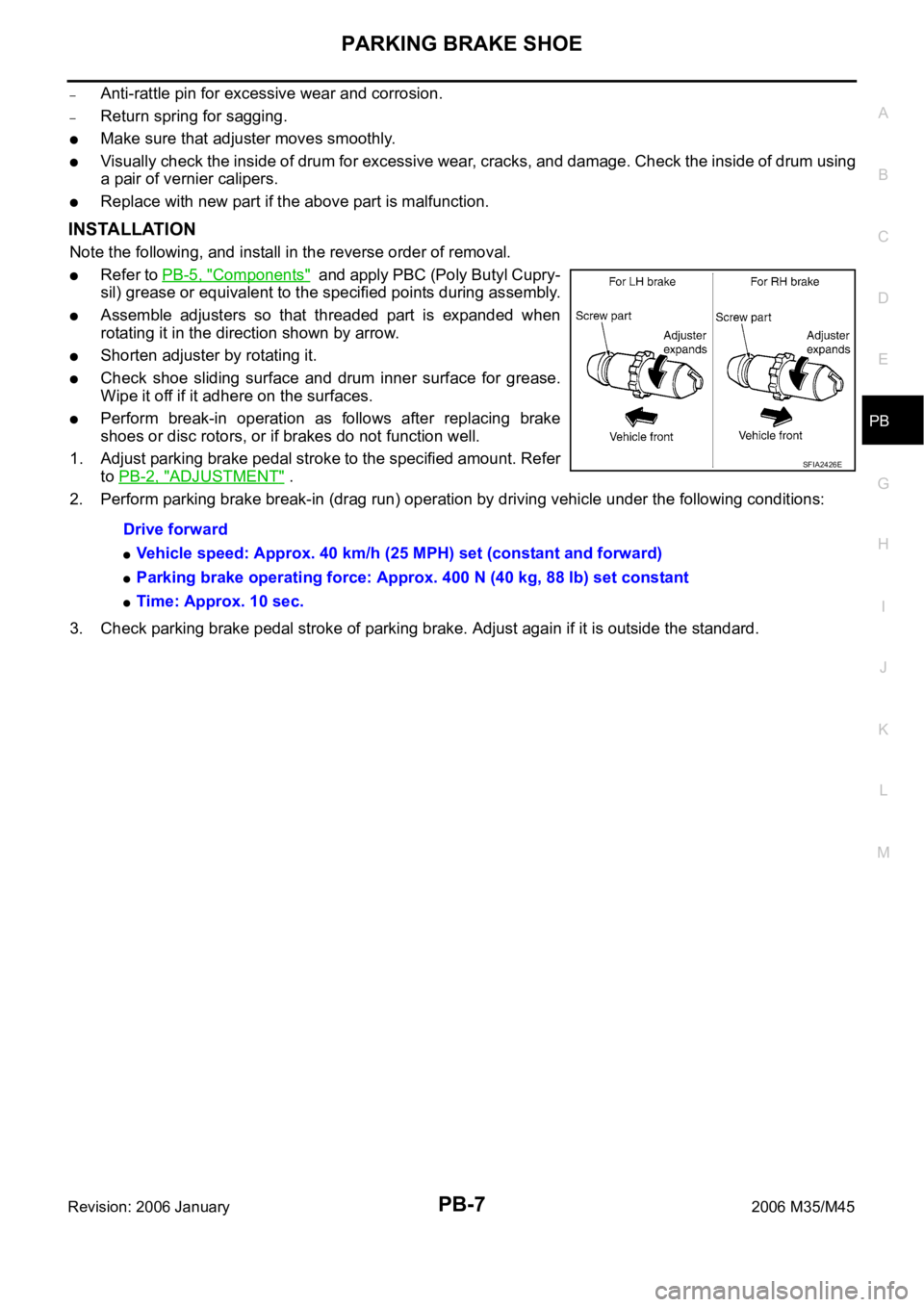
Assemble adjusters so that threaded part is expanded when
rotating it in the direction shown by arrow.
Shorten adjuster by rotating it.
Check shoe sliding surface and drum inner surface for grease.
Wipe it off if it adhere on the surfaces.
Perform break-in operation as follows after replacing brake
shoes or disc rotors, or if brakes do not function well.
1. Adjust parking brake pedal stroke to the specified amount. Refer
to PB-2, "
ADJUSTMENT" .
2. Perform parking brake break-in (drag run) operation by driving vehicle under the following conditions:
3. Check parking brake pedal stroke of parking brake. Adjust again if it is outside the standard. Drive forward
Vehicle speed: Approx. 40 km/h (25 MPH) set (constant and forward)
Parking brake operating force: Approx. 400 N (40 kg, 88 lb) set constant
Time: Approx. 10 sec.
SFIA2426E
Page 4827 of 5621
PB-8
SERVICE DATA AND SPECIFICATIONS (SDS)
Revision: 2006 January2006 M35/M45
SERVICE DATA AND SPECIFICATIONS (SDS)PFP:00030
Parking Drum Brake NFS000PW
Parking Brake ControlNFS000PX
Ty p eDS17HE
Brake liningStandard thickness 3.2 mm (0.126 in)
Repair limit thickness 1.5 mm (0.059 in)
Drum (disc)Standard inner diameter 172 mm (6.77 in) dia.
Maximum inner diameter 173 mm (6.81 in) dia.
Control typeFoot pedal
Number of notches [under force of 196 N (20 kg, 44 lb)] 3
4 notches
Number of notches when parking brake warning lamp switch comes on 1 notch
Page 4860 of 5621

PDU (POWER DISTRIBUTION UNIT)
PG-33
C
D
E
F
G
H
I
J
L
MA
B
PG
Revision: 2006 January2006 M35/M45
PDU (POWER DISTRIBUTION UNIT)PFP:285F1
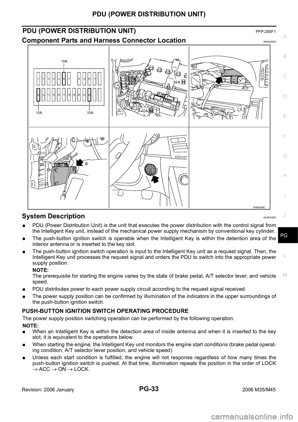
Component Parts and Harness Connector LocationNKS004ED
System DescriptionNKS004EE
PDU (Power Distribution Unit) is the unit that executes the power distribution with the control signal from
the Intelligent Key unit, instead of the mechanical power supply mechanism by conventional key cylinder.
The push-button ignition switch is operable when the Intelligent Key is within the detention area of the
interior antenna or is inserted to the key slot.
The push-button ignition switch operation is input to the Intelligent Key unit as a request signal. Then, the
Intelligent Key unit processes the request signal and orders the PDU to switch into the appropriate power
supply position.
NOTE:
The prerequisite for starting the engine varies by the state of brake pedal, A/T selector lever, and vehicle
speed.
PDU distributes power to each power supply circuit according to the request signal received.
The power supply position can be confirmed by illumination of the indicators in the upper surroundings of
the push-button ignition switch.
PUSH-BUTTON IGNITION SWITCH OPERATING PROCEDURE
The power supply position switching operation can be performed by the following operation.
NOTE:
When an Intelligent Key is within the detection area of inside antenna and when it is inserted to the key
slot, it is equivalent to the operations below.
When starting the engine, the Intelligent Key unit monitors the engine start conditions (brake pedal operat-
ing condition, A/T selector lever position, and vehicle speed).
Unless each start condition is fulfilled, the engine will not response regardless of how many times the
push-button ignition switch is pushed. At that time, illumination repeats the position in the order of LOCK
ACC ON LOCK.
PIIB6094E
Page 4861 of 5621

PG-34
PDU (POWER DISTRIBUTION UNIT)
Revision: 2006 January2006 M35/M45
*1: When the A/T selector lever position is N position, the engine start condition is different according to the vehicle speed.
At vehicle speed of 5 km/h or less, the engine can start only when the brake pedal is depressed.
At vehicle speed of 5 km/h or more, the engine can start even if the brake pedal is not depressed. (It is the same as “Engine stall
return operation while driving”.)
*2: When the A/T selector lever position is any position other than P position and when the vehicle speed is 5 km/h or more, the engine
stop condition is different.
Press and hold the push-button ignition switch for 2 seconds or more. (When the push-button ignition switch is pressed for too short
a time, the operation may be invalid, so properly press and hold to prevent the incorrect operation.)
Press the push-button ignition switch 3 times within 1.5 seconds. (Emergency stop operation) Power supply positionEngine start/stop condition Push-button ignition
switch operation fre-
quency Brake pedal operation condition A/T selector lever position
LOCK
ACCNot depressed
(When A/T selector lever is in any posi-
tion other than P or N, there will be no
effect even if it is depressed.)Any position other than P or N
(When the brake pedal is not
depressed, there will be no effect even
if the A/T selector lever is in P or N
position.)1
LOCK
ACC ONNot depressed
(When A/T selector lever is in any posi-
tion other than P or N, there will be no
effect even if it is depressed.)Any position other than P or N
(When the brake pedal is not
depressed, there will be no effect even
if the A/T selector lever is in P or N
position.)2
LOCK
ACC ON
LOCKNot depressed
(When A/T selector lever is in any posi-
tion other than P or N, there will be no
effect even if it is depressed.)Any position other than P or N
(When the brake pedal is not
depressed, there will be no effect even
if the A/T selector lever is in P or N
position.)3
LOCK
START
ACC
START
ON
START
(Engine start)Depressed P or N position (*1)1
[If the switch is
pushed once, the
engine starts from
any power supply
position (LOCK,
ACC, and ON)]
Engine start condition
LOCK
(Engine stop)— P position 1
Engine start condition
ACC
(Engine stop)— Any position other than P (*2) 1
Engine stall return
operation while driving— N position 1