2006 INFINITI M35 brake
[x] Cancel search: brakePage 3369 of 5621

FAX-10
FRONT DRIVE SHAFT
Revision: 2006 January2006 M35/M45
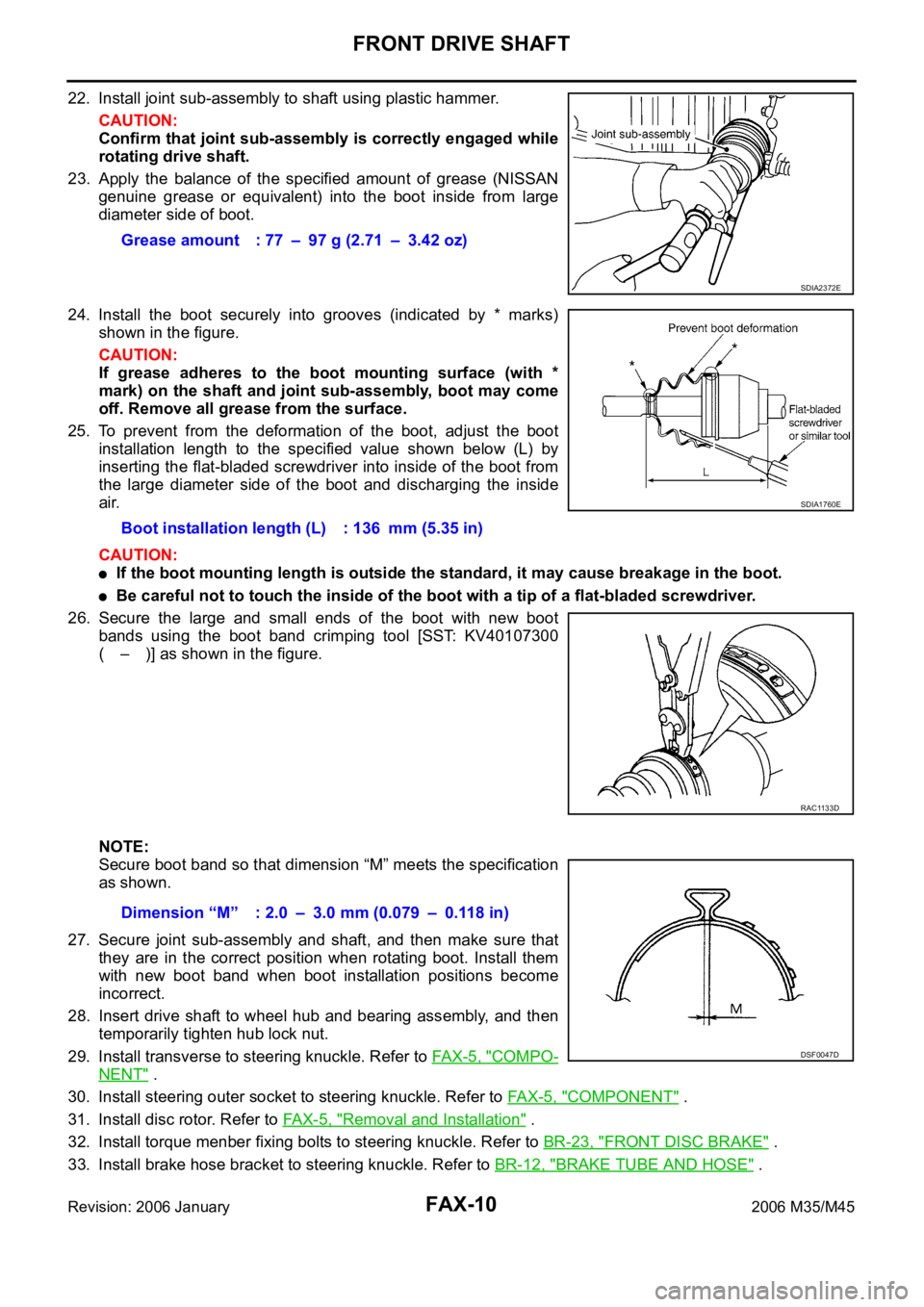
22. Install joint sub-assembly to shaft using plastic hammer.
CAUTION:
Confirm that joint sub-assembly is correctly engaged while
rotating drive shaft.
23. Apply the balance of the specified amount of grease (NISSAN
genuine grease or equivalent) into the boot inside from large
diameter side of boot.
24. Install the boot securely into grooves (indicated by * marks)
shown in the figure.
CAUTION:
If grease adheres to the boot mounting surface (with *
mark) on the shaft and joint sub-assembly, boot may come
off. Remove all grease from the surface.
25. To prevent from the deformation of the boot, adjust the boot
installation length to the specified value shown below (L) by
inserting the flat-bladed screwdriver into inside of the boot from
the large diameter side of the boot and discharging the inside
air.
CAUTION:
If the boot mounting length is outside the standard, it may cause breakage in the boot.
Be careful not to touch the inside of the boot with a tip of a flat-bladed screwdriver.
26. Secure the large and small ends of the boot with new boot
bands using the boot band crimping tool [SST: KV40107300
( – )] as shown in the figure.
NOTE:
Secure boot band so that dimension “M” meets the specification
as shown.
27. Secure joint sub-assembly and shaft, and then make sure that
they are in the correct position when rotating boot. Install them
with new boot band when boot installation positions become
incorrect.
28. Insert drive shaft to wheel hub and bearing assembly, and then
temporarily tighten hub lock nut.
29. Install transverse to steering knuckle. Refer to FAX-5, "
COMPO-
NENT" .
30. Install steering outer socket to steering knuckle. Refer to FA X - 5 , "
COMPONENT" .
31. Install disc rotor. Refer to FA X - 5 , "
Removal and Installation" .
32. Install torque menber fixing bolts to steering knuckle. Refer to BR-23, "
FRONT DISC BRAKE" .
33. Install brake hose bracket to steering knuckle. Refer to BR-12, "
BRAKE TUBE AND HOSE" . Grease amount : 77 – 97 g (2.71 – 3.42 oz)
SDIA2372E
Boot installation length (L) : 136 mm (5.35 in)
SDIA1760E
RAC1133D
Dimension “M” : 2.0 – 3.0 mm (0.079 – 0.118 in)
DSF0047D
Page 3370 of 5621

FRONT DRIVE SHAFT
FAX-11
C
E
F
G
H
I
J
K
L
MA
B
FA X
Revision: 2006 January2006 M35/M45
34. Install wheel sensor to steering knuckle. Refer to BRC-57, "WHEEL SENSOR" .
35. Tighten the hub lock nut to the specified torque. Refer to FA X - 5 , "
COMPONENT" .
36. Install cotter pin.
37. Install tires to vehicle.
Removal and InstallationNDS000FI
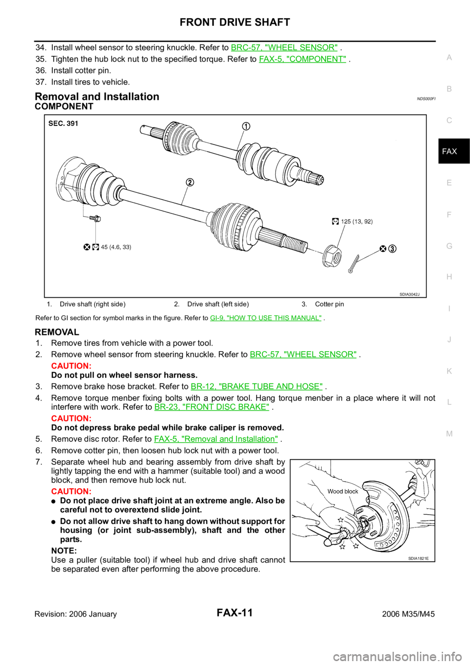
COMPONENT
Refer to GI section for symbol marks in the figure. Refer to GI-9, "HOW TO USE THIS MANUAL" .
REMOVAL
1. Remove tires from vehicle with a power tool.
2. Remove wheel sensor from steering knuckle. Refer to BRC-57, "
WHEEL SENSOR" .
CAUTION:
Do not pull on wheel sensor harness.
3. Remove brake hose bracket. Refer to BR-12, "
BRAKE TUBE AND HOSE" .
4. Remove torque menber fixing bolts with a power tool. Hang torque menber in a place where it will not
interfere with work. Refer to BR-23, "
FRONT DISC BRAKE" .
CAUTION:
Do not depress brake pedal while brake caliper is removed.
5. Remove disc rotor. Refer to FAX-5, "
Removal and Installation" .
6. Remove cotter pin, then loosen hub lock nut with a power tool.
7. Separate wheel hub and bearing assembly from drive shaft by
lightly tapping the end with a hammer (suitable tool) and a wood
block, and then remove hub lock nut.
CAUTION:
Do not place drive shaft joint at an extreme angle. Also be
careful not to overextend slide joint.
Do not allow drive shaft to hang down without support for
housing (or joint sub-assembly), shaft and the other
parts.
NOTE:
Use a puller (suitable tool) if wheel hub and drive shaft cannot
be separated even after performing the above procedure.
1. Drive shaft (right side) 2. Drive shaft (left side) 3. Cotter pin
SDIA3042J
SDIA1821E
Page 3379 of 5621

FFD-2
PRECAUTIONS
Revision: 2006 January2006 M35/M45
PRECAUTIONSPFP:00001
Precautions Necessary for Steering Wheel Rotation after Battery DisconnectNDS000EK
NOTE:
Before removing and installing any control units, first turn the push-button ignition switch to the LOCK
position, then disconnect both battery cables.
After finishing work, confirm that all control unit connectors are connected properly, then re-connect both
battery cables.
Always use CONSULT-II to perform self-diagnosis as a part of each function inspection after finishing
work. If a DTC is detected, perform trouble diagnosis according to self-diagnosis results.
This vehicle is equipped with a push-button ignition switch and a steering lock unit.
If the battery is disconnected or discharged, the steering wheel will lock and cannot be turned.
If turning the steering wheel is required with the battery disconnected or discharged, follow the procedure
below before starting the repair operation.
OPERATION PROCEDURE
1. Connect both battery cables.
NOTE:
Supply power using jumper cables if battery is discharged.
2. Carry the Intelligent Key or insert it to the key slot and turn the push-button ignition switch to ACC position.
(At this time, the steering lock will be released.)
3. Disconnect both battery cables. The steering lock will remain released with both battery cables discon-
nected and the steering wheel can be turned.
4. Perform the necessary repair operation.
5. When the repair work is completed, re-connect both battery cables. With the brake pedal released, turn
the push-button ignition switch from ACC position to ON position, then to LOCK position. (The steering
wheel will lock when the push-button ignition switch is turned to LOCK position.)
6. Perform self-diagnosis check of all control units using CONSULT-II.
Service Notice or PrecautionsNDS000EL
Check for the correct installation status prior to removal or disassembly. If matching marks are required,
be certain they do not interfere with the function of the parts when applied.
Overhaul should be done in a clean work area, it is preferable to work in dustproof area.
Before disassembly, using steam or white gasoline, completely remove sand and mud from the exterior of
the unit, preventing them from entering into the unit during disassembly or assembly.
Check appearance of the disassembled parts for damage, deformation, and unusual wear. Replace them
with a new ones if necessary.
Gaskets, seals and O-rings should be replaced any time when the unit is disassembled.
In principle, tighten bolts or nuts gradually in several steps working diagonally from inside to outside. If
tightening sequence is specified, observe it.
Clean and flush the parts sufficiently and blow-dry them.
Be careful not to damage sliding surfaces and mating surfaces.
When applying sealant, remove the old sealant from the mounting surface; then remove any moisture, oil,
and foreign materials from the application and mounting surfaces.
Always use shop paper for cleaning the inside of components.
Avoid using cotton gloves or shop rags to prevent entering of lint.
During assembly, observe the specified tightening torque, and apply new gear oil, petroleum jelly, or multi-
purpose grease as specified for each vehicle, if necessary.
Page 3383 of 5621

FFD-6
NOISE, VIBRATION AND HARSHNESS (NVH) TROUBLESHOOTING
Revision: 2006 January2006 M35/M45
NOISE, VIBRATION AND HARSHNESS (NVH) TROUBLESHOOTINGPFP:00003
NVH Troubleshooting ChartNDS000EO
Use the chart below to help you find the cause of the symptom. If necessary, repair or replace these parts.
: ApplicableReference page
Refer to FFD-24, "
INSPECTION AFTER DISASSEMBLY
" .
Refer to FFD-17, "
Tooth Contact
" .
Refer to FFD-24, "
INSPECTION AFTER DISASSEMBLY
" .
Refer to FFD-19, "
Backlash
" .
Refer to FFD-19, "
Companion Flange Runout
" .
Refer to FFD-8, "
Checking Differential Gear Oil
" .
NVH in PR section.
NVH in FAX, RAX, FSU and RSU sections.
NVH in WT section.
NVH in WT section.
NVH in FAX and RAX section.
NVH in BR section.
NVH in PS section.
Possible cause and SUSPECTED PARTS
Gear tooth rough
Gear contact improper
Tooth surfaces worn
Backlash incorrect
Companion flange excessive runout
Gear oil improper
PROPELLER SHAFT
AXLE AND SUSPENSION
TIRES
ROAD WHEEL
DRIVE SHAFT
BRAKES
STEERING
Symptom Noise
Page 3423 of 5621

FL-10
FUEL TANK
Revision: 2006 January2006 M35/M45
FUEL TANKPFP:17202
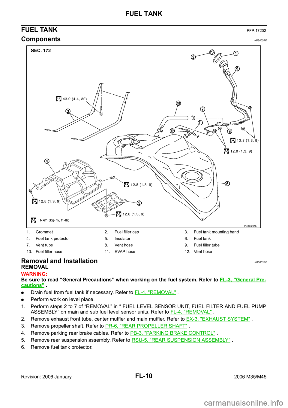
ComponentsNBS005RE
Removal and InstallationNBS005RF
REMOVAL
WAR NING :
Be sure to read “General Precautions” when working on the fuel system. Refer to FL-3, "
General Pre-
cautions" .
Drain fuel from fuel tank if necessary. Refer to FL-4, "REMOVAL" .
Perform work on level place.
1. Perform steps 2 to 7 of “REMOVAL” in “ FUEL LEVEL SENSOR UNIT, FUEL FILTER AND FUEL PUMP
ASSEMBLY” on main and sub fuel level sensor units. Refer to FL-4, "
REMOVAL" .
2. Remove exhaust front tube, center muffler and main muffler. Refer to EX-3, "
EXHAUST SYSTEM" .
3. Remove propeller shaft. Refer to PR-6, "
REAR PROPELLER SHAFT" .
4. Remove parking rear brake cables. Refer to PB-3, "
PARKING BRAKE CONTROL" .
5. Remove rear suspension assembly. Refer to RSU-5, "
REAR SUSPENSION ASSEMBLY" .
6. Remove fuel tank protector.
1. Grommet 2. Fuel filler cap 3. Fuel tank mounting band
4. Fuel tank protector 5. Insulator 6. Fuel tank
7. Vent tube 8. Vent hose 9. Fuel filler tube
10. Fuel filler hose 11. EVAP hose 12. Vent hose
PBIC3201E
Page 3432 of 5621
![INFINITI M35 2006 Factory Service Manual NOISE, VIBRATION AND HARSHNESS (NVH) TROUBLESHOOTING
FSU-5
[2WD]
C
D
F
G
H
I
J
K
L
MA
B
FSU
Revision: 2006 January2006 M35/M45
NOISE, VIBRATION AND HARSHNESS (NVH) TROUBLESHOOTINGPFP:00003
NVH Trouble INFINITI M35 2006 Factory Service Manual NOISE, VIBRATION AND HARSHNESS (NVH) TROUBLESHOOTING
FSU-5
[2WD]
C
D
F
G
H
I
J
K
L
MA
B
FSU
Revision: 2006 January2006 M35/M45
NOISE, VIBRATION AND HARSHNESS (NVH) TROUBLESHOOTINGPFP:00003
NVH Trouble](/manual-img/42/57023/w960_57023-3431.png)
NOISE, VIBRATION AND HARSHNESS (NVH) TROUBLESHOOTING
FSU-5
[2WD]
C
D
F
G
H
I
J
K
L
MA
B
FSU
Revision: 2006 January2006 M35/M45
NOISE, VIBRATION AND HARSHNESS (NVH) TROUBLESHOOTINGPFP:00003
NVH Troubleshooting ChartNES000I9
Use chart below to help you find the cause of the symptom. If necessary, repair or replace these parts.
: ApplicableReference page
FSU-8FSU-12
—
—
—
FSU-8FSU-6FSU-18
NVH in PR section
NVH in FAX and FSU section
NVH in WT section
NVH in BR section
NVH in PS section
Possible cause and SUSPECTED PARTS
Improper installation, looseness
Strut deformation, damage or deflection
Bushing or mounting deterioration
Parts interference
Spring fatigue
Suspension looseness
Incorrect wheel alignment
Stabilizer bar fatigue
PROPELLER SHAFT
FRONT AXLE AND FRONT SUSPENSION
ROAD WHEEL
BRAKES
STEERING
Symptom FRONT SUSPENSIONNoise
Shake
Vibration
Shimmy
Judder
Poor quality ride or han-
dling
Page 3433 of 5621
![INFINITI M35 2006 Factory Service Manual FSU-6
[2WD]
FRONT SUSPENSION ASSEMBLY
Revision: 2006 January2006 M35/M45
FRONT SUSPENSION ASSEMBLYPFP:54010
On-Vehicle Inspection and ServiceNES000IA
Make sure the mounting conditions (looseness, INFINITI M35 2006 Factory Service Manual FSU-6
[2WD]
FRONT SUSPENSION ASSEMBLY
Revision: 2006 January2006 M35/M45
FRONT SUSPENSION ASSEMBLYPFP:54010
On-Vehicle Inspection and ServiceNES000IA
Make sure the mounting conditions (looseness,](/manual-img/42/57023/w960_57023-3432.png)
FSU-6
[2WD]
FRONT SUSPENSION ASSEMBLY
Revision: 2006 January2006 M35/M45
FRONT SUSPENSION ASSEMBLYPFP:54010
On-Vehicle Inspection and ServiceNES000IA
Make sure the mounting conditions (looseness, back lash) of each component and component conditions
(wear, damage) are normal.
INSPECTION OF LOWER BALL JOINT END PLAY
1. Set front wheels in a straight-ahead position. Do not depress brake pedal.
2. Place an iron bar or similar tool between transverse link and steering knuckle.
3. Measure axial end play by prying it up and down.
CAUTION:
Be careful not to damage ball joint boot. Do not damage the installation position by applying
excessive force.
SHOCK ABSORBER INSPECTION
Check for oil leakage, damage and breakage of installation positions.
Wheel Alignment InspectionNES000IB
DESCRIPTION
Measure wheel alignment under unladen conditions.
NOTE:
“Unladen conditions” means that fuel, engine coolant, and lubricant are full. Spare tire, jack, hand tools and
mats are in designated positions.
PRELIMINARY CHECK
Check the following:
1. Tires for improper air pressure and wear.
2. Road wheels for runout. Refer to WT-6, "
ROAD WHEEL" .
3. Wheel bearing axial end play. Refer to FAX-5, "
WHEEL BEARING INSPECTION" .
4. Transverse link ball joint axial end play. Refer to FSU-14, "
INSPECTION AFTER REMOVAL" .
5. Shock absorber operation.
6. Each mounting part of axle and suspension for looseness and deformation.
7. Each of suspension member, shock absorber, upper link and transverse link for cracks, deformation and
other damage.
8. Vehicle height (posture).
GENERAL INFORMATION AND RECOMMENDATIONS
A four-wheel thrust alignment should be performed.
–This type of alignment is recommended for any NISSAN/INFINITI vehicle.
–The four-wheel “thrust” process helps ensure that the vehicle is properly aligned and the steering wheel is
centered.
–The alignment rack itself should be capable of accepting any NISSAN/INFINITI vehicle.
–The rack should be checked to ensure that it is level.
Make sure the machine is properly calibrated.
–Your alignment equipment should be regularly calibrated in order to give correct information.
–Check with the manufacturer of your specific equipment for their recommended Service/Calibration
Schedule.Axial end play : 0 mm (0 in)
Page 3436 of 5621
![INFINITI M35 2006 Factory Service Manual FRONT SUSPENSION ASSEMBLY
FSU-9
[2WD]
C
D
F
G
H
I
J
K
L
MA
B
FSU
Revision: 2006 January2006 M35/M45
Refer to GI section for symbol marks in the figure. Refer to GI-9, "HOW TO USE THIS MANUAL" INFINITI M35 2006 Factory Service Manual FRONT SUSPENSION ASSEMBLY
FSU-9
[2WD]
C
D
F
G
H
I
J
K
L
MA
B
FSU
Revision: 2006 January2006 M35/M45
Refer to GI section for symbol marks in the figure. Refer to GI-9, "HOW TO USE THIS MANUAL"](/manual-img/42/57023/w960_57023-3435.png)
FRONT SUSPENSION ASSEMBLY
FSU-9
[2WD]
C
D
F
G
H
I
J
K
L
MA
B
FSU
Revision: 2006 January2006 M35/M45
Refer to GI section for symbol marks in the figure. Refer to GI-9, "HOW TO USE THIS MANUAL" .
Removal and Installation NES000ID
REMOVAL
1. For VK45DE engine models, disconnect related electric wires and hoses from engine assembly to remove
front suspension member with engine assembly. Refer to EM-244, "
ENGINE ASSEMBLY" .
2. Remove cowl top panel and hood. Refer to EI-18, "
COWL TOP" , EI-17, "HOOD" .
3. For VQ35DE engine models, install engine slinger, and then hoist engine. Refer to EM-113, "
Removal and
Installation (2WD Models)" .
4. Remove tires from vehicle with a power tool.
5. Remove wheel sensor from steering knuckle. Refer to BRC-57, "
WHEEL SENSOR" .
CAUTION:
Do not pull on wheel sensor harness.
6. Remove brake hose bracket. Refer to BR-12, "
BRAKE TUBE AND HOSE" .
7. Remove undercover with a power tool.
8. Remove cotter pin (1), and then loosen the nut.
9. Remove steering outer socket (2) from steering knuckle (3) so
as not to damage ball joint boot (4) using the ball joint remover
(suitable tool).
CAUTION:
Temporarily tighten the nut to prevent damage to threads
and to prevent the ball joint remover (suitable tool) from
suddenly coming off.
10. Remove the mounting nut on the upper side of stabilizer con-
necting rod with a power tool, and then remove stabilizer con-
necting rod from transverse link.
11. Separate steering gear assembly and lower joint. Refer to PS-13, "
STEERING COLUMN" .
12. Remove rack stay. Refer to FSU-8, "
Components" .
13. Remove steering hydraulic piping bracket from front suspension member. Refer to PS-38, "
HYDRAULIC
LINE" .
14. Remove the mounting nut and bolt on the lower side of shock absorber with a power tool, and then
remove shock absorber from transverse link.
15. Remove cotter pin of transverse link and steering knuckle, and then loosen nut.
16. Set jack under front suspension member.
17. Remove transverse link from steering knuckle so as not to damage ball joint boot using the ball joint
remover (suitable tool)
CAUTION:
Temporarily tighten the nut to prevent damage to threads and to prevent ball joint remover (suit-
able tool) from suddenly coming off.
18. Remove the mounting nuts of engine mounting insulator. Refer to EM-113, "
ENGINE ASSEMBLY" .
19. Remove the mounting bolts of member bracket, and then remove member bracket from front suspension
member with a power tool. Refer to FSU-8, "
Components" .
20. Remove the mounting nut and bolts of member stay, and then remove member stay from front suspension
member and vehicle with a power tool.
21. Remove the mounting nut of front suspension member with a power tool. Refer to FSU-8, "
Components" .
22. For VQ35DE engine models, gradually lower a jack to remove front suspension assembly from vehicle.
1. Shock absorber mounting bracket 2. Bound bumper 3. Rubber seat
4. Coil spring 5. Shock absorber 6. Upper link
7. Steering knuckle 8. Transverse link 9. Washer
10. Steering stopper bracket 11. Stabilizer connecting rod 12. Stabilizer bar
13. Stabilizer bushing 14. Stabilizer clamp 15. Front suspension member
16. Rack stay 17. Member stay 18. Member bracket
19. Clamp 20. Cotter pin 21. Stopper rubber
SGIA1183E