Page 515 of 5621

ATC-68
TROUBLE DIAGNOSIS
Revision: 2006 January2006 M35/M45
1. CHECK POWER SUPPLY CIRCUIT FOR UNIFIED METER AND A/C AMP.
1. Disconnect unified meter and A/C amp. connector.
2. Check voltage between unified meter and A/C amp. harness
connector M65 terminals 41, 53 and 55 and ground.
OK or NG
OK >> GO TO 2.
NG >> Check 10A fuses [Nos. 6, 12 and 19, located in the fuse block (J/B)]. Refer to P G - 111 , "
FUSE
BLOCK - JUNCTION BOX (J/B)" .
If fuses are OK, check harness for open circuit. Repair or replace if necessary.
If fuses are NG, check harness for short circuit and replace fuse.
2. CHECK GROUND CIRCUIT FOR UNIFIED METER AND A/C AMP.
1. Turn ignition switch OFF.
2. Check continuity between unified meter and A/C amp. harness
connector M65 terminal 55, 71 and ground.
OK or NG
OK >> Replace unified meter and A/C amp.
NG >> Repair harness or connector.
Terminals Ignition switch position
(+)
(-) OFF ACC ON Unified
meter and
A/C amp.
connectorTerminal
No.
M65 41
GroundApprox. 0 VBattery
voltageBattery
voltage
M65 53 Approx. 0 V Approx. 0 VBattery
voltage
M65 54Battery
voltageBattery
voltageBattery
voltage
RJIA4050E
55, 71 – Ground : Continuity should exist.
RJIA4051E
Page 539 of 5621

ATC-92
TROUBLE DIAGNOSIS
Revision: 2006 January2006 M35/M45
1. CHECK POWER SUPPLY FOR BLOWER MOTOR
1. Disconnect blower motor connector.
2. Turn ignition switch ON.
3. Check voltage between blower motor harness connector M91
terminal 1 and ground.
OK or NG
OK >> GO TO 2.
NG >> Check power supply circuit and 15A fuses [Nos. 10 and
11, located in the fuse block (J/B)]. Refer to P G - 111 ,
"FUSE BLOCK - JUNCTION BOX (J/B)" .
If fuses are OK, check harness for open circuit. Repair or replace if necessary.
If fuses are NG, check harness for short circuit and replace fuse.
2. CHECK BLOWER MOTOR GROUND CIRCUIT
1. Turn ignition switch OFF.
2. Check continuity between blower motor harness connector M91
terminal 3 and ground.
OK or NG
OK >> GO TO 3.
NG >> Repair harness or connector.
3. CHECK CIRCUIT CONTINUITY BETWEEN BLOWER MOTOR AND UNIFIED METER AND A/C AMP.
1. Disconnect unified meter and A/C amp. connector.
2. Check continuity between blower motor harness connector M91
terminal 2 and unified meter and A/C amp. harness connector
M64 terminal 38.
OK or NG
OK >> GO TO 4.
NG >> Repair harness or connector.1 – Ground : Battery voltage
RJIA1997E
3 – Ground : Continuity should exist.
RJIA4072E
2 – 38 : Continuity should exist.
RJIA4073E
Page 937 of 5621

BCS-16
BCM (BODY CONTROL MODULE)
Revision: 2006 January2006 M35/M45
Check BCM Power Supply and Ground CircuitNKS003XM
1. CHECK FUSES
Check for blown fuses.
Refer to LT-13, "Wiring Diagram — H/LAMP —" .
OK or NG
OK >> GO TO 2.
NG >> If fuse or fusible link is blown, be sure to eliminate cause of malfunction before installing new fuse
or fusible link. Refer to PG-3, "
POWER SUPPLY ROUTING CIRCUIT" .
2. CHECK POWER SUPPLY CIRCUIT
1. Turn ignition switch OFF.
2. Disconnect BCM connector.
3. Check voltage between BCM harness connector and ground.
OK or NG
OK >> GO TO 3.
NG >> Check harness for open or short between BCM and
fuse.
3. CHECK GROUND CIRCUIT
Check continuity between BCM harness connector and ground.
OK or NG
OK >> INSPECTION END
NG >> Check harness ground circuit.
Unit Power source Fuse and fusible link No.
BCMBatteryF
18
Ignition switch ON or START position 1
Ignition switch ACC or ON position 6
Terminal Ignition switch position
(+)
(-) OFF ACC ON
BCM
ConnectorTerminal
M111
GroundApprox. 0VBattery
voltageBattery
voltage
38 Approx. 0V Approx. 0VBattery
voltage
M242 Battery
voltageBattery
voltageBattery
voltage
55 Battery
voltageBattery
voltageBattery
voltage
PKIA5204E
Terminal Continuity
BCM
ConnectorTerminal
Ground Yes
M2 52
SKIB5125E
Page 1452 of 5621

COMBINATION METERS
DI-19
C
D
E
F
G
H
I
J
L
MA
B
DI
Revision: 2006 January2006 M35/M45
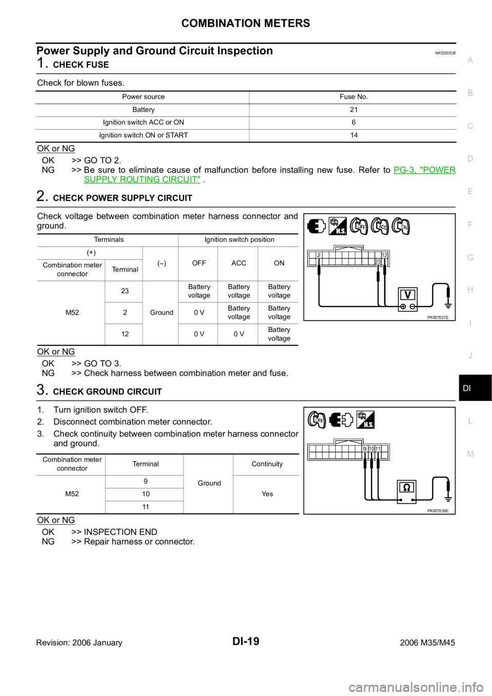
Power Supply and Ground Circuit InspectionNKS003U6
1. CHECK FUSE
Check for blown fuses.
OK or NG
OK >> GO TO 2.
NG >> Be sure to eliminate cause of malfunction before installing new fuse. Refer to PG-3, "
POWER
SUPPLY ROUTING CIRCUIT" .
2. CHECK POWER SUPPLY CIRCUIT
Check voltage between combination meter harness connector and
ground.
OK or NG
OK >> GO TO 3.
NG >> Check harness between combination meter and fuse.
3. CHECK GROUND CIRCUIT
1. Turn ignition switch OFF.
2. Disconnect combination meter connector.
3. Check continuity between combination meter harness connector
and ground.
OK or NG
OK >> INSPECTION END
NG >> Repair harness or connector.
Power source Fuse No.
Battery 21
Ignition switch ACC or ON 6
Ignition switch ON or START 14
Terminals Ignition switch position
(+)
(–) OFF ACC ON
Combination meter
connectorTerminal
M5223
GroundBattery
voltageBattery
voltageBattery
voltage
20 VBattery
voltageBattery
voltage
12 0 V 0 VBattery
voltage
PKIB7637E
Combination meter
connectorTerminal
GroundContinuity
M529
Ye s 10
11
PKIB7638E
Page 1468 of 5621

UNIFIED METER AND A/C AMP
DI-35
C
D
E
F
G
H
I
J
L
MA
B
DI
Revision: 2006 January2006 M35/M45
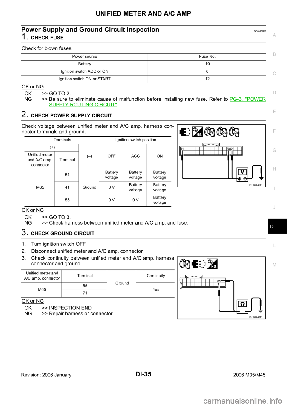
Power Supply and Ground Circuit InspectionNKS003UJ
1. CHECK FUSE
Check for blown fuses.
OK or NG
OK >> GO TO 2.
NG >> Be sure to eliminate cause of malfunction before installing new fuse. Refer to PG-3, "
POWER
SUPPLY ROUTING CIRCUIT" .
2. CHECK POWER SUPPLY CIRCUIT
Check voltage between unified meter and A/C amp. harness con-
nector terminals and ground.
OK or NG
OK >> GO TO 3.
NG >> Check harness between unified meter and A/C amp. and fuse.
3. CHECK GROUND CIRCUIT
1. Turn ignition switch OFF.
2. Disconnect unified meter and A/C amp. connector.
3. Check continuity between unified meter and A/C amp. harness
connector and ground.
OK or NG
OK >> INSPECTION END
NG >> Repair harness or connector.
Power source Fuse No.
Battery 19
Ignition switch ACC or ON 6
Ignition switch ON or START 12
Terminals Ignition switch position
(+)
(–) OFF ACC ON Unified meter
a n d A / C a m p .
connectorTerminal
M6554
GroundBattery
voltageBattery
voltageBattery
voltage
41 0 VBattery
voltageBattery
voltage
53 0 V 0 VBattery
voltage
PKIB7645E
Unified meter and
A/C amp. connectorTerminal
GroundContinuity
M6555
Ye s
71
PKIB7646E
Page 1627 of 5621
EC-84
[VQ35DE]
BASIC SERVICE PROCEDURE
Revision: 2006 January2006 M35/M45
Idle Mixture Ratio AdjustmentNBS004SS
PREPARATION
1. Make sure that the following parts are in good order.
Battery
Ignition system
Engine oil and coolant levels
Fuses
ECM harness connector
Vacuum hoses
Air intake system
(Oil filler cap, oil level gauge, etc.)
Fuel pressure
Engine compression
Throttle valve
Evaporative emission system
2. On air conditioner equipped models, checks should be carried out while the air conditioner is OFF.
3. Checks should be carried out while selector lever is in P or N position.
4. When measuring CO percentage, insert probe more than 40 cm (15.7 in) into tail pipe.
5. Turn off headlamp, heater blower, rear window defogger.
6. Keep front wheels pointed straight ahead.
Page 2338 of 5621
BASIC SERVICE PROCEDURE
EC-795
[VK45DE]
C
D
E
F
G
H
I
J
K
L
MA
EC
Revision: 2006 January2006 M35/M45
Idle Mixture Ratio AdjustmentNBS005A8
PREPARATION
1. Make sure that the following parts are in good order.
Battery
Ignition system
Engine oil and coolant levels
Fuses
ECM harness connector
Va c u u m h o s e s
Air intake system
(Oil filler cap, oil level gauge, etc.)
Fuel pressure
Engine compression
Throttle valve
Evaporative emission system
2. On air conditioner equipped models, checks should be carried out while the air conditioner is OFF.
3. Checks should be carried out while selector lever is in P or N position.
4. When measuring CO percentage, insert probe more than 40 cm (15.7 in) into tail pipe.
5. Turn off headlamp, heater blower, rear window defogger.
6. Keep front wheels pointed straight ahead.
Page 4447 of 5621

LT-20
HEADLAMP (FOR USA) - CONVENTIONAL TYPE -
Revision: 2006 January2006 M35/M45
Terminals and Reference Values for IPDM E/RNKS003O5
How to Perform Trouble DiagnosesNKS003O6
1. Confirm the symptom or customer complaint.
2. Understand operation description and function description. Refer to LT- 8 , "
System Description" .
3. Perform the Preliminary Check. Refer to LT- 2 0 , "
Preliminary Check" .
4. Check symptom and repair or replace the cause of malfunction.
5. Does the headlamp operate normally? If YES, GO TO 6. If NO, GO TO 4.
6. INSPECTION END
Preliminary CheckNKS003O7
CHECK POWER SUPPLY AND GROUND CIRCUIT
1. CHECK FUSE
Check for blown fuses.
Refer to LT-13, "Wiring Diagram — H/LAMP —" .
OK or NG
OK >> GO TO 2.
NG >> If fuse or fusible link is blown, be sure to eliminate cause of malfunction before installing new fuse
or fusible link. Refer to PG-3, "
POWER SUPPLY ROUTING CIRCUIT" .
Terminal
No.Wire
colorSignal nameMeasuring condition
Reference value
Ignition
switchOperation or condition
20 R Headlamp low (RH) ONLighting switch 2ND
positionOFF Approx. 0V
ON Battery voltage
27 BR Headlamp high (RH) ONLighting switch HIGH or
PASSING positionOFF Approx. 0V
ON Battery voltage
28 R/Y Headlamp high (LH) ONLighting switch HIGH or
PASSING positionOFF Approx. 0V
ON Battery voltage
30 R/B Headlamp low (LH) ONLighting switch 2ND
positionOFF Approx. 0V
ON Battery voltage
38 B Ground ON — Approx. 0V
49 L CAN
H — — —
50 P CAN
L — — —
51 B Ground ON — Approx. 0V
Unit Power source Fuse and fusible link No.
BCMBatteryF
21
Ignition switch ON or START position 1
Ignition switch ACC or ON position 6
IPDM E/R Battery71
72
74
76
78
86