2006 INFINITI M35 night vision
[x] Cancel search: night visionPage 743 of 5621
![INFINITI M35 2006 Factory Service Manual AV-122
[WITHOUT MOBILE ENTERTAINMENT SYSTEM]
TROUBLE DIAGNOSIS
Revision: 2006 January2006 M35/M45
Example of Symptoms Judged Not MalfunctionNKS0049E
BASIC OPERATION
NOTE:
Locations stored in the Addr INFINITI M35 2006 Factory Service Manual AV-122
[WITHOUT MOBILE ENTERTAINMENT SYSTEM]
TROUBLE DIAGNOSIS
Revision: 2006 January2006 M35/M45
Example of Symptoms Judged Not MalfunctionNKS0049E
BASIC OPERATION
NOTE:
Locations stored in the Addr](/manual-img/42/57023/w960_57023-742.png)
AV-122
[WITHOUT MOBILE ENTERTAINMENT SYSTEM]
TROUBLE DIAGNOSIS
Revision: 2006 January2006 M35/M45
Example of Symptoms Judged Not MalfunctionNKS0049E
BASIC OPERATION
NOTE:
Locations stored in the Address Book and other memory functions may be lost if the vehicle's battery is disconnected or becomes dis-
charged. If this occurs, service the vehicle's battery as necessary and re-enter the information in the Address Book.
VEHICLE ICON
Symptom Possible cause Possible solution
No image is displayed.The brightness is at the lowest setting. Adjust the brightness of the display.
The display is turns off.
Push and hold to turn on the display.
No voice guidance is available.
The volume is too high or too low.The volume is not set correctly, or it is turned off. Adjust the volume of voice guidance.
Volume guidance is not provided for narrow streets
(roads displayed in gray).This is not a malfunction.
No map is displayed on the screen.The map DVD-ROM is not inserted, or it is inserted
upside down.Insert the map DVD-ROM correctly.
A screen other than map screen is displayed. Push “MAP”.
The screen is too dim.
The movement is slow.The temperature in the interior of the vehicle is low.Wait until the interior of the vehicle has
warmed up.
Some pixels in the display are
darker or brighter than others.This condition is an inherent characteristic of liquid
crystal displays.This is not a malfunction.
Some menu items cannot be
selected.Some menu items become unavailable while the
vehicle is driven.Park the vehicle in a safe location, and
then operate the navigation system.
Symptom Possible cause Possible solution
Names of roads and locations dif-
fer between Plan view and Bird-
view™.This is because the quantity of the displayed infor-
mation is reduced so that the screen does not
become too crowded. There is also a chance that
names of the roads or locations may be displayed
multiple times, and the names appearing on the
screen may be different because of a processing
procedure.This is not a malfunction.
The vehicle icon is not displayed in
the correct position.The vehicle was transported after the ignition switch
was turned off, for example, by a ferry or car trans-
porter.Drive the vehicle for a while on a road
where GPS can be received.
The position and direction of the vehicle may be
incorrect depending on the driving environments and
the levels of positioning accuracy of the navigation
system.This is not a malfunction. Drive the vehi-
cle for a while to automatically correct the
position and direction of the vehicle icon.
When the vehicle is travelling on a
new road, the vehicle icon is
located on another road nearby.Because the new road is not stored in the map data,
the system automatically places the vehicle ion on
the nearest road available. Updated road information will be included
in the next version of the map DVD-ROM.
The screen does not switch to the
night screen even after turning on
the headlights. The daytime screen was set the last time the head-
lights were turned on.Set the screen to the night screen mode
using when turning on the headlights.
The map does not scroll even
when the vehicle is moving.The current location map screen is not displayed. Push “MAP”.
The vehicle icon is not displayed. The current location map screen is not displayed. Push “MAP”.
The GPS indicator on the screen
remains gray.GPS signals cannot be received depending on the
vehicle location, such as in a parking garage, on a
road that has numerous tall buildings, etc.Drive on an open, straight road for a
while.
GPS signals cannot be received because objects
are placed on the rear parcel shelf.Remove the objects from the rear parcel
shelf.
A sufficient amount of GPS satellites are not avail-
able.Wait for the satellites to move locations
available for navigation system.
Page 898 of 5621
![INFINITI M35 2006 Factory Service Manual TROUBLE DIAGNOSIS
AV-277
[WITH MOBILE ENTERTAINMENT SYSTEM]
C
D
E
F
G
H
I
J
L
MA
B
AV
Revision: 2006 January2006 M35/M45
Example of Symptoms Judged Not MalfunctionNKS004BF
BASIC OPERATION
NOTE:
Locati INFINITI M35 2006 Factory Service Manual TROUBLE DIAGNOSIS
AV-277
[WITH MOBILE ENTERTAINMENT SYSTEM]
C
D
E
F
G
H
I
J
L
MA
B
AV
Revision: 2006 January2006 M35/M45
Example of Symptoms Judged Not MalfunctionNKS004BF
BASIC OPERATION
NOTE:
Locati](/manual-img/42/57023/w960_57023-897.png)
TROUBLE DIAGNOSIS
AV-277
[WITH MOBILE ENTERTAINMENT SYSTEM]
C
D
E
F
G
H
I
J
L
MA
B
AV
Revision: 2006 January2006 M35/M45
Example of Symptoms Judged Not MalfunctionNKS004BF
BASIC OPERATION
NOTE:
Locations stored in the Address Book and other memory functions may be lost if the vehicle's battery is disconnected or becomes dis-
charged. If this occurs, service the vehicle's battery as necessary and re-enter the information in the Address Book.
VEHICLE ICON
Symptom Possible cause Possible solution
No image is displayed.The brightness is at the lowest setting. Adjust the brightness of the display.
The display is turns off.
Push and hold to turn on the display.
No voice guidance is available.
The volume is too high or too low.The volume is not set correctly, or it is turned off. Adjust the volume of voice guidance.
Volume guidance is not provided for narrow streets
(roads displayed in gray).This is not a malfunction.
No map is displayed on the screen.The map DVD-ROM is not inserted, or it is inserted
upside down.Insert the map DVD-ROM correctly.
A screen other than map screen is displayed. Push “MAP”.
The screen is too dim.
The movement is slow.The temperature in the interior of the vehicle is low.Wait until the interior of the vehicle has
warmed up.
Some pixels in the display are
darker or brighter than others.This condition is an inherent characteristic of liquid
crystal displays.This is not a malfunction.
Some menu items cannot be
selected.Some menu items become unavailable while the
vehicle is driven.Park the vehicle in a safe location, and
then operate the navigation system.
Symptom Possible cause Possible solution
Names of roads and locations dif-
fer between Plan view and Bird-
view™.This is because the quantity of the displayed infor-
mation is reduced so that the screen does not
become too crowded. There is also a chance that
names of the roads or locations may be displayed
multiple times, and the names appearing on the
screen may be different because of a processing
procedure.This is not a malfunction.
The vehicle icon is not displayed in
the correct position.The vehicle was transported after the ignition switch
was turned off, for example, by a ferry or car trans-
porter.Drive the vehicle for a while on a road
where GPS can be received.
The position and direction of the vehicle may be
incorrect depending on the driving environments and
the levels of positioning accuracy of the navigation
system.This is not a malfunction. Drive the vehi-
cle for a while to automatically correct the
position and direction of the vehicle icon.
When the vehicle is travelling on a
new road, the vehicle icon is
located on another road nearby.Because the new road is not stored in the map data,
the system automatically places the vehicle ion on
the nearest road available. Updated road information will be included
in the next version of the map DVD-ROM.
The screen does not switch to the
night screen even after turning on
the headlights. The daytime screen was set the last time the head-
lights were turned on.Set the screen to the night screen mode
using when turning on the headlights.
The map does not scroll even
when the vehicle is moving.The current location map screen is not displayed. Push “MAP”.
The vehicle icon is not displayed. The current location map screen is not displayed. Push “MAP”.
The GPS indicator on the screen
remains gray.GPS signals cannot be received depending on the
vehicle location, such as in a parking garage, on a
road that has numerous tall buildings, etc.Drive on an open, straight road for a
while.
GPS signals cannot be received because objects
are placed on the rear parcel shelf.Remove the objects from the rear parcel
shelf.
A sufficient amount of GPS satellites are not avail-
able.Wait for the satellites to move locations
available for navigation system.
Page 1441 of 5621

DI-8
COMBINATION METERS
Revision: 2006 January2006 M35/M45
METER ILLUMINATION CONTROL
Meter illumination* is controlled by the unified meter control unit.
Ring illumination under normal operation and engine start excitement function can be turned ON/OFF with
pressing meter illumination control switch for more than 1 second.
*: Illumination for ring, meter face, pointer, dot matrix LCD and odo/trip meter
Daytime Mode
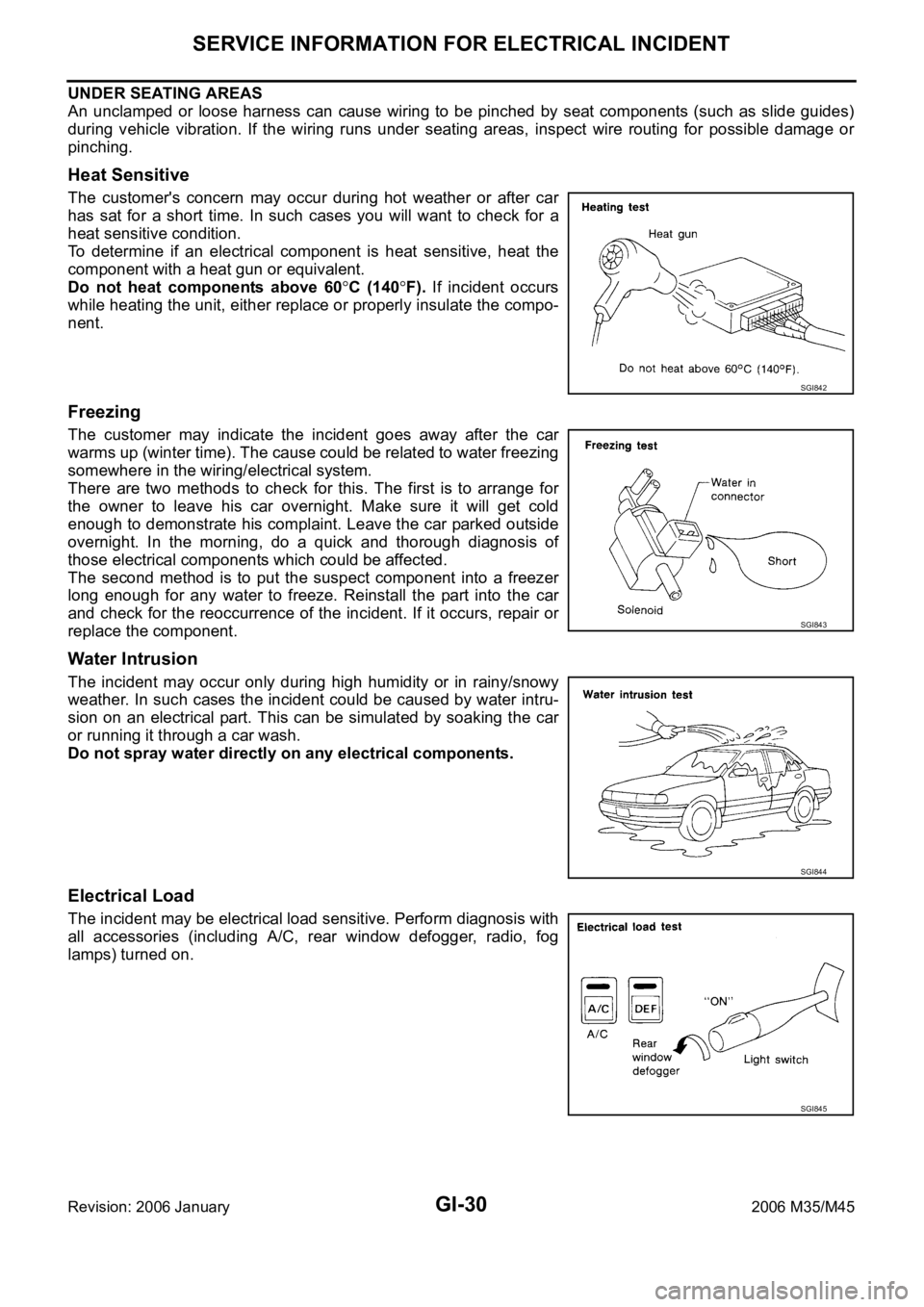
Meter illumination is adjusted to 5 steps by meter illumination control
switch (1) in daytime mode.
Nighttime Mode
Combination meter is transferred to nighttime mode with position light request signal from BCM with CAN
communication.
Meter illumination is adjusted to 16 steps by illumination control
switch (1) in nighttime. Refer to LT- 2 9 5 , "
ILLUMINATION" .
Driver Welcome Function
Ring illumination gradually turns ON when a driver gets in the vehicle with intelligent key and closes the driver
side door.
NOTE:
Ring illumination gradually turns OFF when not turning the ignition switch ON at a certain period of time.
Engine Start Excitement Function
Combination meter detects the engine start when input engine speed signal at first. Pointers of speed meter
and tachometer sweep and ring illumination gradually turns ON when combination meter detects the engine
start. Then, combination meter starts the normal control.
NOTE:
Water temperature gauge and fuel gauge do not function.
Engine start excitement function can be turned ON/OFF with pressing meter illumination control switch for
more than 1 second.
SKIB2623J
SKIB3738E
Page 1442 of 5621

COMBINATION METERS
DI-9
C
D
E
F
G
H
I
J
L
MA
B
DI
Revision: 2006 January2006 M35/M45
FA I L - S A F E
Combination meter performs fail-safe operation when unified meter and A/C amp. communication is malfunc-
tion.
Solution for communication error between the unified meter & A/C amp. and combination meter
Function Specifications
Speedometer
Reset to zero by suspending communication. Tachometer
Fuel gauge
Water temperature gauge
Illumination control Meter illumination When suspending communication, change to nighttime mode.
Dot matrix LCDPush engine starter
The display turns off by suspending communication. A/T position
ICC system
Buzzer The buzzer turns off by suspending communication.
Warning lamp/indicator lampABS warning lamp
The lamp turns on by suspending communication. Brake warning lamp
CRUISE warning lamp
VDC OFF indicator lamp
SLIP indicator lamp
A/T CHECK warning lamp
The lamp turns off by suspending communication. AWD warning lamp
Oil pressure warning lamp
Door warning lamp
Malfunction indicator lamp
CRUISE indicator lamp
SET indicator lamp
Low tire pressure warning lamp
AFS OFF indicator lamp
Front fog indicator lamp
High beam indicator
Turn signal indicator lamp
Key warning lamp
Page 3493 of 5621

GI-30
SERVICE INFORMATION FOR ELECTRICAL INCIDENT
Revision: 2006 January2006 M35/M45
UNDER SEATING AREAS
An unclamped or loose harness can cause wiring to be pinched by seat components (such as slide guides)
during vehicle vibration. If the wiring runs under seating areas, inspect wire routing for possible damage or
pinching.
Heat Sensitive
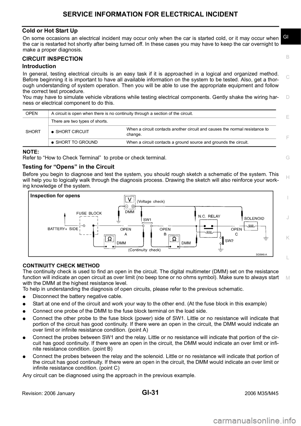
The customer's concern may occur during hot weather or after car
has sat for a short time. In such cases you will want to check for a
heat sensitive condition.
To determine if an electrical component is heat sensitive, heat the
component with a heat gun or equivalent.
Do not heat components above 60
C (140F). If incident occurs
while heating the unit, either replace or properly insulate the compo-
nent.
Freezing
The customer may indicate the incident goes away after the car
warms up (winter time). The cause could be related to water freezing
somewhere in the wiring/electrical system.
There are two methods to check for this. The first is to arrange for
the owner to leave his car overnight. Make sure it will get cold
enough to demonstrate his complaint. Leave the car parked outside
overnight. In the morning, do a quick and thorough diagnosis of
those electrical components which could be affected.
The second method is to put the suspect component into a freezer
long enough for any water to freeze. Reinstall the part into the car
and check for the reoccurrence of the incident. If it occurs, repair or
replace the component.
Water Intrusion
The incident may occur only during high humidity or in rainy/snowy
weather. In such cases the incident could be caused by water intru-
sion on an electrical part. This can be simulated by soaking the car
or running it through a car wash.
Do not spray water directly on any electrical components.
Electrical Load
The incident may be electrical load sensitive. Perform diagnosis with
all accessories (including A/C, rear window defogger, radio, fog
lamps) turned on.
SGI842
SGI843
SGI844
SGI845
Page 3494 of 5621

SERVICE INFORMATION FOR ELECTRICAL INCIDENT
GI-31
C
D
E
F
G
H
I
J
K
L
MB
GI
Revision: 2006 January2006 M35/M45
Cold or Hot Start Up
On some occasions an electrical incident may occur only when the car is started cold, or it may occur when
the car is restarted hot shortly after being turned off. In these cases you may have to keep the car overnight to
make a proper diagnosis.
CIRCUIT INSPECTION
Introduction
In general, testing electrical circuits is an easy task if it is approached in a logical and organized method.
Before beginning it is important to have all available information on the system to be tested. Also, get a thor-
ough understanding of system operation. Then you will be able to use the appropriate equipment and follow
the correct test procedure.
You may have to simulate vehicle vibrations while testing electrical components. Gently shake the wiring har-
ness or electrical component to do this.
NOTE:
Refer to “How to Check Terminal” to probe or check terminal.
Testing for “Opens” in the Circuit
Before you begin to diagnose and test the system, you should rough sketch a schematic of the system. This
will help you to logically walk through the diagnosis process. Drawing the sketch will also reinforce your work-
ing knowledge of the system.
CONTINUITY CHECK METHOD
The continuity check is used to find an open in the circuit. The digital multimeter (DMM) set on the resistance
function will indicate an open circuit as over limit (no beep tone or no ohms symbol). Make sure to always start
with the DMM at the highest resistance level.
To help in understanding the diagnosis of open circuits, please refer to the previous schematic.
Disconnect the battery negative cable.
Start at one end of the circuit and work your way to the other end. (At the fuse block in this example)
Connect one probe of the DMM to the fuse block terminal on the load side.
Connect the other probe to the fuse block (power) side of SW1. Little or no resistance will indicate that
portion of the circuit has good continuity. If there were an open in the circuit, the DMM would indicate an
over limit or infinite resistance condition. (point A)
Connect the probes between SW1 and the relay. Little or no resistance will indicate that portion of the cir-
cuit has good continuity. If there were an open in the circuit, the DMM would indicate an over limit or infi-
nite resistance condition. (point B)
Connect the probes between the relay and the solenoid. Little or no resistance will indicate that portion of
the circuit has good continuity. If there were an open in the circuit, the DMM would indicate an over limit or
infinite resistance condition. (point C)
Any circuit can be diagnosed using the approach in the previous example.
OPEN A circuit is open when there is no continuity through a section of the circuit.
SHORTThere are two types of shorts.
SHORT CIRCUITWhen a circuit contacts another circuit and causes the normal resistance to
change.
SHORT TO GROUND When a circuit contacts a ground source and grounds the circuit.
SGI846-A