2006 INFINITI M35 brake
[x] Cancel search: brakePage 3264 of 5621
![INFINITI M35 2006 Factory Service Manual ROCKER COVER
EM-201
[VK45DE]
C
D
E
F
G
H
I
J
K
L
MA
EM
Revision: 2006 January2006 M35/M45
–No. 10 bolt. See the figure and remove them using a 300 mm
expansion bar.
–No. 12 bolt. See the figure an INFINITI M35 2006 Factory Service Manual ROCKER COVER
EM-201
[VK45DE]
C
D
E
F
G
H
I
J
K
L
MA
EM
Revision: 2006 January2006 M35/M45
–No. 10 bolt. See the figure and remove them using a 300 mm
expansion bar.
–No. 12 bolt. See the figure an](/manual-img/42/57023/w960_57023-3263.png)
ROCKER COVER
EM-201
[VK45DE]
C
D
E
F
G
H
I
J
K
L
MA
EM
Revision: 2006 January2006 M35/M45
–No. 10 bolt. See the figure and remove them using a 300 mm
expansion bar.
–No. 12 bolt. See the figure and remove them using a 300 mm
expansion bar.
NOTE:
Slide the brake piping frontward to obtain working space.
9. Remove rocker cover gaskets from rocker covers.
10. Use scraper to remove all traces of liquid gasket from cylinder head and camshaft bracket (No. 1 and 6).
CAUTION:
Do not scratch or damage the mating surface when cleaning off oil liquid gasket.
INSTALLATION
1. Apply liquid gasket with tube presser [SST: WS39930000 ( —
)] to joint among rocker cover, cylinder head and camshaft
bracket (No. 1 and 6) as follows:
Use Genuine RTV Silicone Sealant or equivalent. Refer to
GI-48, "
RECOMMENDED CHEMICAL PRODUCTS AND
SEALANTS" .
NOTE:
The figure shows an example of left bank side [zoomed in
shows camshaft bracket (No. 1)]. Apply only to camshaft bracket
(No. 1) for right bank side.
a. Refer to the figure “a” to apply liquid gasket to joint part of cam-
shaft bracket (both No. 1 and 6) and cylinder head.
b. Refer to the figure “b” to apply liquid gasket to the figure “a”
squarely.
2. Install new rocker cover gaskets to rocker covers.
3. Install rocker cover.
Check if rocker cover gasket is not dropped from installation groove of rocker cover.
A : Cowl top panel hole
: Engine front
PBIC3367E
A : Cowl top panel hole
: Engine front
PBIC3366E
PBIC2444E
Page 3265 of 5621
![INFINITI M35 2006 Factory Service Manual EM-202
[VK45DE]
ROCKER COVER
Revision: 2006 January2006 M35/M45
4. Tighten mounting bolts in two steps separately in numerical
order as shown in the figure.
CAUTION:
Do not hold oil filler INFINITI M35 2006 Factory Service Manual EM-202
[VK45DE]
ROCKER COVER
Revision: 2006 January2006 M35/M45
4. Tighten mounting bolts in two steps separately in numerical
order as shown in the figure.
CAUTION:
Do not hold oil filler](/manual-img/42/57023/w960_57023-3264.png)
EM-202
[VK45DE]
ROCKER COVER
Revision: 2006 January2006 M35/M45
4. Tighten mounting bolts in two steps separately in numerical
order as shown in the figure.
CAUTION:
Do not hold oil filler neck (right bank) so as not to dam-
age it.
Do not bend or damage brake piping by tools. (ICC mod-
els)
NOTE:
Tighten No. 10 bolt of the right bank and No. 10 and 12 bolts of
the left bank from cowl top panel hole with using tool.
5. Install oil filler cap and oil catcher to rocker cover (right bank), if removed.
6. Install new O-rings and PCV valves to rocker covers (right and left bank), if removed.
7. Install in the reverse order of removal. 1st step : 2.0 Nꞏm (0.2 kg-m, 18 in-lb)
2nd step : 8.3 Nꞏm (0.85 kg-m, 73 in-lb)
PBIC0027E
Page 3277 of 5621
![INFINITI M35 2006 Factory Service Manual EM-214
[VK45DE]
TIMING CHAIN
Revision: 2006 January2006 M35/M45
f. Further tighten by 90 degrees. (Angle tightening)
Check the tightening angle by referencing to the notches. The
angle between two not INFINITI M35 2006 Factory Service Manual EM-214
[VK45DE]
TIMING CHAIN
Revision: 2006 January2006 M35/M45
f. Further tighten by 90 degrees. (Angle tightening)
Check the tightening angle by referencing to the notches. The
angle between two not](/manual-img/42/57023/w960_57023-3276.png)
EM-214
[VK45DE]
TIMING CHAIN
Revision: 2006 January2006 M35/M45
f. Further tighten by 90 degrees. (Angle tightening)
Check the tightening angle by referencing to the notches. The
angle between two notches is 90 degrees.
15. Rotate crankshaft pulley in normal direction (clockwise when viewed from engine front) to confirm it turns
smoothly.
16. Install in the reverse order of removal after this step.
INSPECTION AFTER INSTALLATION
Inspection for Leaks
The following are procedures for checking fluids leak, lubricates leak and exhaust gases leak.
Before starting engine, check oil/fluid levels including engine coolant and engine oil. If less than required
quantity, fill to the specified level. Refer to MA-12, "
RECOMMENDED FLUIDS AND LUBRICANTS" .
Use procedure below to check for fuel leakage.
–Turn ignition switch “ON” (with engine stopped). With fuel pressure applied to fuel piping, check for fuel
leakage at connection points.
–Start engine. With engine speed increased, check again for fuel leakage at connection points.
Run engine to check for unusual noise and vibration.
NOTE:
If hydraulic pressure inside timing chain tensioner drops after removal/installation, slack in guide may gen-
erate a pounding noise during and just after engine start. However, this does not indicate an unusualness.
Noise will stop after hydraulic pressure rises.
Warm up engine thoroughly to make sure there is no leakage of fuel, exhaust gases, or any oil/fluids
including engine oil and engine coolant.
Bleed air from lines and hoses of applicable lines, such as in cooling system.
After cooling down engine, again check oil/fluid levels including engine oil and engine coolant. Refill to the
specified level, if necessary.
Summary of the inspection items:
* Transmission/transaxle/CVT fluid, power steering fluid, brake fluid, etc.
PBIC2346E
Item Before starting engine Engine running After engine stopped
Engine coolant Level Leakage Level
Engine oil Level Leakage Level
Other oils and fluid* Level Leakage Level
Fuel Leakage Leakage Leakage
Exhaust gases — Leakage —
Page 3285 of 5621
![INFINITI M35 2006 Factory Service Manual EM-222
[VK45DE]
CAMSHAFT
Revision: 2006 January2006 M35/M45
4. Crank the engine, and then make sure that engine oil comes out
from intake valve timing control cover oil hole. End crank after INFINITI M35 2006 Factory Service Manual EM-222
[VK45DE]
CAMSHAFT
Revision: 2006 January2006 M35/M45
4. Crank the engine, and then make sure that engine oil comes out
from intake valve timing control cover oil hole. End crank after](/manual-img/42/57023/w960_57023-3284.png)
EM-222
[VK45DE]
CAMSHAFT
Revision: 2006 January2006 M35/M45
4. Crank the engine, and then make sure that engine oil comes out
from intake valve timing control cover oil hole. End crank after
checking.
WA R N I N G :
Be careful not to touch rotating parts (drive belt, idler pul-
ley, and crankshaft pulley, etc.).
CAUTION:
Engine oil may squirt from intake valve timing control sole-
noid valve installation hole during cranking. Use a shop
cloth to prevent the engine components and the vehicle. Do
not allow engine oil to get on rubber components such as
drive belt or engine mount insulators. Immediately wipe off
any splashed engine oil.
Clean oil groove between oil strainer and intake valve timing control solenoid valve if engine oil does not
come out from intake valve timing control cover oil hole. Refer to LU-24, "
LUBRICATION SYSTEM" .
5. Remove components between intake valve timing control solenoid valve and camshaft sprocket (INT),
and then check each oil groove for clogging.
Clean oil groove if necessary. Refer to LU-24, "LUBRICATION SYSTEM" .
6. After inspection, install removed parts.
INSPECTION AFTER INSTALLATION
Inspection for Leaks
The following are procedures for checking fluids leak, lubricates leak and exhaust gases leak.
Before starting engine, check oil/fluid levels including engine coolant and engine oil. If less than required
quantity, fill to the specified level. Refer to MA-12, "
RECOMMENDED FLUIDS AND LUBRICANTS" .
Use procedure below to check for fuel leakage.
–Turn ignition switch “ON” (with engine stopped). With fuel pressure applied to fuel piping, check for fuel
leakage at connection points.
–Start engine. With engine speed increased, check again for fuel leakage at connection points.
Run engine to check for unusual noise and vibration.
NOTE:
If hydraulic pressure inside timing chain tensioner drops after removal/installation, slack in guide may gen-
erate a pounding noise during and just after engine start. However, this does not indicate an unusualness.
Noise will stop after hydraulic pressure rises.
Warm up engine thoroughly to make sure there is no leakage of fuel, exhaust gases, or any oil/fluids
including engine oil and engine coolant.
Bleed air from lines and hoses of applicable lines, such as in cooling system.
After cooling down engine, again check oil/fluid levels including engine oil and engine coolant. Refill to the
specified level, if necessary.
Summary of the inspection items:
* Transmission/transaxle/CVT fluid, power steering fluid, brake fluid, etc.
Valve ClearanceNBS004PB
INSPECTION
In cases of removing/installing or replacing camshaft and valve-related parts, or of unusual engine conditions
due to changes in valve clearance (found malfunctions during starting, idling or causing noise), perform
inspection as follows:
1. Remove rocker covers (right and left bank). Refer to EM-199, "
ROCKER COVER" .
PBIC2848E
Item Before starting engine Engine running After engine stopped
Engine coolant Level Leakage Level
Engine oil Level Leakage Level
Other oils and fluid* Level Leakage Level
Fuel Leakage Leakage Leakage
Exhaust gases — Leakage —
Page 3311 of 5621
![INFINITI M35 2006 Factory Service Manual EM-248
[VK45DE]
ENGINE ASSEMBLY
Revision: 2006 January2006 M35/M45
Summary of the inspection items:
* Transmission/transaxle/CVT fluid, power steering fluid, brake fluid, etc. Item Before starting eng INFINITI M35 2006 Factory Service Manual EM-248
[VK45DE]
ENGINE ASSEMBLY
Revision: 2006 January2006 M35/M45
Summary of the inspection items:
* Transmission/transaxle/CVT fluid, power steering fluid, brake fluid, etc. Item Before starting eng](/manual-img/42/57023/w960_57023-3310.png)
EM-248
[VK45DE]
ENGINE ASSEMBLY
Revision: 2006 January2006 M35/M45
Summary of the inspection items:
* Transmission/transaxle/CVT fluid, power steering fluid, brake fluid, etc. Item Before starting engine Engine running After engine stopped
Engine coolant Level Leakage Level
Engine oil Level Leakage Level
Other oils and fluid* Level Leakage Level
Fuel Leakage Leakage Leakage
Exhaust gases — Leakage —
Page 3363 of 5621

FAX-4
NOISE, VIBRATION AND HARSHNESS (NVH) TROUBLESHOOTING
Revision: 2006 January2006 M35/M45
NOISE, VIBRATION AND HARSHNESS (NVH) TROUBLESHOOTINGPFP:00003
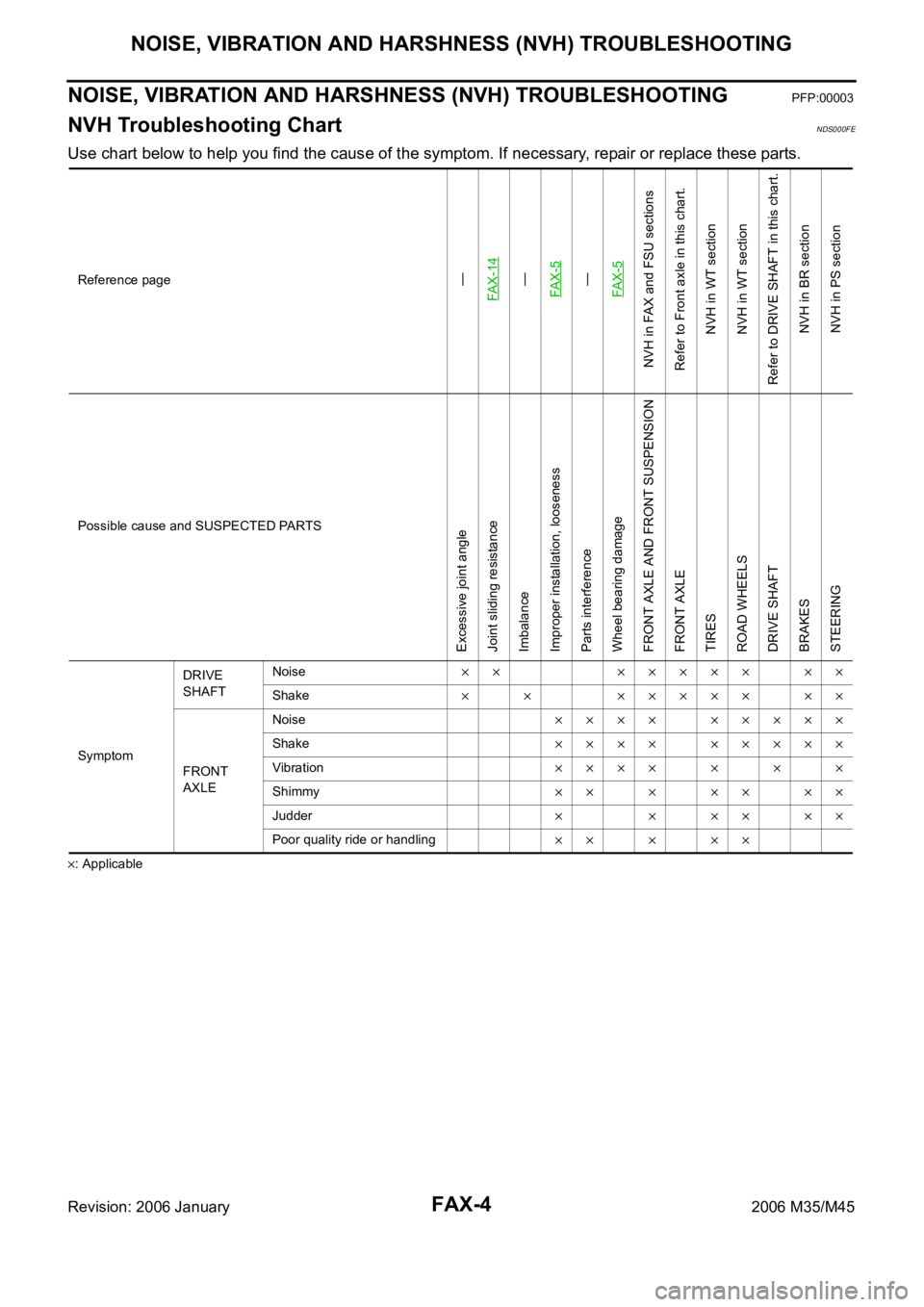
NVH Troubleshooting ChartNDS000FE
Use chart below to help you find the cause of the symptom. If necessary, repair or replace these parts.
: ApplicableReference page
—
FA X - 1 4—
FAX-5—
FAX-5
NVH in FAX and FSU sections
Refer to Front axle in this chart.
NVH in WT section
NVH in WT section
Refer to DRIVE SHAFT in this chart.
NVH in BR section
NVH in PS section
Possible cause and SUSPECTED PARTS
Excessive joint angle
Joint sliding resistance
Imbalance
Improper installation, looseness
Parts interference
Wheel bearing damage
FRONT AXLE AND FRONT SUSPENSION
FRONT AXLE
TIRES
ROAD WHEELS
DRIVE SHAFT
BRAKES
STEERING
SymptomDRIVE
SHAFTNoise
Shake
FRONT
AXLENoise
Shake
Vibration
Shimmy
Judder
Poor quality ride or handling
Page 3364 of 5621

FRONT WHEEL HUB AND KNUCKLE
FAX-5
C
E
F
G
H
I
J
K
L
MA
B
FA X
Revision: 2006 January2006 M35/M45
FRONT WHEEL HUB AND KNUCKLEPFP:40202
On-Vehicle Inspection and ServiceNDS000FF
Make sure that the mounting conditions (looseness, backlash) of each component and component conditions
(wear, damage) are normal.
WHEEL BEARING INSPECTION
Move wheel hub and bearing assembly in the axial direction by hand. Make sure there is no looseness of
wheel bearing.
Rotate wheel hub and make sure that is no unusual noise or other irregular conditions. If there is any of
irregular conditions, replace wheel hub and bearing assembly
Removal and InstallationNDS000FG
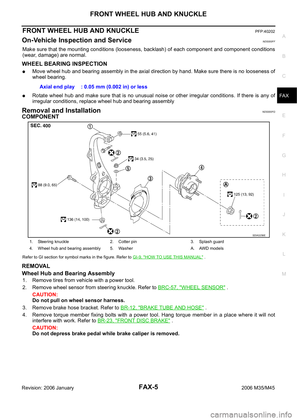
COMPONENT
Refer to GI section for symbol marks in the figure. Refer to GI-9, "HOW TO USE THIS MANUAL" .
REMOVAL
Wheel Hub and Bearing Assembly
1. Remove tires from vehicle with a power tool.
2. Remove wheel sensor from steering knuckle. Refer to BRC-57, "
WHEEL SENSOR" .
CAUTION:
Do not pull on wheel sensor harness.
3. Remove brake hose bracket. Refer to BR-12, "
BRAKE TUBE AND HOSE" .
4. Remove torque member fixing bolts with a power tool. Hang torque member in a place where it will not
interfere with work. Refer to BR-23, "
FRONT DISC BRAKE" .
CAUTION:
Do not depress brake pedal while brake caliper is removed.Axial end play : 0.05 mm (0.002 in) or less
1. Steering knuckle 2. Cotter pin 3. Splash guard
4. Wheel hub and bearing assembly 5. Washer A. AWD models
SDIA3256E
Page 3367 of 5621

FAX-8
FRONT DRIVE SHAFT
Revision: 2006 January2006 M35/M45
FRONT DRIVE SHAFTPFP:39100
On-Vehicle Inspection and ServiceNDS000FH
Check drive shaft mounting point and joint for looseness and other damage.
Check boot for cracks and other damage.
CAUTION:
Replace entire drive shaft assembly when noise or vibration occur from drive shaft.
DRIVE SHAFT BOOT REPLACEMENT
1. Remove tires from vehicle with a power tool.
2. Remove wheel sensor from steering knuckle. Refer to BRC-57, "
WHEEL SENSOR" .
CAUTION:
Do not pull on wheel sensor harness.
3. Remove brake hose bracket. Refer to BR-12, "
BRAKE TUBE AND HOSE" .
4. Remove torque menber fixing bolts with a power tool. Hang torque menber in a place where it will not
interfere with work. Refer to BR-23, "
FRONT DISC BRAKE" .
NOTE:
Do not depress brake pedal while brake caliper is removed.
5. Remove disc rotor. Refer to FA X - 5 , "
Removal and Installation" .
6. Remove cotter pin, then loosen hub lock nut with a power tool.
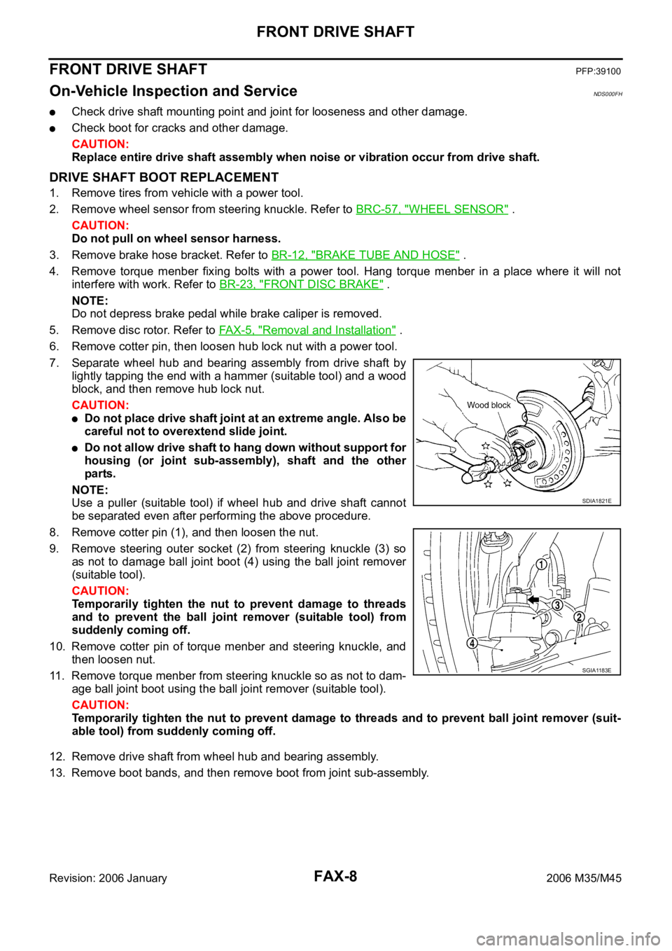
7. Separate wheel hub and bearing assembly from drive shaft by
lightly tapping the end with a hammer (suitable tool) and a wood
block, and then remove hub lock nut.
CAUTION:
Do not place drive shaft joint at an extreme angle. Also be
careful not to overextend slide joint.
Do not allow drive shaft to hang down without support for
housing (or joint sub-assembly), shaft and the other
parts.
NOTE:
Use a puller (suitable tool) if wheel hub and drive shaft cannot
be separated even after performing the above procedure.
8. Remove cotter pin (1), and then loosen the nut.
9. Remove steering outer socket (2) from steering knuckle (3) so
as not to damage ball joint boot (4) using the ball joint remover
(suitable tool).
CAUTION:
Temporarily tighten the nut to prevent damage to threads
and to prevent the ball joint remover (suitable tool) from
suddenly coming off.
10. Remove cotter pin of torque menber and steering knuckle, and
then loosen nut.
11. Remove torque menber from steering knuckle so as not to dam-
age ball joint boot using the ball joint remover (suitable tool).
CAUTION:
Temporarily tighten the nut to prevent damage to threads and to prevent ball joint remover (suit-
able tool) from suddenly coming off.
12. Remove drive shaft from wheel hub and bearing assembly.
13. Remove boot bands, and then remove boot from joint sub-assembly.
SDIA1821E
SGIA1183E