Page 318 of 5621
ON-VEHICLE SERVICE
AT-239
D
E
F
G
H
I
J
K
L
MA
B
AT
Revision: 2006 January2006 M35/M45
14. Remove bolts A, B and C from control valve with TCM.
15. Remove control valve with TCM from transmission case.
CAUTION:
When removing, be careful with the manual valve notch and
manual plate height. Remove it vertically.
16. Remove A/T fluid temperature sensor 2 with bracket from con-
trol valve with TCM.
17. Remove bracket from A/T fluid temperature sensor 2.
18. Remove O-ring from A/T assembly harness connector.
Bolt symbol Length mm (in) Number of bolts
A 42 (1.65) 5
B 55 (2.17) 6
C 40 (1.57) 1
SCIA5139E
SCIA5142E
SCIA5301E
SCIA5264E
SCIA5155E
Page 321 of 5621
AT-242
ON-VEHICLE SERVICE
Revision: 2006 January2006 M35/M45
7. Install control valve with TCM in transmission case.
CAUTION:
Make sure that turbine revolution sensor securely installs
turbine revolution sensor hole.
Hang down revolution sensor harness toward outside so
as not to disturb installation of control valve with TCM.
Adjust A/T assembly harness connector of control valve
with TCM to terminal hole of transmission case.
Assemble it so that manual valve cutout is engaged with
manual plate projection.
8. Install bolts A, B and C in control valve with TCM.
9. Tighten bolt 1, 2 and 3 temporarily to prevent dislocation. After
that tighten them in order (1
2 3), and then tighten other
bolts. Tighten control valve with TCM bolts to the specified
torque. Refer to AT-236, "
COMPONENTS" .
SCIA5034E
SCIA5142E
Bolt symbol Length mm (in) Number of bolts
A 42 (1.65) 5
B 55 (2.17) 6
C 40 (1.57) 1
SCIA5139E
SCIA5140E
Page 353 of 5621

AT-274
TRANSMISSION ASSEMBLY
Revision: 2006 January2006 M35/M45
INSPECTION
Installation and Inspection of Torque Converter
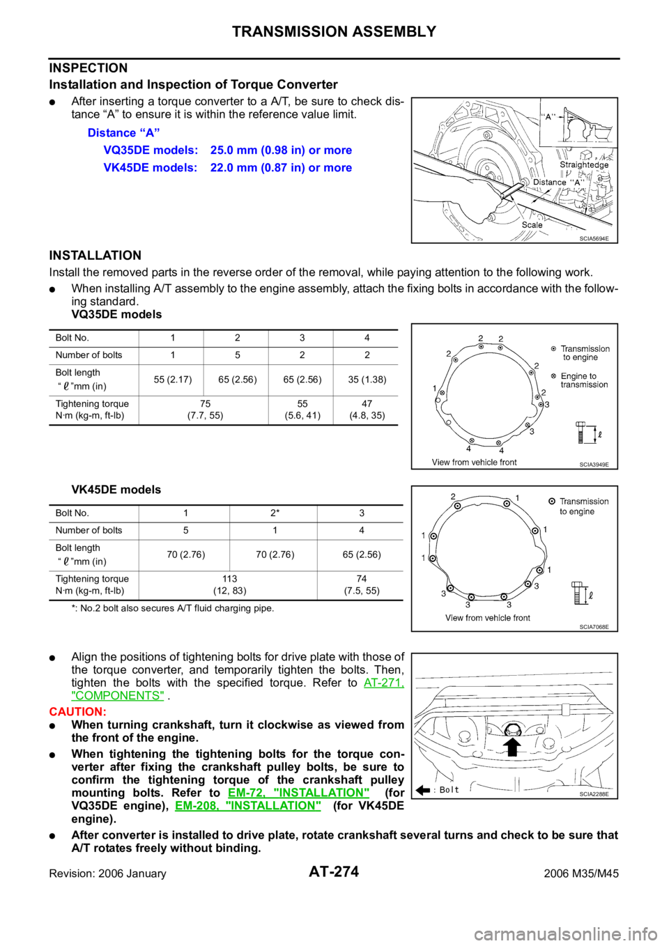
After inserting a torque converter to a A/T, be sure to check dis-
tance “A” to ensure it is within the reference value limit.
INSTALLATION
Install the removed parts in the reverse order of the removal, while paying attention to the following work.
When installing A/T assembly to the engine assembly, attach the fixing bolts in accordance with the follow-
ing standard.
VQ35DE models
VK45DE models
*: No.2 bolt also secures A/T fluid charging pipe.
Align the positions of tightening bolts for drive plate with those of
the torque converter, and temporarily tighten the bolts. Then,
tighten the bolts with the specified torque. Refer to AT- 2 7 1 ,
"COMPONENTS" .
CAUTION:
When turning crankshaft, turn it clockwise as viewed from
the front of the engine.
When tightening the tightening bolts for the torque con-
verter after fixing the crankshaft pulley bolts, be sure to
confirm the tightening torque of the crankshaft pulley
mounting bolts. Refer to EM-72, "
INSTALLATION" (for
VQ35DE engine), EM-208, "
INSTALLATION" (for VK45DE
engine).
After converter is installed to drive plate, rotate crankshaft several turns and check to be sure that
A/T rotates freely without binding.Distance “A”
VQ35DE models: 25.0 mm (0.98 in) or more
VK45DE models: 22.0 mm (0.87 in) or more
SCIA5694E
Bolt No. 1234
Number of bolts 1 5 2 2
Bolt length
“ ”mm (in)55 (2.17) 65 (2.56) 65 (2.56) 35 (1.38)
Tightening torque
Nꞏm (kg-m, ft-lb)75
(7.7, 55)55
(5.6, 41)47
(4.8, 35)
SCIA3949E
Bolt No. 1 2* 3
Number of bolts 5 1 4
Bolt length
“ ”mm (in)70 (2.76) 70 (2.76) 65 (2.56)
Tightening torque
Nꞏm (kg-m, ft-lb)11 3
(12, 83)74
(7.5, 55)
SCIA7068E
SCIA2288E
Page 356 of 5621

TRANSMISSION ASSEMBLY
AT-277
D
E
F
G
H
I
J
K
L
MA
B
AT
Revision: 2006 January2006 M35/M45
INSPECTION
Installation and Inspection of Torque Converter
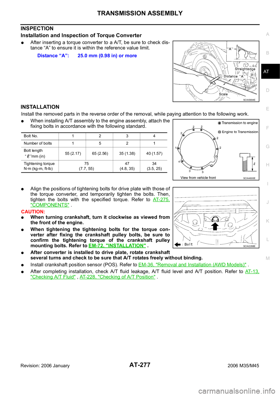
After inserting a torque converter to a A/T, be sure to check dis-
tance “A” to ensure it is within the reference value limit.
INSTALLATION
Install the removed parts in the reverse order of the removal, while paying attention to the following work.
When installing A/T assembly to the engine assembly, attach the
fixing bolts in accordance with the following standard.
Align the positions of tightening bolts for drive plate with those of
the torque converter, and temporarily tighten the bolts. Then,
tighten the bolts with the specified torque. Refer to AT- 2 7 5 ,
"COMPONENTS" .
CAUTION:
When turning crankshaft, turn it clockwise as viewed from
the front of the engine.
When tightening the tightening bolts for the torque con-
verter after fixing the crankshaft pulley bolts, be sure to
confirm the tightening torque of the crankshaft pulley
mounting bolts. Refer to EM-72, "
INSTALLATION" .
After converter is installed to drive plate, rotate crankshaft
several turns and check to be sure that A/T rotates freely without binding.
Install crankshaft position sensor (POS). Refer to EM-36, "Removal and Installation (AWD Models)" .
After completing installation, check A/T fluid leakage, A/T fluid level and A/T position. Refer to AT- 1 3 ,
"Checking A/T Fluid" , AT-228, "Checking of A/T Position" . Distance “A”: 25.0 mm (0.98 in) or more
SCIA5694E
Bolt No. 1 2 3 4
Number of bolts 1 5 2 1
Bolt length
“ ”mm (in)55 (2.17) 65 (2.56) 35 (1.38) 40 (1.57)
Tightening torque
Nꞏm (kg-m, ft-lb)75
(7.7, 55)47
(4.8, 35)34
(3.5, 25)
SCIA4600E
SCIA2288E
Page 384 of 5621
DISASSEMBLY
AT-305
D
E
F
G
H
I
J
K
L
MA
B
AT
Revision: 2006 January2006 M35/M45
33. Disconnect revolution sensor connector.
CAUTION:
Be careful not to damage connector.
34. Straighten terminal clip to free revolution sensor harness.
35. Remove bolts A, B and C from control valve with TCM.
36. Remove control valve with TCM from transmission case.
CAUTION:
When removing, be careful with the manual valve notch and
manual plate height. Remove it vertically.
37. Remove A/T fluid temperature sensor 2 with bracket from con-
trol valve with TCM.
SCIA7524E
SCIA7526E
Bolt symbol Length mm (in) Number of bolts
A 42 (1.65) 5
B 55 (2.17) 6
C 40 (1.57) 1
SCIA5025E
SCIA5260E
SCIA5301E
Page 441 of 5621
AT-362
ASSEMBLY
Revision: 2006 January2006 M35/M45
h. Install bolts A, B and C to control valve with TCM.
i. Tighten bolt 1, 2 and 3 temporarily to prevent dislocation. After
that tighten them in order (1
2 3), and then tighten other
bolts. Tighten control valve bolts to the TCM with specified
torque. Refer to AT-278, "
Components" .
10. Connect A/T fluid temperature sensor 2 connector.
11. Securely fasten terminal cord assembly and A/T fluid tempera-
ture sensor 2 harness with terminal clips.
12. Connect revolution sensor connector.
Bolt symbol Length mm (in) Number of bolts
A 42 (1.65) 5
B 55 (2.17) 6
C 40 (1.57) 1
SCIA5025E
SCIA5037E
SCIA5023E
SCIA5446E
SCIA7524E
Page 1236 of 5621
BODY REPAIR
BL-297
C
D
E
F
G
H
J
K
L
MA
B
BL
Revision: 2006 January2006 M35/M45
DESCRIPTION
All dimensions indicated in the figures are actual.
When using a tracking gauge, adjust both pointers to equal length. Then check the pointers and gauge
itself to make sure there is no free play.
When a measuring tape is used, check to be sure there is no elongation, twisting or bending.
Measurements should be taken at the center of the mounting holes.
An asterisk (*) following the value at the measuring point indicates that the measuring point on the other
side is symmetrically the same value.
The coordinates of the measurement points are the distances measured from the standard line of X, Y
and Z.
PIIA0104E
Page 1283 of 5621

BR-8
BRAKE PEDAL
Revision: 2006 January2006 M35/M45
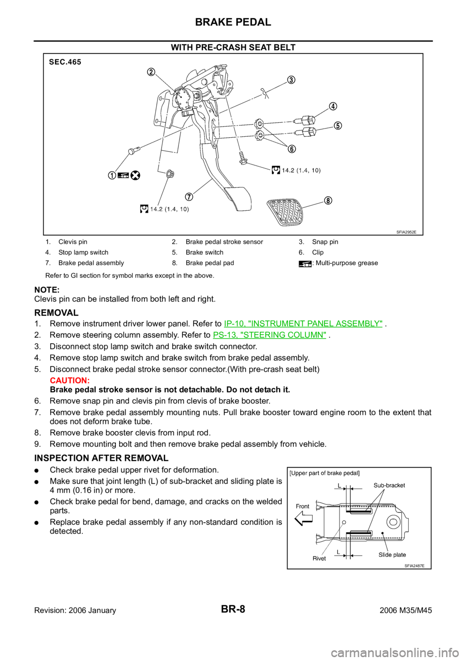
WITH PRE-CRASH SEAT BELT
NOTE:
Clevis pin can be installed from both left and right.
REMOVAL
1. Remove instrument driver lower panel. Refer to IP-10, "INSTRUMENT PANEL ASSEMBLY" .
2. Remove steering column assembly. Refer to PS-13, "
STEERING COLUMN" .
3. Disconnect stop lamp switch and brake switch connector.
4. Remove stop lamp switch and brake switch from brake pedal assembly.
5. Disconnect brake pedal stroke sensor connector.(With pre-crash seat belt)
CAUTION:
Brake pedal stroke sensor is not detachable. Do not detach it.
6. Remove snap pin and clevis pin from clevis of brake booster.
7. Remove brake pedal assembly mounting nuts. Pull brake booster toward engine room to the extent that
does not deform brake tube.
8. Remove brake booster clevis from input rod.
9. Remove mounting bolt and then remove brake pedal assembly from vehicle.
INSPECTION AFTER REMOVAL
Check brake pedal upper rivet for deformation.
Make sure that joint length (L) of sub-bracket and sliding plate is
4 mm (0.16 in) or more.
Check brake pedal for bend, damage, and cracks on the welded
parts.
Replace brake pedal assembly if any non-standard condition is
detected.
SFIA2952E
1. Clevis pin 2. Brake pedal stroke sensor 3. Snap pin
4. Stop lamp switch 5. Brake switch 6. Clip
7. Brake pedal assembly 8. Brake pedal pad : Multi-purpose grease
Refer to GI section for symbol marks except in the above.
SFIA2487E