2006 INFINITI M35 wiper fluid
[x] Cancel search: wiper fluidPage 16 of 5621
![INFINITI M35 2006 Factory Service Manual DESCRIPTION
ACS-7
[ICC]
C
D
E
F
G
H
I
J
L
MA
B
ACS
Revision: 2006 January2006 M35/M45
Components DescriptionNKS004CH
CAN CommunicationNKS004CI
CAN (Controller Area Network) is a serial communication l INFINITI M35 2006 Factory Service Manual DESCRIPTION
ACS-7
[ICC]
C
D
E
F
G
H
I
J
L
MA
B
ACS
Revision: 2006 January2006 M35/M45
Components DescriptionNKS004CH
CAN CommunicationNKS004CI
CAN (Controller Area Network) is a serial communication l](/manual-img/42/57023/w960_57023-15.png)
DESCRIPTION
ACS-7
[ICC]
C
D
E
F
G
H
I
J
L
MA
B
ACS
Revision: 2006 January2006 M35/M45
Components DescriptionNKS004CH
CAN CommunicationNKS004CI
CAN (Controller Area Network) is a serial communication line for real time application. It is an on-vehicle mul-
tiplex communication line with high data communication speed and excellent error detection ability. Many elec-
tric control units are equipped onto a vehicle, and each control unit shares information and links with other
control units during operation (not independent). In CAN communication, control units are connected with 2
communication lines (CAN H line, CAN L line) allowing a high rate of information transmission with less wiring.
Each control unit transmits/receives data but selectively reads required data only.
CAN COMMUNICATION UNIT
Refer to LAN-34, "CAN Communication Unit" .
ComponentVehicle-to-
vehicle
distance
control modeConventional
(fixed speed)
cruise
control modeBrake assist
(with pre-
view func-
tion)Description
ICC sensor integrated unit
Controls vehicle distance by operating electric throttle
control actuator based on that sensor signals and
CAN communication data.
Controls vehicle distance by transmitting deceleration
degree commandment value signal to ABS actuator
and electric unit (control unit) when deceleration with
brake is needed.
Irradiates laser beam, and receives reflected laser
beam to measure distance from preceding vehicle.
ECM
Transmits accelerator pedal position signal, ICC brake
switch signal, stop lamp switch signal and ICC steering
switch signal to ICC sensor integrated unit through CAN
communication.
ABS actuator and electric
unit (control unit)
Transmits vehicle speed signal (wheel speed) and
stop lamp switch signal to ICC sensor integrated unit
through CAN communication.
Receives Deceleration degree commandment value
signal from ICC sensor integrated unit, and controls
brake fluid pressure with the ABS motor.
BCM
Transmits front wiper request signal to ICC sensor inte-
grated unit through CAN communication.
TCM
Transmits gear position signal and output shaft revolu-
tion signal to ICC sensor integrated unit through CAN
communication.
Unified meter and A/C amp.
Receives meter display signal, ICC warning lamp signal
and buzzer output signal from ICC sensor integrated
unit through CAN communication.
ICC brake switch
Transmits operating signal to ECM when depressing
brake pedal. ICC sensor integrated unit cancels cruise
system at driver's brake operation.
Stop lamp switch
Transmits operating signal to ECM and ABS actuator
and electric unit (control unit) when depressing brake
pedal. ICC sensor integrated unit cancels cruise system
at driver's brake operation.
Page 3645 of 5621

IDX-4
ALPHABETICAL INDEX
Electronic ignition (EI) system ............. EC-33, EC-743
Engine control module (ECM) .......... EC-496, EC-1215
Engine control system diagram ........... EC-30, EC-740
Engine coolant temperature sensor (ECTS) ... EC-226,
EC-238
, EC-948, EC-961
Engine coolant(VK45DE) .................................. CO-40
Engine coolant(VQ35DE) ................................. CO-11
Engine oil filter replacement ............................. MA-26
Engine oil filter replacement(VQ35DE) ............. MA-19
Engine oil precautions .......................................... GI-8
Engine oil replacement(VQ35DE) ..................... MA-18
Engine oil(VK45DE) ........................................... LU-26
Engine oil(VQ35DE) ............................................ LU-7
Engine removal(VK45DE) ............................... EM-244
Engine removal(VQ35DE) .............................. EM-113
Engine room cover ............................................ EM-14
Engine room cover(VK45DE) ......................... EM-173
ETC1 - Wiring diagram .................... EC-614, EC-1345
ETC2 - Wiring diagram .................... EC-609, EC-1340
ETC3 - Wiring diagram .................... EC-620, EC-1352
EVAP canister ...................................... EC-42, EC-752
EVAP canister purge volume control solenoid valve ....
EC-412
, EC-420, EC-1132, EC-1140
EVAP canister vent control valve ...... EC-427, EC-434,
EC-1147
, EC-1154
EVAP control system (small leak) diagnosis .. EC-403,
EC-466
, EC-1124, EC-1185
EVAP control system pressure sensor ........... EC-440,
EC-443
, EC-450, EC-1160, EC-1163, EC-1170
EVAP control system purge flow monitoring diagnosis
EC-398
, EC-1119
EVAP vapor lines inspection ................. MA-21, MA-28
Evaporative emission (EVAP) system . EC-39, EC-749
Evaporator ..................................................... ATC-168
Exhaust manifold(VK45DE) ............................ EM-183
Exhaust system ................................................... EX-3
Exhaust system inspection ..................... EX-3, MA-29
Expansion valve ............................................. ATC-169
F
F/FOG - Wiring diagram ................................... LT-197
F/PUMP - Wiring diagram ................ EC-686, EC-1428
Final drive pre-inspection .................. FFD-16, RFD-19
Final drive removal and installation .. FFD-13, RFD-16
Floor trim ............................................................. EI-50
Flow charts ......................................................... GI-28
Fluid temperature sensor (A/T) ........................ AT-135
Fluorescent leak detector .............................. ATC-170
FPCM - Wiring diagram ................... EC-527, EC-1253
Freeze frame data ............................... EC-59, EC-770
Front brake solenoid valve ................. AT-151, AT-153
Front bumper ...................................................... EI-11
Front combination lamp removal and installation LT-76
Front door ............................. BL-190, BL-196, GW-63
Front passenger air bag .................................. SRS-42
Front seat belt .................................................... SB-30
Front seat belt pre-tensioner ..... SB-2, SRS-3, SRS-47
Front washer ...................................................... WW-4
Front wiper ......................................................... WW-4
FTS - Wiring diagram ....................................... AT-136
FTTS - Wiring diagram .... EC-345, EC-350, EC-1068,
EC-1073
Fuel cut control (at no load high engine speed) EC-34,
EC-744
Fuel filter replacement ......................................... FL-4
Fuel gauge ............................................................ DI-5
Fuel injection system (Bank 1) ......... EC-321, EC-332,
EC-1044
, EC-1055
Fuel injection system (Bank 2) ......... EC-321, EC-332,
EC-1044
, EC-1055
Fuel injector ................................................... EC-1420
Fuel injector and fuel tube(VK45DE) .............. EM-193
Fuel injector and fuel tube(VQ35DE) ................ EM-45
Fuel level sensor EC-475, EC-477, EC-479, EC-1194,
EC-1196
, EC-1198
Fuel line inspection .................................. FL-3, MA-25
Fuel line inspection(VQ35DE) .......................... MA-18
Fuel precautions ................................................... GI-6
Fuel pressure check ........................... EC-98, EC-809
Fuel pressure release ......................... EC-98, EC-809
Fuel pump ....................................... EC-685, EC-1427
Fuel pump and gauge .......................................... FL-4
Fuel pump control module .............. EC-525, EC-1251
Fuel pump dropping resistor ........... EC-525, EC-1251
Fuel system ......................................................... FL-3
Fuel tank ............................................................ FL-10
Fuel tank temperature sensor .......... EC-343, EC-349,
EC-1066
, EC-1072
Fuel tank vacuum relief valve ............. EC-42, EC-752
FUELB1 - Wiring diagram EC-323, EC-334, EC-1046,
EC-1057
FUELB2 - Wiring diagram EC-325, EC-336, EC-1048,
EC-1059
Fuse .................................................................. PG-17
Fuse and fusible link box ................................ PG-112
Fusible link ........................................................ PG-17
G
Gauges ................................................................. DI-5
Generator ........................................................... SC-23
Generator - See Alternator ................................ SC-23
Glass ........................ GW-11, GW-61, GW-63, GW-67
Grille - See Exterior ............................................ EI-16
Ground distribution ........................................... PG-46
H
H/LAMP - Wiring diagram ....................... LT-13
, LT-48
Harness connector .......................................... PG-102
Harness layout .................................................. PG-63
Hazard warning lamp ....................................... LT-211
Headlamp removal and installation .................... LT-76
Headlining - See Roof trim .................................. EI-52
Heated oxygen sensor 2 (bank 1) .... EC-286, EC-297,
EC-310
, EC-1009, EC-1020, EC-1033
Heated oxygen sensor 2 (bank 2) .... EC-286, EC-297,
Page 5609 of 5621

WW-42
FRONT WIPER AND WASHER SYSTEM
Revision: 2006 January2006 M35/M45
Removal and Installation of Front Wiper Arms, Adjustment of Wiper Arms Stop
Location
NKS003WY
REMOVAL
1. Turn wiper switch ON to operate wiper motor, and then turn wiper switch OFF (auto stop).
2. Open hood, remove arm caps, and remove wiper arm nuts.
3. Raise wiper arm, and remove wiper arm from the vehicle.
INSTALLATION
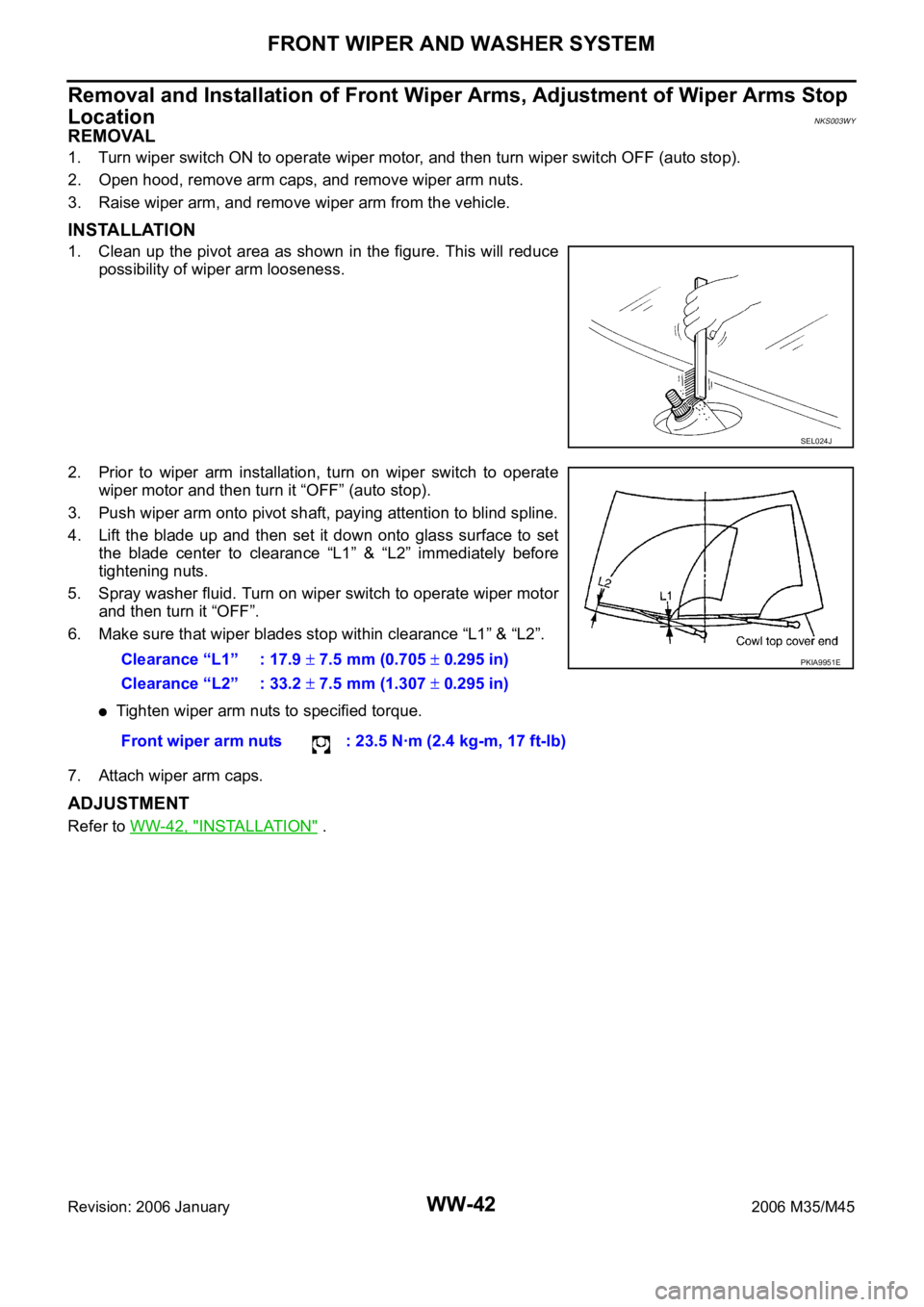
1. Clean up the pivot area as shown in the figure. This will reduce
possibility of wiper arm looseness.
2. Prior to wiper arm installation, turn on wiper switch to operate
wiper motor and then turn it “OFF” (auto stop).
3. Push wiper arm onto pivot shaft, paying attention to blind spline.
4. Lift the blade up and then set it down onto glass surface to set
the blade center to clearance “L1” & “L2” immediately before
tightening nuts.
5. Spray washer fluid. Turn on wiper switch to operate wiper motor
and then turn it “OFF”.
6. Make sure that wiper blades stop within clearance “L1” & “L2”.
Tighten wiper arm nuts to specified torque.
7. Attach wiper arm caps.
ADJUSTMENT
Refer to WW-42, "INSTALLATION" .
SEL024J
Clearance “L1” : 17.9 7.5 mm (0.705 0.295 in)
Clearance “L2” : 33.2
7.5 mm (1.307 0.295 in)
Front wiper arm nuts : 23.5 Nꞏm (2.4 kg-m, 17 ft-lb)
PKIA9951E
Page 5614 of 5621

FRONT WIPER AND WASHER SYSTEM
WW-47
C
D
E
F
G
H
I
J
L
MA
B
WW
Revision: 2006 January2006 M35/M45
Removal and Installation of Washer TankNKS003X7
: Vehicle front
REMOVAL
1. Remove engine room cover (RH). Refer to EM-14, "Removal and Installation" .
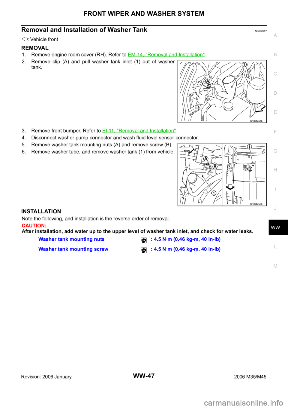
2. Remove clip (A) and pull washer tank inlet (1) out of washer
tank.
3. Remove front bumper. Refer to EI-11, "
Removal and Installation" .
4. Disconnect washer pump connector and wash fluid level sensor connector.
5. Remove washer tank mounting nuts (A) and remove screw (B).
6. Remove washer tube, and remove washer tank (1) from vehicle.
INSTALLATION
Note the following, and installation is the reverse order of removal.
CAUTION:
After installation, add water up to the upper level of washer tank inlet, and check for water leaks.
SKIB4258E
SKIB4259E
Washer tank mounting nuts : 4.5 Nꞏm (0.46 kg-m, 40 in-lb)
Washer tank mounting screw : 4.5 Nꞏm (0.46 kg-m, 40 in-lb)