2006 INFINITI M35 run flat
[x] Cancel search: run flatPage 750 of 5621
![INFINITI M35 2006 Factory Service Manual TROUBLE DIAGNOSIS
AV-129
[WITHOUT MOBILE ENTERTAINMENT SYSTEM]
C
D
E
F
G
H
I
J
L
MA
B
AV
Revision: 2006 January2006 M35/M45
VEHICLE MARK IS IN A RIVER OR SEA
The navigation system moves the vehicle ma INFINITI M35 2006 Factory Service Manual TROUBLE DIAGNOSIS
AV-129
[WITHOUT MOBILE ENTERTAINMENT SYSTEM]
C
D
E
F
G
H
I
J
L
MA
B
AV
Revision: 2006 January2006 M35/M45
VEHICLE MARK IS IN A RIVER OR SEA
The navigation system moves the vehicle ma](/manual-img/42/57023/w960_57023-749.png)
TROUBLE DIAGNOSIS
AV-129
[WITHOUT MOBILE ENTERTAINMENT SYSTEM]
C
D
E
F
G
H
I
J
L
MA
B
AV
Revision: 2006 January2006 M35/M45
VEHICLE MARK IS IN A RIVER OR SEA
The navigation system moves the vehicle mark with no distinction between land and rivers or sea. If the vehi-
cle mark is somehow out of place, it may appear that the vehicle is driving in a river or the sea.
VEHICLE MARK AUTOMATICALLY ROTATES
The system wrongly memorizes the rotating status as stopping when the ignition switch is turned ON with the
turntable rotating. That causes the vehicle mark to rotate when the vehicle is stopped.
WHEN DRIVING ON SAME ROAD, SOMETIMES VEHICLE MARK IS IN RIGHT PLACE AND
SOMETIMES IT IS WRONG PLACE
The conditions of the GPS antenna (GPS data) and gyroscope (angular speed sensor) change gradually.
Depending on the road traveled and the operation of the steering wheel, the location detection results will be
different. Therefore, even on a road on which the location has never been wrong, conditions may cause the
vehicle mark to deviate.
LOCATION CORRECTION BY MAP-MATCHING IS SLOW
The map matching function needs to refer to the data of the surrounding area. It is necessary to drive
some distance for the function to work.
Because map matching operates on this principle, when there are many roads running in similar direc-
tions in the surrounding area, no matching determination may be made. The location may not be cor-
rected until some special feature is found.
ALTHOUGH GPS RECEIVING DISPLAY IS GREEN, VEHICLE MARK DOES NOT RETURN TO
CORRECT LOCATION
The GPS accuracy has an error of approximately 10 m (30 ft). In some cases the vehicle mark may not be
on the correct street, even when GPS location-correction is done.
The navigation system compares the results of GPS location detection with the results from map-match-
ing location detection. The one which is determined to have higher accuracy is used.
GPS location correction may not be performed when the vehicle is stopped.
NAME OF CURRENT PLACE IS NOT DISPLAYED
The current place name may not be displayed if there are no place names displayed on the map screen.
CONTENTS OF DISPLAY DIFFER FOR BIRDVIEW® AND THE (FLAT) MAP SCREEN
Difference of the BIRDVIEW
® Screen From the Flat Map Screen Are As Follows
The current place name displays names which are primarily in the direction of vehicle travel.
The amount of time before the vehicle travel or turn angle is updated on the screen is longer than for the
(flat) map display.
The conditions for display of place names, roads, and other data are different for nearby areas and for
more distant areas.
Some thinning of the character data is done to prevent the display becoming to complex. In some cases
and in some locations, the display contents may differ.
The same place name, street name, etc. may be displayed multiple times.
Page 905 of 5621
![INFINITI M35 2006 Factory Service Manual AV-284
[WITH MOBILE ENTERTAINMENT SYSTEM]
TROUBLE DIAGNOSIS
Revision: 2006 January2006 M35/M45
VEHICLE MARK IS IN A RIVER OR SEA
The navigation system moves the vehicle mark with no distinction betwee INFINITI M35 2006 Factory Service Manual AV-284
[WITH MOBILE ENTERTAINMENT SYSTEM]
TROUBLE DIAGNOSIS
Revision: 2006 January2006 M35/M45
VEHICLE MARK IS IN A RIVER OR SEA
The navigation system moves the vehicle mark with no distinction betwee](/manual-img/42/57023/w960_57023-904.png)
AV-284
[WITH MOBILE ENTERTAINMENT SYSTEM]
TROUBLE DIAGNOSIS
Revision: 2006 January2006 M35/M45
VEHICLE MARK IS IN A RIVER OR SEA
The navigation system moves the vehicle mark with no distinction between land and rivers or sea. If the vehi-
cle mark is somehow out of place, it may appear that the vehicle is driving in a river or the sea.
VEHICLE MARK AUTOMATICALLY ROTATES
The system wrongly memorizes the rotating status as stopping when the ignition switch is turned ON with the
turntable rotating. That causes the vehicle mark to rotate when the vehicle is stopped.
WHEN DRIVING ON SAME ROAD, SOMETIMES VEHICLE MARK IS IN RIGHT PLACE AND
SOMETIMES IT IS WRONG PLACE
The conditions of the GPS antenna (GPS data) and gyroscope (angular speed sensor) change gradually.
Depending on the road traveled and the operation of the steering wheel, the location detection results will be
different. Therefore, even on a road on which the location has never been wrong, conditions may cause the
vehicle mark to deviate.
LOCATION CORRECTION BY MAP-MATCHING IS SLOW
The map matching function needs to refer to the data of the surrounding area. It is necessary to drive
some distance for the function to work.
Because map matching operates on this principle, when there are many roads running in similar direc-
tions in the surrounding area, no matching determination may be made. The location may not be cor-
rected until some special feature is found.
ALTHOUGH GPS RECEIVING DISPLAY IS GREEN, VEHICLE MARK DOES NOT RETURN TO
CORRECT LOCATION
The GPS accuracy has an error of approximately 10 m (30 ft). In some cases the vehicle mark may not be
on the correct street, even when GPS location-correction is done.
The navigation system compares the results of GPS location detection with the results from map-match-
ing location detection. The one which is determined to have higher accuracy is used.
GPS location correction may not be performed when the vehicle is stopped.
NAME OF CURRENT PLACE IS NOT DISPLAYED
The current place name may not be displayed if there are no place names displayed on the map screen.
CONTENTS OF DISPLAY DIFFER FOR BIRDVIEW® AND THE (FLAT) MAP SCREEN
Difference of the BIRDVIEW
® Screen From the Flat Map Screen Are As Follows
The current place name displays names which are primarily in the direction of vehicle travel.
The amount of time before the vehicle travel or turn angle is updated on the screen is longer than for the
(flat) map display.
The conditions for display of place names, roads, and other data are different for nearby areas and for
more distant areas.
Some thinning of the character data is done to prevent the display becoming to complex. In some cases
and in some locations, the display contents may differ.
The same place name, street name, etc. may be displayed multiple times.
Page 1143 of 5621

BL-204
TRUNK LID
Revision: 2006 January2006 M35/M45
Loosen the striker mounting bolts.
Lift up the trunk lid approx. 100 - 150 mm (3.94 - 5.91 in) height then close it lightly and make sure it
engaged firmly with the trunk lid closed.
Check the clearance and evenness.
Finally tighten the trunk lid striker.
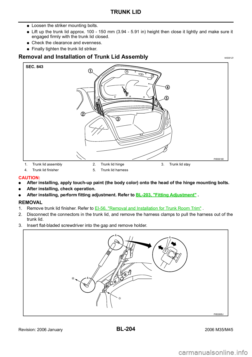
Removal and Installation of Trunk Lid AssemblyNIS001ZI
CAUTION:
After installing, apply touch-up paint (the body color) onto the head of the hinge mounting bolts.
After installing, check operation.
After installing, perform fitting adjustment. Refer to BL-203, "Fitting Adjustment" .
REMOVAL
1. Remove trunk lid finisher. Refer to EI-56, "Removal and Installation for Trunk Room Trim" .
2. Disconnect the connectors in the trunk lid, and remove the harness clamps to pull the harness out of the
trunk lid.
3. Insert flat-bladed screwdriver into the gap and remove holder.
1. Trunk lid assembly 2. Trunk lid hinge 3. Trunk lid stay
4. Trunk lid finisher 5. Trunk lid harness
PIIB5818E
PIIB3895J
Page 1144 of 5621

TRUNK LID
BL-205
C
D
E
F
G
H
J
K
L
MA
B
BL
Revision: 2006 January2006 M35/M45
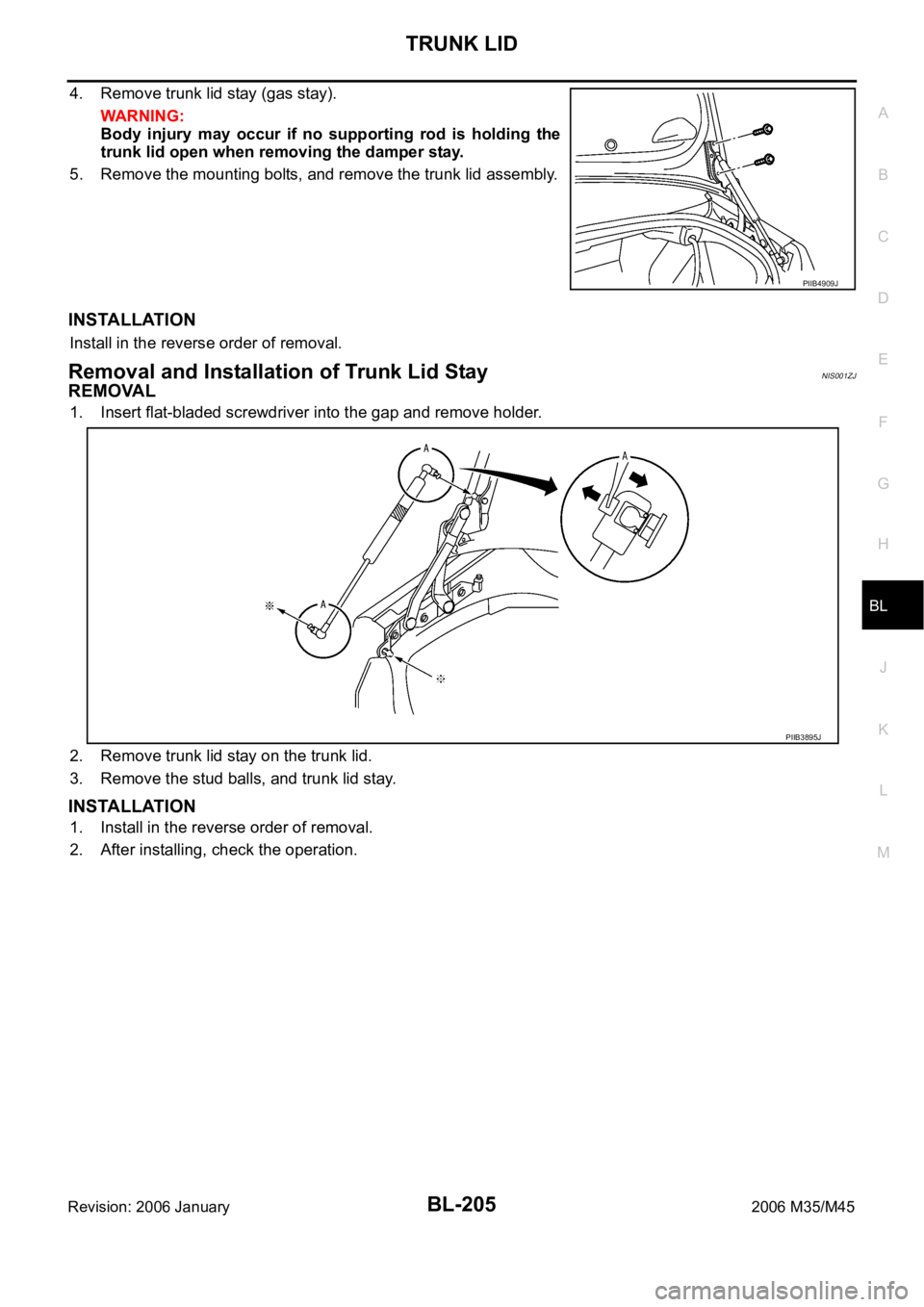
4. Remove trunk lid stay (gas stay).
WAR NING :
Body injury may occur if no supporting rod is holding the
trunk lid open when removing the damper stay.
5. Remove the mounting bolts, and remove the trunk lid assembly.
INSTALLATION
Install in the reverse order of removal.
Removal and Installation of Trunk Lid StayNIS001ZJ
REMOVAL
1. Insert flat-bladed screwdriver into the gap and remove holder.
2. Remove trunk lid stay on the trunk lid.
3. Remove the stud balls, and trunk lid stay.
INSTALLATION
1. Install in the reverse order of removal.
2. After installing, check the operation.
PIIB4909J
PIIB3895J
Page 1303 of 5621

BR-28
FRONT DISC BRAKE
Revision: 2006 January2006 M35/M45
DISC ROTOR INSPECTION
Visual Inspection
Check surface of disc rotor for uneven wear, cracks, and serious damage. Replace if there are.
Runout Inspection
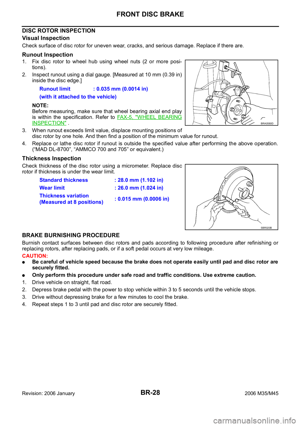
1. Fix disc rotor to wheel hub using wheel nuts (2 or more posi-
tions).
2. Inspect runout using a dial gauge. [Measured at 10 mm (0.39 in)
inside the disc edge.]
NOTE:
Before measuring, make sure that wheel bearing axial end play
is within the specification. Refer to FA X - 5 , "
WHEEL BEARING
INSPECTION" .
3. When runout exceeds limit value, displace mounting positions of
disc rotor by one hole. And then find a position of the minimum value for runout.
4. Replace or lathe disc rotor if runout is outside the specified value after performing the above operation.
(“MAD DL-8700”, “AMMCO 700 and 705” or equivalent.)
Thickness Inspection
Check thickness of the disc rotor using a micrometer. Replace disc
rotor if thickness is under the wear limit.
BRAKE BURNISHING PROCEDURE
Burnish contact surfaces between disc rotors and pads according to following procedure after refinishing or
replacing rotors, after replacing pads, or if a soft pedal occurs at very low mileage.
CAUTION:
Be careful of vehicle speed because the brake does not operate easily until pad and disc rotor are
securely fitted.
Only perform this procedure under safe road and traffic conditions. Use extreme caution.
1. Drive vehicle on straight, flat road.
2. Depress brake pedal with the power to stop vehicle within 3 to 5 seconds until the vehicle stops.
3. Drive without depressing brake for a few minutes to cool the brake.
4. Repeat steps 1 to 3 until pad and disc rotor are securely fitted. Runout limit : 0.035 mm (0.0014 in)
(with it attached to the vehicle)
BRA0580D
Standard thickness : 28.0 mm (1.102 in)
Wear limit : 26.0 mm (1.024 in)
Thickness variation
(Measured at 8 positions): 0.015 mm (0.0006 in)
SBR020B
Page 1309 of 5621

BR-34
REAR DISC BRAKE
Revision: 2006 January2006 M35/M45
DISC ROTOR INSPECTION
Visual Inspection
Check surface of disc rotor for uneven wear, cracks, and serious damage. Replace if there are.
Runout Inspection
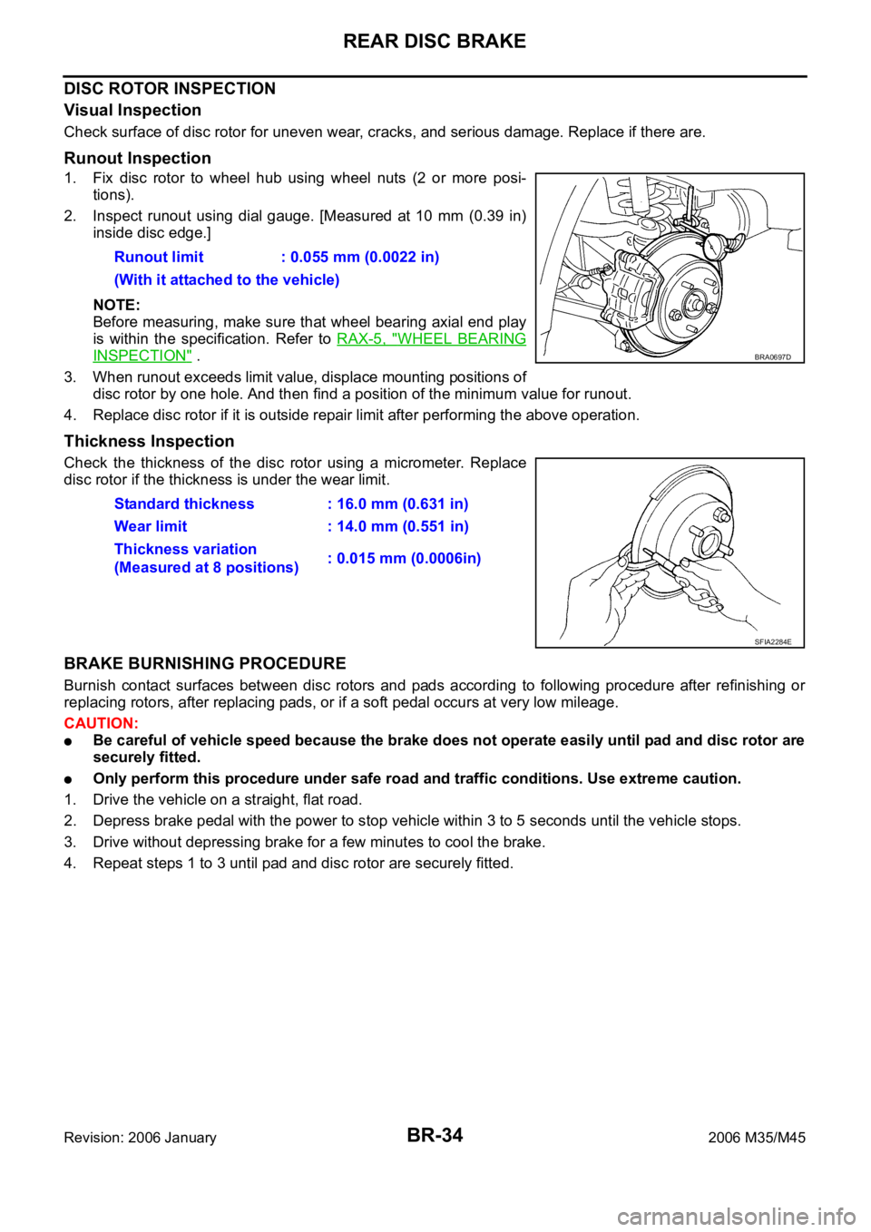
1. Fix disc rotor to wheel hub using wheel nuts (2 or more posi-
tions).
2. Inspect runout using dial gauge. [Measured at 10 mm (0.39 in)
inside disc edge.]
NOTE:
Before measuring, make sure that wheel bearing axial end play
is within the specification. Refer to RAX-5, "
WHEEL BEARING
INSPECTION" .
3. When runout exceeds limit value, displace mounting positions of
disc rotor by one hole. And then find a position of the minimum value for runout.
4. Replace disc rotor if it is outside repair limit after performing the above operation.
Thickness Inspection
Check the thickness of the disc rotor using a micrometer. Replace
disc rotor if the thickness is under the wear limit.
BRAKE BURNISHING PROCEDURE
Burnish contact surfaces between disc rotors and pads according to following procedure after refinishing or
replacing rotors, after replacing pads, or if a soft pedal occurs at very low mileage.
CAUTION:
Be careful of vehicle speed because the brake does not operate easily until pad and disc rotor are
securely fitted.
Only perform this procedure under safe road and traffic conditions. Use extreme caution.
1. Drive the vehicle on a straight, flat road.
2. Depress brake pedal with the power to stop vehicle within 3 to 5 seconds until the vehicle stops.
3. Drive without depressing brake for a few minutes to cool the brake.
4. Repeat steps 1 to 3 until pad and disc rotor are securely fitted. Runout limit : 0.055 mm (0.0022 in)
(With it attached to the vehicle)
BRA0697D
Standard thickness : 16.0 mm (0.631 in)
Wear limit : 14.0 mm (0.551 in)
Thickness variation
(Measured at 8 positions): 0.015 mm (0.0006in)
SFIA2284E
Page 3149 of 5621
![INFINITI M35 2006 Factory Service Manual EM-86
[VQ35DE]
CAMSHAFT
Revision: 2006 January2006 M35/M45
7. Remove timing chain tensioner (secondary) from cylinder head.
Remove timing chain tensioner (secondary) with its stopper
pin attach INFINITI M35 2006 Factory Service Manual EM-86
[VQ35DE]
CAMSHAFT
Revision: 2006 January2006 M35/M45
7. Remove timing chain tensioner (secondary) from cylinder head.
Remove timing chain tensioner (secondary) with its stopper
pin attach](/manual-img/42/57023/w960_57023-3148.png)
EM-86
[VQ35DE]
CAMSHAFT
Revision: 2006 January2006 M35/M45
7. Remove timing chain tensioner (secondary) from cylinder head.
Remove timing chain tensioner (secondary) with its stopper
pin attached.
NOTE:
Stopper pin should be attached when timing chain (secondary)
is removed.
INSPECTION AFTER REMOVAL
Camshaft Runout
1. Put V-block on precise flat table, and support No. 2 and 4 jour-
nals of camshaft.
CAUTION:
Do not support No. 1 journal (on the side of camshaft
sprocket) because it has a different diameter from the other
three locations.
2. Set a dial indicator vertically to No. 3 journal.
3. Turn camshaft to one direction with hands, and measure the
camshaft runout on a dial indicator. (Total indicator reading)
4. If it exceeds the limit, replace camshaft.
Camshaft Cam Height
1. Measure the camshaft cam height with a micrometer.
2. If wear exceeds the limit, replace camshaft.
Camshaft Journal Oil Clearance
CAMSHAFT JOURNAL DIAMETER
Measure the outer diameter of camshaft journal with a microme-
ter.
CAMSHAFT BRACKET INNER DIAMETER
Tighten camshaft bracket bolt with the specified torque. Refer to EM-89, "INSTALLATION" for the tighten-
ing procedure.
PBIC2111E
Standard : Less than 0.02 mm (0.001 in)
Limit : 0.05 mm (0.002 in)PBIC0929E
Standard cam height (intake and exhaust)
: 44.865 - 45.055 mm (1.7663 - 1.7738 in)
Cam wear limit
: 0.2 mm (0.0078 in)
EMQ0072D
Standard:
No. 1 : 25.935 - 25.955 mm (1.0211 - 1.0218 in)
No. 2, 3, 4 : 23.445 - 23.465 mm (0.9230 - 0.9238 in)
PBIC0040E
Page 3150 of 5621
![INFINITI M35 2006 Factory Service Manual CAMSHAFT
EM-87
[VQ35DE]
C
D
E
F
G
H
I
J
K
L
MA
EM
Revision: 2006 January2006 M35/M45
Measure inner diameter “A” of camshaft bracket with a bore
gauge.
CAMSHAFT JOURNAL OIL CLEARANCE
(Oil INFINITI M35 2006 Factory Service Manual CAMSHAFT
EM-87
[VQ35DE]
C
D
E
F
G
H
I
J
K
L
MA
EM
Revision: 2006 January2006 M35/M45
Measure inner diameter “A” of camshaft bracket with a bore
gauge.
CAMSHAFT JOURNAL OIL CLEARANCE
(Oil](/manual-img/42/57023/w960_57023-3149.png)
CAMSHAFT
EM-87
[VQ35DE]
C
D
E
F
G
H
I
J
K
L
MA
EM
Revision: 2006 January2006 M35/M45
Measure inner diameter “A” of camshaft bracket with a bore
gauge.
CAMSHAFT JOURNAL OIL CLEARANCE
(Oil clearance) = (Camshaft bracket inner diameter) – (Camshaft journal diameter).
If the calculated value exceeds the limit, replace either or both camshaft and cylinder head.
NOTE:
Camshaft brackets cannot be replaced as single parts, because there are machined together with cylinder
head. Replace whole cylinder head assembly.
Camshaft End Play
Install a dial indicator in thrust direction on front end of camshaft.
Measure the end play of a dial indicator when camshaft is
moved forward/backward (in direction to axis).
Measure the following parts if out of the limit.
–Dimension “A” for camshaft No. 1 journal
–Dimension “B” for cylinder head No. 1 journal bearing
Refer to the standards above, and then replace camshaft and/or
cylinder head.
Camshaft Sprocket Runout
1. Put V-block on precise flat table, and support No. 2 and 4 journals of camshaft.
CAUTION:
Do not support No. 1 journal (on the side of camshaft sprocket) because it has a different diameter
from the other three locations.Standard:
No. 1 : 26.000 - 26.021 mm (1.0236 - 1.0244 in)
No. 2, 3, 4 : 23.500 - 23.521 mm (0.9252 - 0.9260 in)
PBIC1645E
Standard:
No. 1 : 0.045 - 0.086 mm (0.0018 - 0.0034 in)
No. 2, 3, 4 : 0.035 - 0.076 mm (0.0014 - 0.0030 in)
Limit : 0.15 mm (0.0059 in)
Standard : 0.115 - 0.188 mm (0.0045 - 0.0074 in)
Limit : 0.24 mm (0.0094 in)
SEM864E
Standard : 27.500 - 27.548 mm (1.0827 - 1.0846 in)
Standard : 27.360 - 27.385 mm (1.0772 - 1.0781 in)
KBIA2404J