2006 INFINITI M35 run flat
[x] Cancel search: run flatPage 3209 of 5621
![INFINITI M35 2006 Factory Service Manual EM-146
[VQ35DE]
CYLINDER BLOCK
Revision: 2006 January2006 M35/M45
CRANKSHAFT PIN JOURNAL DIAMETER
Measure the outer diameter of crankshaft pin journal with a
micrometer.
If out of the sta INFINITI M35 2006 Factory Service Manual EM-146
[VQ35DE]
CYLINDER BLOCK
Revision: 2006 January2006 M35/M45
CRANKSHAFT PIN JOURNAL DIAMETER
Measure the outer diameter of crankshaft pin journal with a
micrometer.
If out of the sta](/manual-img/42/57023/w960_57023-3208.png)
EM-146
[VQ35DE]
CYLINDER BLOCK
Revision: 2006 January2006 M35/M45
CRANKSHAFT PIN JOURNAL DIAMETER
Measure the outer diameter of crankshaft pin journal with a
micrometer.
If out of the standard, measure the connecting rod bearing oil
clearance. Then use undersize bearing. Refer to EM-146,
"CONNECTING ROD BEARING OIL CLEARANCE" .
CRANKSHAFT OUT-OF-ROUND AND TAPER
Measure the dimensions at four different points as shown in the
figure on each main journal and pin journal with a micrometer.
Out-of-round is indicated by the difference in the dimensions
between “X” and “Y” at “A” and “B”.
Taper is indicated by the difference in the dimensions between
“A” and “B” at “X” and “Y”.
If the measured value exceeds the limit, correct or replace crankshaft.
If corrected, measure the bearing oil clearance of the corrected main journal and/or pin journal. Then
select the main bearing and/or connecting rod bearing. Refer to EM-147, "
MAIN BEARING OIL CLEAR-
ANCE" and/or EM-146, "CONNECTING ROD BEARING OIL CLEARANCE" .
CRANKSHAFT RUNOUT
Place V-block on precise flat table, and support the journals on
the both end of crankshaft.
Place a dial indicator straight up on the No. 3 journal.
While rotating crankshaft, read the movement of the pointer on a
dial indicator. (Total indicator reading)
If it exceeds the limit, replace crankshaft.
CONNECTING ROD BEARING OIL CLEARANCE
Method by Calculation
Install connecting rod bearings to connecting rod and connect-
ing rod cap, and tighten connecting rod bolts to the specified
torque. Refer to EM-128, "
ASSEMBLY" for the tightening proce-
dure.
Measure the inner diameter of connecting rod bearing with an
inside micrometer.
(Oil clearance) = (Connecting rod bearing inner diameter) – (Crank-
shaft pin journal diameter)Standard : 51.956 - 51.974 mm (2.0455 - 2.0462 in) dia.
PBIC0127E
Limit:
Out-of-round (Difference between “X” and “Y”)
: 0.002 mm (0.0001 in)
Taper (Difference between “A” and “B”)
: 0.002 mm (0.0001 in)
SBIA0535E
Standard : Less than 0.05 mm (0.002 in)
Limit : 0.10 mm (0.004 in)
SEM346D
PBIC1642E
Page 3279 of 5621
![INFINITI M35 2006 Factory Service Manual EM-216
[VK45DE]
CAMSHAFT
Revision: 2006 January2006 M35/M45
3. With hexagonal part of camshaft locked with wrench, loosen
bolts securing camshaft sprocket to remove camshaft sprocket.
CAUTION INFINITI M35 2006 Factory Service Manual EM-216
[VK45DE]
CAMSHAFT
Revision: 2006 January2006 M35/M45
3. With hexagonal part of camshaft locked with wrench, loosen
bolts securing camshaft sprocket to remove camshaft sprocket.
CAUTION](/manual-img/42/57023/w960_57023-3278.png)
EM-216
[VK45DE]
CAMSHAFT
Revision: 2006 January2006 M35/M45
3. With hexagonal part of camshaft locked with wrench, loosen
bolts securing camshaft sprocket to remove camshaft sprocket.
CAUTION:
Do not loosen mounting bolts with securing anything
other than the camshaft hexagonal portion or with ten-
sioning the timing chain.
After removing timing chain, do not turn crankshaft and
camshaft separately, or valves will strike the piston head.
4. Remove intake and exhaust camshaft brackets.
Mark camshafts, camshaft brackets and bolts so placed in the same position and direction for installa-
tion.
Equally loosen camshaft brackets and bolts in several steps in
reverse order as shown in the figure.
Lightly tapping with plastic hammer, remove camshaft bracket
(No. 1) and camshaft bracket (No. 6).
NOTE:
The bottom surface of each bracket will be stuck to cylinder
head because of liquid gasket.
5. Remove camshaft.
6. Remove adjusting shim and valve lifter if necessary.
Identify installation positions, and store them without mixing them up.
INSPECTION AFTER REMOVAL
Camshaft Runout
1. Put V-block on precise flat table, and support No. 2 and 5 journal
of camshaft.
CAUTION:
Do not support journal No. 1 (on the side of camshaft
sprocket) because it has a different diameter from the other
four locations.
2. Set dial indicator vertically to No. 3 journal.
3. Turn camshaft to one direction with hands, and measure the
camshaft runout on dial indicator (total indicator reading).
PBIC0030E
PBIC0031E
Standard:
0.02 mm (0.001 in)PBIC2499E
Page 3281 of 5621
![INFINITI M35 2006 Factory Service Manual EM-218
[VK45DE]
CAMSHAFT
Revision: 2006 January2006 M35/M45
Camshaft End Play
Install dial indicator in thrust direction on front end of camshaft.
Measure the end play of dial indicator when INFINITI M35 2006 Factory Service Manual EM-218
[VK45DE]
CAMSHAFT
Revision: 2006 January2006 M35/M45
Camshaft End Play
Install dial indicator in thrust direction on front end of camshaft.
Measure the end play of dial indicator when](/manual-img/42/57023/w960_57023-3280.png)
EM-218
[VK45DE]
CAMSHAFT
Revision: 2006 January2006 M35/M45
Camshaft End Play
Install dial indicator in thrust direction on front end of camshaft.
Measure the end play of dial indicator when camshaft is moved
forward/backward (in direction to axis).
Measure the following parts if out of the standard.
–Dimension “A” for camshaft No. 1 journal
–Dimension “B” for cylinder head No. 1 journal bearing
Refer to the standards above, and then replace camshaft and/or
cylinder head.
Camshaft Sprocket Runout
1. Put V-block on precise flat table, and support No. 2 and 5 journal of camshaft.
CAUTION:
Do not support journal No. 1 (on the side of camshaft sprocket) because it has a different diameter
from the other four locations.
2. Measure the camshaft sprocket runout with dial indicator. (Total
indicator reading)
If it exceeds the limit, replace camshaft sprocket.
Valve Lifter and Adjusting Shim
Check if surface of valve lifter and adjusting shim has any wear or
cracks.
If anything above is found, replace valve lifter.
When replacing adjusting shim, refer to EM-225, "ADJUST-
MENT" . Standard:
0.115 - 0.188 mm (0.0045 - 0.0074 in)
PBIC2446E
Standard : 30.500 - 30.548 mm (1.2008 - 1.2027 in)
Standard : 30.360 - 30.385 mm (1.1953 - 1.1963 in)
KBIA2426J
Limit : 0.15 mm (0.0059 in)
PBIC0930E
PBIC0231E
Page 3335 of 5621
![INFINITI M35 2006 Factory Service Manual EM-272
[VK45DE]
CYLINDER BLOCK
Revision: 2006 January2006 M35/M45
If out of the standard, measure the main bearing oil clearance. Then use undersize bearing. Refer to EM-
274, "MAIN BEARING OIL CL INFINITI M35 2006 Factory Service Manual EM-272
[VK45DE]
CYLINDER BLOCK
Revision: 2006 January2006 M35/M45
If out of the standard, measure the main bearing oil clearance. Then use undersize bearing. Refer to EM-
274, "MAIN BEARING OIL CL](/manual-img/42/57023/w960_57023-3334.png)
EM-272
[VK45DE]
CYLINDER BLOCK
Revision: 2006 January2006 M35/M45
If out of the standard, measure the main bearing oil clearance. Then use undersize bearing. Refer to EM-
274, "MAIN BEARING OIL CLEARANCE" .
CRANKSHAFT PIN JOURNAL DIAMETER
Measure the outer diameter of crankshaft pin journal with
micrometer.
If out of the standard, measure the connecting rod bearing oil
clearance. Then use undersize bearing. Refer to EM-273,
"CONNECTING ROD BEARING OIL CLEARANCE" .
CRANKSHAFT OUT-OF-ROUND AND TAPER
Measure the dimensions at four different points as shown in the
figure on each main journal and pin journal with micrometer.
Out-of-round is indicated by the difference in the dimensions
between “X” and “Y” at “A” and “B”.
Taper is indicated by the difference in the dimensions between
“A” and “B” at “X” and “Y”.
If the measured value exceeds the limit, correct or replace crankshaft.
If corrected, measure the bearing oil clearance of the corrected main journal and/or pin journal. Then
select the main bearing and/or connecting rod bearing. Refer to EM-274, "
MAIN BEARING OIL CLEAR-
ANCE" and/or EM-273, "CONNECTING ROD BEARING OIL CLEARANCE" .
CRANKSHAFT RUNOUT
Place V-block on precise flat table, and support the journals on
the both end of crankshaft.
Place dial indicator straight up on the No. 3 journal.
While rotating crankshaft, read the movement of the pointer on
dial indicator (total indicator reading).
If it exceeds the limit, replace crankshaft.Standard : 63.940 - 63.964 mm (2.5173 - 2.5183 in) dia.
Standard : 51.956 - 51.974 mm (2.0455 - 2.0462 in) dia.
PBIC0127E
Limit:
Out-of-round (Difference between “X” and “Y”)
: 0.015 mm (0.0006 in)
Taper (Difference between “A” and “B”)
: 0.010 mm (0.0004 in)
PBIC1685E
Standard : Less than 0.05 mm (0.002 in)
Limit : 0.10 mm (0.004 in)
PBIC2378E
Page 3397 of 5621

FFD-20
FRONT FINAL DRIVE ASSEMBLY
Revision: 2006 January2006 M35/M45
c. If the runout value is still outside of the limit after the check and repair, replace companion flange.
DISASSEMBLY
Side Shaft Assembly
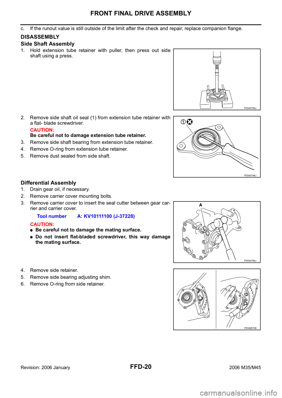
1. Hold extension tube retainer with puller, then press out side
shaft using a press.
2. Remove side shaft oil seal (1) from extension tube retainer with
a flat- blade screwdriver.
CAUTION:
Be careful not to damage extension tube retainer.
3. Remove side shaft bearing from extension tube retainer.
4. Remove O-ring from extension tube retainer.
5. Remove dust sealed from side shaft.
Differential Assembly
1. Drain gear oil, if necessary.
2. Remove carrier cover mounting bolts.
3. Remove carrier cover to insert the seal cutter between gear car-
rier and carrier cover.
CAUTION:
Be careful not to damage the mating surface.
Do not insert flat-bladed screwdriver, this way damage
the mating surface.
4. Remove side retainer.
5. Remove side bearing adjusting shim.
6. Remove O-ring from side retainer.
PDIA0793J
PDIA0794J
Tool number A: KV10111100 (J-37228)
PDIA0795J
PDIA0670E
Page 5009 of 5621

RAX-10
REAR DRIVE SHAFT
Revision: 2006 January2006 M35/M45
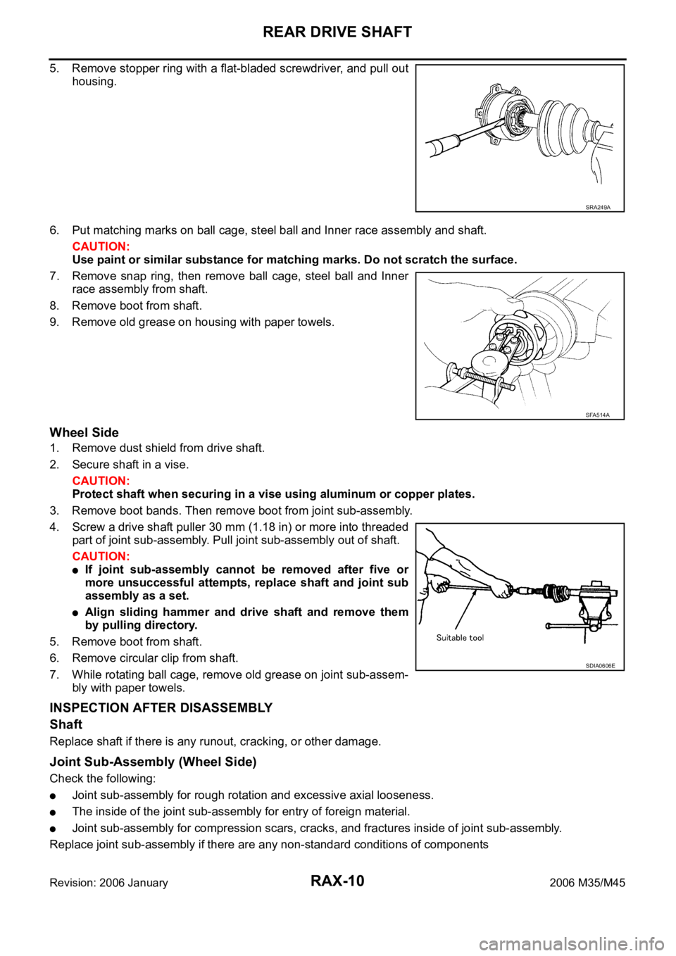
5. Remove stopper ring with a flat-bladed screwdriver, and pull out
housing.
6. Put matching marks on ball cage, steel ball and Inner race assembly and shaft.
CAUTION:
Use paint or similar substance for matching marks. Do not scratch the surface.
7. Remove snap ring, then remove ball cage, steel ball and Inner
race assembly from shaft.
8. Remove boot from shaft.
9. Remove old grease on housing with paper towels.
Wheel Side
1. Remove dust shield from drive shaft.
2. Secure shaft in a vise.
CAUTION:
Protect shaft when securing in a vise using aluminum or copper plates.
3. Remove boot bands. Then remove boot from joint sub-assembly.
4. Screw a drive shaft puller 30 mm (1.18 in) or more into threaded
part of joint sub-assembly. Pull joint sub-assembly out of shaft.
CAUTION:
If joint sub-assembly cannot be removed after five or
more unsuccessful attempts, replace shaft and joint sub
assembly as a set.
Align sliding hammer and drive shaft and remove them
by pulling directory.
5. Remove boot from shaft.
6. Remove circular clip from shaft.
7. While rotating ball cage, remove old grease on joint sub-assem-
bly with paper towels.
INSPECTION AFTER DISASSEMBLY
Shaft
Replace shaft if there is any runout, cracking, or other damage.
Joint Sub-Assembly (Wheel Side)
Check the following:
Joint sub-assembly for rough rotation and excessive axial looseness.
The inside of the joint sub-assembly for entry of foreign material.
Joint sub-assembly for compression scars, cracks, and fractures inside of joint sub-assembly.
Replace joint sub-assembly if there are any non-standard conditions of components
SRA249A
SFA514A
SDIA0606E
Page 5065 of 5621

RFD-22
REAR FINAL DRIVE ASSEMBLY
Revision: 2006 January2006 M35/M45
Companion Flange Runout
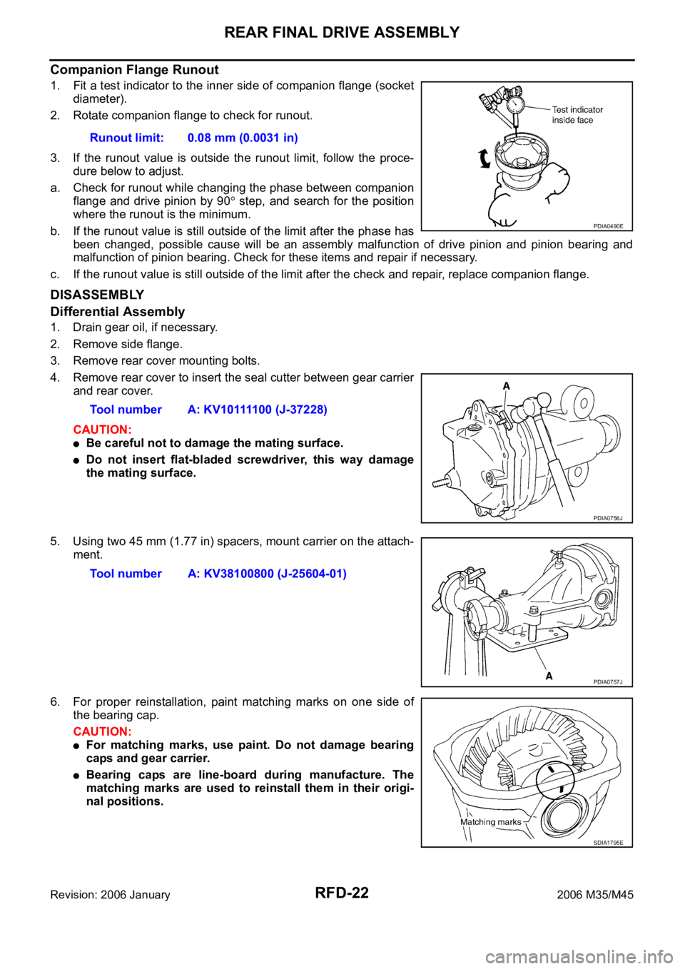
1. Fit a test indicator to the inner side of companion flange (socket
diameter).
2. Rotate companion flange to check for runout.
3. If the runout value is outside the runout limit, follow the proce-
dure below to adjust.
a. Check for runout while changing the phase between companion
flange and drive pinion by 90
step, and search for the position
where the runout is the minimum.
b. If the runout value is still outside of the limit after the phase has
been changed, possible cause will be an assembly malfunction of drive pinion and pinion bearing and
malfunction of pinion bearing. Check for these items and repair if necessary.
c. If the runout value is still outside of the limit after the check and repair, replace companion flange.
DISASSEMBLY
Differential Assembly
1. Drain gear oil, if necessary.
2. Remove side flange.
3. Remove rear cover mounting bolts.
4. Remove rear cover to insert the seal cutter between gear carrier
and rear cover.
CAUTION:
Be careful not to damage the mating surface.
Do not insert flat-bladed screwdriver, this way damage
the mating surface.
5. Using two 45 mm (1.77 in) spacers, mount carrier on the attach-
ment.
6. For proper reinstallation, paint matching marks on one side of
the bearing cap.
CAUTION:
For matching marks, use paint. Do not damage bearing
caps and gear carrier.
Bearing caps are line-board during manufacture. The
matching marks are used to reinstall them in their origi-
nal positions.Runout limit: 0.08 mm (0.0031 in)
PDIA0490E
Tool number A: KV10111100 (J-37228)
PDIA0756J
Tool number A: KV38100800 (J-25604-01)
PDIA0757J
SDIA1795E
Page 5531 of 5621

WT-6
ROAD WHEEL
Revision: 2006 January2006 M35/M45
ROAD WHEELPFP:40300
InspectionNES000JO
ALUMINUM WHEEL
1. Check tires for wear and improper inflation.
2. Check wheels for deformation, cracks and other damage. If deformed, remove wheel and check wheel
runout.
a. Remove tire from aluminum wheel and mount on a tire balance machine.
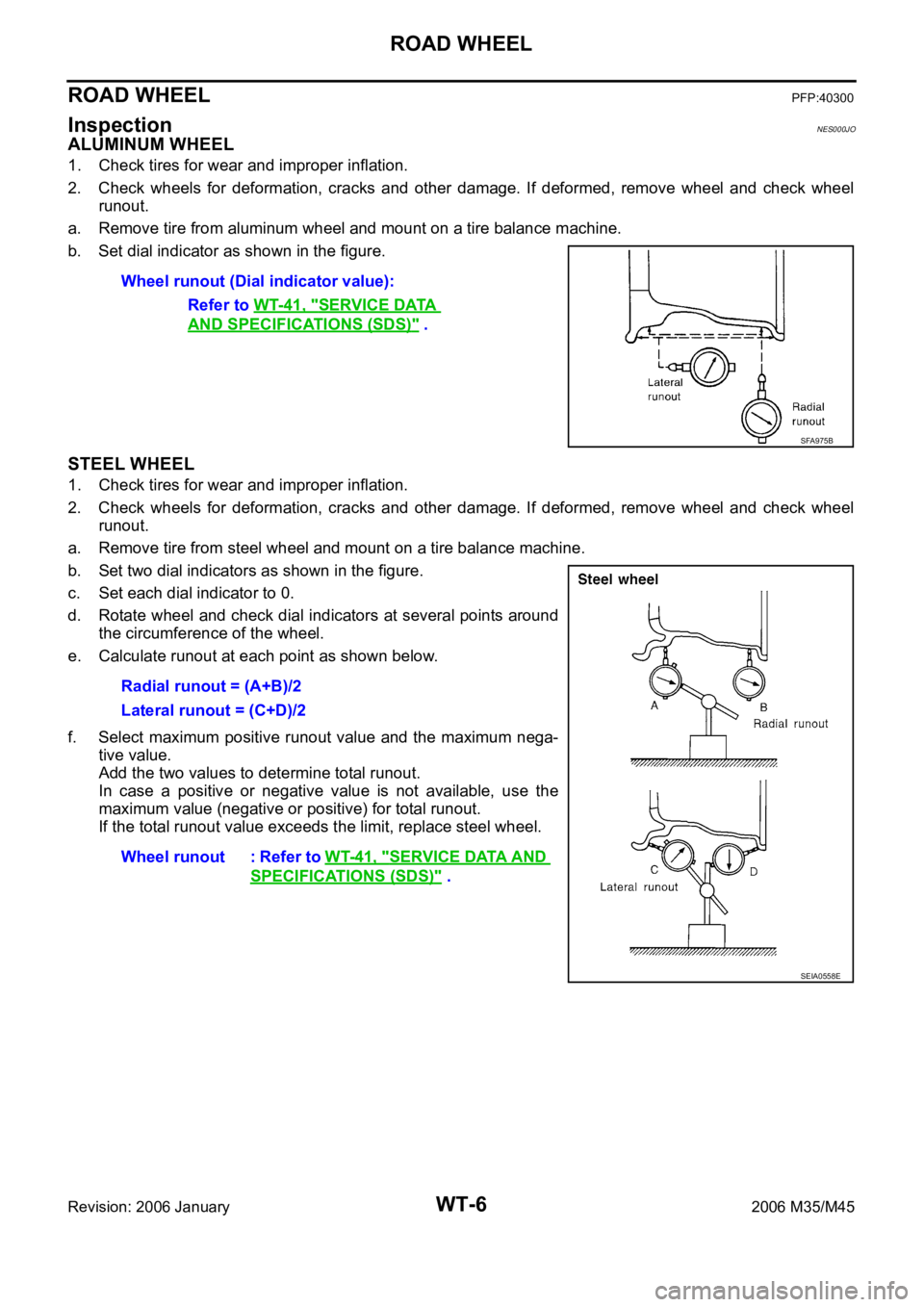
b. Set dial indicator as shown in the figure.
STEEL WHEEL
1. Check tires for wear and improper inflation.
2. Check wheels for deformation, cracks and other damage. If deformed, remove wheel and check wheel
runout.
a. Remove tire from steel wheel and mount on a tire balance machine.
b. Set two dial indicators as shown in the figure.
c. Set each dial indicator to 0.
d. Rotate wheel and check dial indicators at several points around
the circumference of the wheel.
e. Calculate runout at each point as shown below.
f. Select maximum positive runout value and the maximum nega-
tive value.
Add the two values to determine total runout.
In case a positive or negative value is not available, use the
maximum value (negative or positive) for total runout.
If the total runout value exceeds the limit, replace steel wheel. Wheel runout (Dial indicator value):
Refer to WT-41, "
SERVICE DATA
AND SPECIFICATIONS (SDS)" .
SFA975B
Radial runout = (A+B)/2
Lateral runout = (C+D)/2
Wheel runout : Refer to WT-41, "
SERVICE DATA AND
SPECIFICATIONS (SDS)" .
SEIA0558E